1
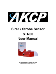
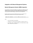
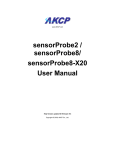
Airflow Sensor User
Manual
Percentage & On / Off Type
Firmware versions SP456 / SEC404j
Copyright © 2012, AKCess Pro Co., Ltd..
Airflow Sensor User Manual
Introduction
There are two versions of AKCP Airflow sensors. A percentage type and an On and Off type. The
percentage type was replaced by the On and Off type around August of 2011.
The percentage type, AKCP’s first version of its Airflow sensor was a sensor that could measure
the amount of airflow in a percentage and will be covered first in this manual. The second type,
the On / Off type will be covered after.
Percentage Reading Type Airflow Sensor
The way the percentage type air flow sensor works is there are two thermistors, one internal and
one external. A thermistor changes resistance based on air temperature. The internal thermistor
is the reference point and the external thermistor changes when the airflow is blown across the
top of the sensor, the difference is this raw output reading. Then the raw output reading is
calculated into the percentage of airflow.
The calculations are as follows;
rawAnalog 550 = 1.375 Volt = 100%
rawAnalog 150 = 0.375 Volt = 0%
The sensor will be much more accurate if it is positioned so the air flows across the top of the
sensor and this is not a precision sensor. It is basically designed to sense the presence and
non-presence of airflow.
The airflow sensor is really designed to sense the presence of air, not to measure the amount of
airflow. The best application is to place it near the air source but if you want a reading of less than
100% then you need to place it further away but again it is not designed to be an anemometer. It
is best used to send an alert in the case of a fan, or in your case, AC failure.
If you need a more precision sensor then these are much more expensive but can be integrated
into the AKCP base units. Please contact support for more information.
The Airflow Sensor is a device that registers airflow in areas where consistent flow is needed; for
example, in cabinets and racks where the consistent operation of a fan is critical to the
operational safety of electronic equipment.
The Airflow sensor is placed in the air stream, where the user can monitor the status and the
amount of flowing air. In addition to an on/off indication, it also graphs the analog values over a
period of time. Although this is not a precision airspeed measurement device, it can be used, for
example, to indicate if a fan slows down the user will be given an indication of the change over
time. This may happen if the fan is close to failure or the air filter is clogged.
The recognized OID for the air flow sensor on RJ45#1 is .1.3.6.1.4.1.3854.1.2.2.1.17.1.3.0
Features:
o
On/Off alarm signal of airflow
o
Airflow data graphically displayed over time
o
Accurate, cost effective flow sensing
o
2 LEDs indicate the status of Airflow and that the sensor is securely plugged into the
unit
o
Electronics are mounted in a small plastic case
-2-
Airflow Sensor User Manual
o
Power source: powered by the unit. No additional power needed.
o
The unit auto detects the presence of the airflow sensor .
o
Full Autosense including disconnect alarm
Specifications:
o
Data graphically displayed via a web page
o
Data collection possible via any SNMP based network management system
o
Measurement rate: one reading each second, data logging once per minute
o
Communication cable: RJ-45 jack to the unit
o
Sensor type: Thermistor
o
Trap information: Status, Sensor number, Sensor description, Airflow (%) (ONLY on
the older type airflow sensor)
o
Maximum CAT5/6 Cable Extension Run Length: 60 meters or 200 feet.
Configuring the airflow sensor
a) Plug the sensor into one of the RJ45 ports on the rear panel of the unit.
b) Now point your browser to the IP address of the unit (default, 192.168.0.100). Next you need
to login as the administrator using your administrator password (default is “public”). You will then
be taken to the summary page.
c) From the summary page you need to select the sensors tab. The layout of the next page will
vary depending on your unit so please refer to your units manual.
Now we will cover the settings that are specific to your sensor.
Current Reading: The percentage of airflow is displayed in this field. This is a read-only field. It is
an integer SNMP OID field. This value can be polled via SNMP and the data can be used to
graph the air-flow. The values range is from 0 to 100 %.
Status: If the sensor is offline, the status shows “No Status”. If the sensor is online, the status
will be formed by comparing the readings to the low thresholds. If at any time communications
with the Airflow Sensor are lost, the status of the Airflow Sensor is changed to “sensorError”.
Can I extend the airflow sensor, if yes, how do I do that and how far can I extend it?
Yes, you can extend the airflow sensor using standard CAT5 LAN cable. The total run length of
this sensor is 30 meters or roughly 98 feet.
On / Off Type Airflow Sensor
AKCP is only shipping the On / Off type of Airflow sensor.
-3-
Airflow Sensor User Manual
Configuring the airflow sensor on your sensorProbe unit
a) Plug the sensor into one of the RJ45 ports on the rear panel of the unit.
b) Now point your browser to the IP address of the unit (default, 192.168.0.100). Next you need
to login as the administrator using your administrator password (default is “public”). You will then
be taken to the summary page.
c) From the summary page you need to select the sensors tab. The layout of the next page will
vary depending on your unit so please refer to your units manual.
Now we will cover the settings that are specific to your sensor.
sensorProbe Base Units
After connecting the sensor it will be auto sensed as the Airflow Sensor. After clicking on
the Sensors tab you would then click on the sensor settings link as shown in the screen
shot above.
In the settings tab you first make sure the sensor is online, and then you can re-name
your Airflow sensor, adjust the rearm and sensitivity settings and change the Normal
State.
-4-
Airflow Sensor User Manual
You can change the Normal state to be in the normal state when the airflow is present or
not present. This is quite convenient in the event you required to be alerted if airflow was
moving in a direction that was not desired for example an air sealed clean lab where air
flow should only be flowing out of the room and not in.
After clicking on Calibrate tab, you are able to calibrate the airflow sensor. The airflow
sensor should be calibrated only if the sensor does not seem to be detecting airflow
properly.
To calibrate the sensor follow the instructions on the screen and click on the calibrate b
utton as shown in the screen shot above.
After clicking on the Calibrate button, a reminder will be displayed as shown above, then
you would click the OK button to begin the calibration of the airflow sensor.
For the Relay Control and Siren Control please see the Dry Contact, Sensor Controlled
Relay or the Siren / Strobe user manuals for information on these options.
-5-
Airflow Sensor User Manual
Clicking on the Status Filters tab we can see now that you can enable or disable the email and traps for this,
enable or disable the email or trap when the status returns to a Normal State and also set the Continuous Time
settings to elimate false warnings, set the Minimum time between each Email or Trap and also set the Day and
Time filter as shown in the screen shot above.
securityProbe Base Units
After connecting the sensor to the RJ-45 sensor port and logging into the unit as the
Admin and navigating to the Sensors page the airflow sensor will be auto sensed and
displayed as shown in the screen shot above.
-6-
Airflow Sensor User Manual
After clicking on the Airflow sensor the Normal Settings will be displayed where you are
able to then rename the sensor, rename the Status and change the Normal State to the
Presence or Absence of airflow.
The sensitivity can be set to a specific number in the event the airflow is a lot or very low.
To calibrate the Airflow Sensor, click in the Calibrate button as shown above.
After clicking on Calibrate button, you are able to calibrate the airflow sensor. The airflow
sensor should be calibrated only if the sensor does not seem to be detecting airflow
properly.
-7-
Airflow Sensor User Manual
To calibrate the sensor follow the instructions on the screen and click on the calibrate
button as shown in the screen shot above.
After clicking on the Calibrate button, a reminder will be displayed as shown above, then
you would click the OK button to begin the calibration of the airflow sensor.
-8-
Airflow Sensor User Manual
This concludes the Time Tracking feature user manual.
Please contact [email protected] if you have any further technical questions or problems setting up your
modem or your alerts.
Thanks for Choosing AKCess Pro!
-9-