1
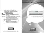
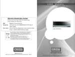
Warranty Registration System
Help us to serve you better by registering
your product for Warranty
Web
Register at www.onida.com
Telephone
Call Centre No. 0XX-39889000(0XX-STD Code of
State Capital)
Post / Visit
Post the Warranty Registration Card & Service Centre
Copy or Visit the Nearest Service Centre.
Model: INV18ELE7
As per Government of India’s E-Waste (Management and Handling)
Rules, 2011(effective from May 1st, 2012) the product purchased by you
is to be considered as E-Waste and cannot be disposed off with your
general household waste. It should be disposed of through the company’s
collection center so as to prevent any damage to environment
Collection Center address
Mirc Electronics Ltd.Village Kudus,Bhiwandi Wada road,
Taluka Wada., Dist. Thane - 421312,Tel no. 952525 220375/377
Visit at : www.onida.com for details about collection Centers.
We request you to make a note of the above details and support us
in our endeavour to ensure an environmental friendly nation.
AIR CONDITIONERS
The unit displayed is for representational purposes only. Actual unit may vary.
Dear customer
Congratulation on buying ONIDA Air Conditioner.
Your Air Conditioner comes with ONIDA Guarantee of Quality
as detailed in the manual.
ONIDA takes great pride in providing its customers with stateof-the-art products that adheres to international quality
standards.
ONIDA is committed to following quality policy laid by our
chairman and managing director Mr. G. L. Mirchandani.
“We are committed to quality and strive for continuous
improvement through innovation and human development to
give customer better value for money always”
ONIDA stands committed to provide the ultimate customer
satisfaction, as nothing brings us greater joy than having
satisfied customers of ONIDA.
At ONIDA, feedback and suggestions based on your product
usage experience is greatly appreciated.
Please contact to us at [email protected]
G. Sundar
Chief Executive Officer
IMPORTANT :
Please read this owner’s manual carefully and thoroughly
before installing and operating your room air conditioners.
Please retain this owner’s manual for future reference after
reading it thoroughly.
CONTENTS
Salient Features
1
Inside Overview
2
Indoor Unit Display
3
Remote Overview
4
Operations
8
Notices for installation
12
General Instructions for Installation
13
Installation Sketch
16
Installation
17
Take care of your Air Conditioner
20
Precautions to be taken
23
Trouble Shooting Chart
24
Installation and Satisfaction Report
25
Warranty Terms & Conditions
27
Preventive Maintenance Service Coupon
29
Warranty Card(Customer Copy)
Warranty Card(service Center Copy)
SALIENT FEATURES
Model Code :INV18ELE7
• Aesthetics:a) Unique Elegant Model with High EER
b) Sleek Indoor Unit
• Performance:a) Imported High BTU Tropicalised Compressor
b) Trapezoidal Inner Grooved Tube
c) Large L - Shaped Condenser Coil
d) High RPM Fan Motor with High Static
• Features:a) Clean Air
b) Multi-Step Air Swing for Customized Cooling
c) Surround Air
d) Turbo
• Safety & Reliability:a) Hydrophilic Fins
b) Full Function LCD Remote
c) Special Insulation on the Air Vent
d) 5-Stage Epoxy Polyester Painting
1
INSIDE OVERVIEW
n
INDOOR UNIT DISPLAY
Display on the indoor unit.
INDOOR UNIT
For the icon of LED windows, only relevant icons will light up with their displays on.
Return warm Air in
Front panel
Display
SET TEMP
SET TEMPERATURE( C)
Conditioned Air out
TURBO
HIGH
MED
LOW
AUTO
COOL
DRY
FAN
TEMP
MODE
ON/OFF
ENERGY
SAVER
SWING
FAN
TIMER ON/OFF
TURBO RESET LOCK
i-Cool
CLEAN
AIR
SELF
CLEAN
SLEEP/
DISPLAY
FOLLOW
ME
COOL
Remote controller
DRY
HEAT
n
OUTDOOR UNIT
POWER
Air in
ON/OFF
Connection
pipe and
connecting wire
RECEIVER
Exhaust Air
2
3
REMOTE OVERVIEW
REMOTE OVERVIEW
Replacement of Batteries
1) ON/OFF
Press it to start or stop operation.
1) Remove the battery cover plate from the
rear of the remote controller. (As shown in
the figure)
2) MODE
Press it to select operation mode(AUTO/COOL/DRY/FAN/HEAT)
3) ‘’ - ‘’
Press it to decrease temperature setting.
2) Take out the old batteries.
3) Insert two new AAA1.5V dry batteries,
and pay attention to the polarity .
4) ‘’ + ’’
Press it to increase temperature setting.
4) Reinstall the battery cover plate.
5) FAN
Press it to set fan speed .
Notes:
Ÿ When replacing the batteries, do not
use old or different batteries, otherwise,
it may cause malfunction.
Ÿ If the wireless remote controller will not
be used for a long time, please remove
batteries to prevent damage from
leaking batteries.
Ÿ The operation should be performed in
its receiving range.
Ÿ It should be kept 1m away from the TV
set or stereo sound sets.
Ÿ If the wireless remote controller does
not operate normally, please take
Ÿ the batteries out and reinsert them after
30 seconds. If it still can't operate
properly, replace the batteries.
6)
Press it to set up & down swing angle.
7) HEALTH SAVE ( page 7)
Press it to turn on or off health function.
8)
Press it to set left & right swing angle.
9) X-FAN
( page 7)
10) TEMP
( page 7)
11) TIMER
Press it to set timer ON/ timer OFF.
12) TURBO
( page 8)
13) SLEEP
( page 8)
14) LIGHT
Press it to turn on/off the light.
4
5
OPERATIONS
OPERATIONS
20) Up & down swing icon:
is displayed when pressing the up & down swing button. Press this button again to
clear the display.
21) Left & right swing icon:
is displayed when pressing the left & right swing button. Press this button again to
clear the display.
22)SET TIME display:
After pressing TIMER button, ON or OFF will blink. This area will show the set time.
23) DIGITAL display:
This area will show the set tempe-rature. In SAVE mode,"SE" will be displayed. During
defrosting opera-tion, “H1” will be displayed.
24) FAN SPEED display:
Press FAN button to select the desired fan speed setting(AUTO-Low-Med-High).Your
selection will be displayed in the LCD windows, except the AUTO fan speed.
15) MODE icon:
If MODE button is pressed, current operation mode icon (AUTO),
(DRY), (FAN) or (HEAT only for heat pump models) will show.
( COOL),
16) LOCK icon:
is displayed by pressing "+" and “-” buttons simultaneously. Press them again to clear
the display.
17) LIGHT icon:
is displayed by pressing the LIGHT button. Press LIGHT button again to clear the
display.
18) SLEEP icon :
is displayed by pressing the SLEEP button. Press this button again to clear the
display.
19) TEMP icon:
Pressing TEMP button, (set temperature), (indoor ambient temperature) (outdoor
ambient temperature) and blank is displayed circularly.
6
7
OPERATIONS
OPERATIONS
1) ON/OFF
Press this button to turn on the unit. Press this button again to turn off the unit.
2) MODE
Each time you press this button,a mode is selected in a sequence that goes from
AUTO, COOL, DRY, FAN , and HEAT *, as the following:
Ÿ If the unit is turned off during swing operation , the louver will stop at present
position.
7)HEALTH SAVE
Press HEALTH part of this button to turn on or off HEALTH function. Pressing SAVE
part of this button,
is displayed and the unit goes into SAVE operation mode.
Press SAVE part of the button again to cancel SAVE function. During SAVE
operation, the temperature and fan speed is not adjustable
*Note: Only for models with heating function.
After energization , AUTO mode is defaulted. In AUTO mode, the set temperature
will not be displayed on the LCD, and the unit will automatically select the suitable
operation mode in accordance with the room temperature to make indoor room
comfortable.
8)
Ÿ Press
3) “ ”
Press this button to decrease set temperature. Hold it down for above 2 seconds to
rapidly decrease set temperature. In AUTO mode, set temperature is not adjustable.
4)“ ”
Press this button to increase set temperature. Hold it down for above 2 seconds to
rapidly increase set temperature. In AUTO mode, set temperature is not adjustable.
5) FAN
This button is used for setting fan speed in the sequence that goes from AUTO
, to
then back to Auto.
Ÿ
Medium speed
If the unit is turned off during swing operation, the louver will stop at present
position.
9) X-FAN
Pressing X-FAN button in COOL or DRY mode,the icon "X-FAN" is displayed and the
indoor fan will continue operation for 10 minutes in order to dry the indoor unit even
though you have turned off the unit.
After energization, X-FAN OFF is defaulted. X-FAN is not available in AUTO, FAN
and HEAT mode.
Note: X-FAN is the alternative expression of BLOW for the purpose of under standing.
Auto
Low speed
button to start or stop left & right swing function.The remote controller
defaults to simple swing condition.
Ÿ Press + button and
button at the same time at unit OFF to switch between
simple swing and static swing;
blinks for 2 seconds.
Ÿ In static swing condition, pressing
button, the swing angle of left & right
louver changes as below:
High speed
6)
Ÿ Press
button to start or stop up & down swing function. The remote controller
defaults to simple swing condition.
Ÿ Press + button and
button at the same time at unit OFF to switch between
simple swing and static swing blinks for 2 seconds.
Ÿ In static swing condition, pressing
button, the swing angle of up & down
louver changes as.
10) TEMP
Press this button, could select displaying the indoor setting temperature or indoor
ambient temperature.When the indoor unit firstly power on it will display the setting
temperature, if the temperature's displaying status is changed from other status
8
9
OPERATIONS
OPERATIONS
to" ",displays the ambient temperature, 5s later or within 5s, it receives other remote
control signal that will return to display the setting temperature. if the users haven't
set up the temperature displaying status, that will display the setting temperature.
Displayer indicator light control of indoor unit
Special selection button: for those users who do not want light at night.
Ÿ
11) TIMER
Press TIMER button at unit ON to set TIMER OFF; HOUR OFF blinks. Press TIMER
button at unit OFF to set TIMER ON; HOUR ON blinks. In this case, pressing + or button changes time setting. Holding down either button rapidly changes time
setting (time setting range 0.5-24hours). Press TIMER button again to confirm
setting; HOUR ON/OFF stops blinking. If there is not any operation of button within 5
seconds during HOUR ON/OFF blinking, TIMER setting will be cancelled.
12) TURBO
Press this button to activate / deactivate the Turbo function which enables the unit to
reach the preset temperature in shortest time. In COOL mode, the unit will blow
strong cooling air at super high fan speed. In HEAT mode, the unit will blow strong
heating air at super high fan speed. (This function is not applicable for some
models).
13) SLEEP
Press this button to go into the SLEEP operation mode. Press it again to cancel this
function. This function is available in COOL , HEAT (Only for models with heating
function) or DRY mode to maintain the most comfortable temperature for you.
14) LIGHT
Press LIGHT button to turn on the display's light and press this button again to turn
off the display's light. If the light is turned on ,
is displayed. If the light is turned off,
disappears.
Light on: press “light” button when the light is off, the indoor indicator light will
be on.
Ÿ Light off: press “light” button when the light is on, the indoor indicator light will
be off.
Notice: when there’s no display of indoor indicator, please check the setting status
for light function of wireless remote controller.
Emergency operation
If the wireless remote control is lost or broken, please use the manual switch button.
At this time, the unit will run at the Auto mode, but the temperature and fan speed
cannot be changed. The operation was shown as below: To open the panel, the
manual switch is on the displayer box.
Manual switch
Ÿ Turn on the unit: At unit turned off, press the button, the unit will run at Auto
mode immediately. The microcomputer will accord to the indoor temperature to
select (Cooling, Heating, Fan) and obtain the comfortable effect.
Ÿ Turn off the unit: At unit turned on, press the button, the unit will stop working.
15) Combination of " + " and " - " buttons About lock
Press "+" and "-" buttons simultaneously to lock or unlock the keypad. If the remote
controller is locked,
is displayed. In this case, pressing any button,
blinks three times.
16) Combination2 of "MODE " and " - " buttons
About switch between Fahrenheit and Centigrade.
At unit OFF, press "+" MODE and "-" buttons simultaneously to switch between
°C and °F.
10
11
GENERAL INSTRUCTIONS FOR
INSTALLATION
NOTICES FOR INSTALLATION
Safety Requirements For Electric Appliances
1. The power supply should be used the rated voltage and AC exclusive circuit,
the power cable diameter should be satisfied.
2. Don't drag the power cable emphatically.
3. It should be reliably earthed, and it should be connected to the special earth device,
the installation work should be operated by the professional.
The air switch must have the functions of magnetic tripping and heat tripping, in order
to protect the short circuit and overloading.
4. The min. distance from the unit and combustive surface is 1.5m.
5. The appliance shall be installed in accordance with national wiring regulations.
6. An all-pole disconnection switch having a contact separation of at least 3mm in all
poles should be connected in fixed wiring. For models with a power plug, make sure
the plug is within reach after installation.
Air-conditioner (Btu/h)
Air switch capacity
18,24K
25A
Locating the indoor and outdoor units
properly will help optimise the performance of
your airconditioner. While your Onida /
Dealer's Technician will be happy to guide you
on the best location for your airconditioner,
here are a few helpful hints.
Locating the Indoor Unit
• Locate the IDU for the best cool air
circulation. Preferably, there should be
no obstructions nearby, as shown in the
adjacent figure.
• Do not locate the unit directly opposite a
door which is opened frequently. The
cold air will go out of the room each time
the door is opened, as shown in the
adjacent figure.
Earthing requirements
1.Air conditioner is type I electric appliance, thus please do conduct reliable earthing
measure.
2. The yellow-green two-color wire in air conditioner is earthing wire and cannot be used
for other propose. It cannot be cut off and be fix it by screw, otherwise it would cause
electric shock.
3. The earth resistance should accord to the National Criterion.
4. The user power must offer the reliable earthing terminal. Please don't connect the
earthing wire with the following place:
A. Tap water pipe.
B. Gas pipe.
C. Contamination pipe.
D. Other places that professional personnel consider them unreliable.
• All indoor units will form condensate water.
Please ensure that the condensate can
be drained out of the room to a toilet /
pantry, etc. The installation engineer will
make sure that a "U" bend is provided in
the drain to prevent insects from coming
into the room through the drain tube, as
shown in the adjacent figure.
5. Including an air switch with suitable capacity, please note the following table. Air switch
PCB board.should be included magnet buckle and heating buckle function, it can protect
the circuit-short and overload. (Caution: please do not use the fuse only for protect
12
13
GENERAL INSTRUCTIONS FOR
INSTALLATION
GENERAL INSTRUCTIONS FOR
INSTALLATION
Locating the Outdoor Unit
• Avoid long and complicated routing
between the IDU and ODU, as
shown in the three adjacent figures.
The outdoor unit houses the compressor,
condenser fan and electrical components.
The heat removed from the room is expelled
to the atmosphere through the outdoor unit.
• Too long
Once again, the Onida / dealer's Technician
will ensure optimal installation of the ODU for
you. However, the following information will
be of interest to you.
• Too high
• Too many bends
• The Outdoor Unit can be mounted on a
wall, sunshade or skirting.
• The ODU must be placed on strong
frame or support. If mounted on a
wall, please ensure that the wall is
thick enough and that the frame is
supported adequately.
• Ideally, the ODU should not be too
far a w a y f r o m t h e I D U ; t h e
recommended
distances are
marked in
the adjacent figure.
• Finally, it is most important for the
ODU to be easily accessible to the
service engineer. It is advisable to
discuss the same with the engineer
before deciding upon the location of
the unit.
If the ODU is to be located on a high
ledge, adequate space must be
provided for the service engineer to
service the unit. It is a good idea to
provide a catwalk (a platform)
around the unit and access door /
window to the Unit.
• Ensure that air can pass freely through
the
unit. Please allow at least 2 meters
free
space on the air outlet side, and 0.3
meters on the air inlet side.
• If more than one ODU is to be installed,
they must be properly separated, so that
the warm air from the outlet of one does
not enter the inlet of the other.
Electrical outlet
After the location of the outdoor unit and
indoor unit is finalised, you must provide
a suitable electrical outlet near the
indoor unit.
14
To
O
DU
DU
O
To
MCB
STABILISER
15
INSTALLATION
INSTALLATION SKETCH
3
15c
n
2
15cm abov
ml
e
eft
INDOOR UNIT
1. Fitment of mounting plate
1
The mounting plate should be fitted on the structural part of wall on which indoor unit
is to be installed.
2. Drill two holes at a distance of 450 mm between them for the expansion bolts.
150mm or more to ceiling
Left rear side
refrigerant
pipe hole 65
Air F
ilter
n
6.35(12000Btu/h)
Liquid Side
Connecting
12.7(12000Btu/h)
Gas Side
Pipe
9.53(18000Btu/h)
Assembly Liquid Side
16.0(18000Btu/h)
Gas Side
Remote Controller
Self-tapping Screw B ST3.9X10
Remote Controller Holder
6
Additional
drain pipe
A
1
2
1
Align Ruler with straight line
mab
Wrapping
tape
HEALTH
HIGH
MED
LOW
9
ADJUST
SWING
SLEEP
TIMER ON
CLEAR
AIR
RESET LOCK
TIMER OFF
Connecting of cables
1. Open the front panel
Terminal board
e
bov
and fastener
3. Connect the cable
Mounting screw B
ST2.9x10-C-H
SET TEMPERATURE( C)
ON/OFF FAN SPEED
n
2. Dismantle the electric box cover
Air Outlet
ove
Remote Controller
MODE
18
Center of Hole(Ø65mm)
Insert Ruler
ma
AUTO
COOL
DRY
HEAT
Confirm the position of holes and drill holes of diameter 65 mm on the wall
10
30c
7
Right rear side
refrigerant
pipe hole 65
Drill on the wall
Parts You
Must
Purchase
30c
120mm or more
to wall
180mm
60cm above
7
8
9
90
995
Q’ty
1
8
8
1
1
Name of Accessories
Installation Plate
Clip Anchor
Self-tapping Screw A ST3.9X25
Seal
Drain Joint
45
45
293
120mm or more
to wall
Number
1
2
3
4
5
Installation plate
Indoor unit outline
right
45
15cm
8
e
bov
B
a
0cm
Loop the
connective
cable.
20
60c
ma
AUTO FOLLOW
LED
ME
CLEAN
DISPLAY TURBO
Remote controller
holder
bov
e
4. Reassemble the fastener and electric box
cover.
Blue
Yellow-green
Black
Power connection wire
C
16
17
INSTALLATION
INSTALLATION
Discharge the air of the units:
n Installation of indoor unit
n
After putting the pipe assembly through
the wall, attach the indoor unit to the
mounting plate on the wall as shown in
the figure.
It can used as vaccum pump.
Liquid closing valve
Liquid connecting pipe Cap
Remove screw cap of closing valve and
Allen Wrench
gas charging hole; Open the closing valve Gas closing
valve
with Allen wrench(turn 90 clockwise),
Gas connecting
pipe
then push the gas hole for about 10 seconds,
(When a gas like fog appears, it indicates
Screw Cap
that the air of unit has been discharged)
put back the screw cap of gas charging hole.
Gas
Charging
Do the leak test with leak detector or soap water.
1 2(N) 3 4
n Installation of outdoor unit
Screw Cap
1
Hole
2(N)
n
Add refrigerant
• If the connecting pipe is longer than 7 meters, add refrigerant as needed. Add
amount A= (Lm-7m) 15g/m.
(A: add refrigerant amount, L: the length of connecting pipe)
• The connecting cables must be clipped together.
the length of connecting pipe (m)
7
8
9
10
• Special cable to be used to connect indoor unit and outdoor unit.
add amount (g)
0
15
30
45
• The electric box cover must be mounted on its position on outdoor unit.
• Add refrigerant with the spring balance, as specified above.
n Connecting of pipes
connecting pipe
Pipe
Diameter of pipe
Torque (N • m)
Liquid pipe
6.35 mm
13.7--17.6
Gas pipe
Liquid pipe
12.7 mm
9.52 mm
49.0--56.4
13.7--17.6
Gas pipe
16 mm
49.0--56.4
Indoor unit
Liquid pipe
Closing valve
Outdoor unit
Gas pipe
Gas charging hole
Bottle’s valve of storage refrigerant
Bottle of storage refrigerant
n Sealing the wall hole and clamping the pipe
n
• Use putty to seal the wall hole.
• Use pipe fastener to clamp the pipe on wall
Fixing Hook
Gas side piping
Liquid side piping
Mounting Board
Gas side
piping insulation
Mounting Board
External connection
electric wire
air proof with putty
Finally wrap it
with tape
Liquid side
piping insulation
Test
• Proceed leak test (with leak detector or soap water.) and inspect connecting
cables before test operation.
Test procedure: (Control by emergency operation switch or remote
controller) For detailed operation, see OPERATION OF AIR CONDITIONER
in the manual.
Water
drainage
pipe
18
19
INSTALLATION
INSTALLATION
20
21
TAKE CARE OF YOUR
AIR CONDITIONER
PRECAUTIONS TO BE TAKEN
Do's (
)
• Seal all air gaps in the room
• Choose the right temperature to avoid over cooling
• Ventilate the room regularly.
• Switch off the power supply if not in use for long.
• Unplug the unit while cleaning.
Don't's (
X)
• Don't leave the doors and windows open when the air conditioner is on.
• Don't use hot water to clean your front grill
• Don't use scouring powder, harsh soaps, wax or polish on the grill.
• Don't switch on the air conditioner immediately after switching it off.
Wait for 2 minutes.
• Don't operate with a clogged filter
• Don't block air intake & outlet vents
• Don't change setting unnecessarily.
22
23
INSTALLATION & SATISFACTION
REPORT
TROUBLE SHOOTING CHART
Troubleshooting
Phenomenon
Indoor unit cannot deliver air.
Moisture on air outlet vent.
H1: Defrosting
Customer Name :
Address
Phone[O]
In HEAT mode, when the temperature of
indoor heat exchanger is very low, that will
stop deliver air in order to prevent cool air.
(Within 2min)
Ÿ In HEAT mode, when the outdoor
temperature is low or high humidity, there
are much frost be formed on the outdoor
heat exchanger, that the unit will
automatically defrost, indoor unit stop
blowing air for 3-12min. During the
defrosting, there is water flowing out or
vapor be produced.
Ÿ In dehumidifying mode, sometimes indoor
fan will stop, in order to avoid condensing
water be vapo-rized again, restrain
temperature rising.
Ÿ
Ÿ
Ÿ
If unit is running under the high humidity for
a long time, the moisture will be condensed
on the air outlet grill and drip off.
[R]
Unit Model
Unit Serial Number
Dealer Name
Invoice Number
Date of Purchase
Date of Installation
MCB Rating
Current (Amps.)
Cable Size
Ambient Temp. ( OC)
Earthing
Room Temp. (OC)
Stabiliser
Grill Temp. (OC)
Input Voltage
Remote Operation
Customer's Response : To be filled up by the Customer
It is normal.
1. Installation completed within:
12hrs( ), 24 hrs( ) , 36 hrs ( ), more than 36 hrs ( )
2. How did you find the behavior of the Engineer :
Immediately stop all operations and plug out,
contact the dealer in following situations.
Excellent ( J ), Good ( K ), Not satisfied ( L )
3. Overall rating of the service:
Excellent ( J ), Good ( K ), Not satisfied ( L )
There is harsh sound during operation.
The terrible odors emitted during
operation. Water is leaking in the room.
Air switch or protection switch often
breaks. Carelessy splash water or
something into unit. There is an
abnormal heat in power supply cord and
power plug.
4. Suggestion if any:
Stop running and pull out of the plug.
Job Number
24
Engineer's Signature
Customer's Signature
25
WARRANTY TERMS
AND CONDITIONS
M/S. MIRC ELECTRONICS LTD, WARRANTS THIS ONIDA AIR CONDITIONER[(except the front grill,
knobs, remote unit and add-on plastic parts) TO THE ORIGINAL PURCHASER TO BE FREE FROM
DEFECTS IN MATERIALS AND WORKMANSHIP WITHIN ONE YEAR FROM THE DATE OF PURCHASE
AS PROVIDED IN THE WARRANTY REGISTERATION CARD.
WARRANTY FOR COMPRESSOR:
MIRC ELCTRONICS LTD, HEREAFTER WARRANTS TO THE PURCHASER OF THIS ONIDA AIR
CONDITIONER THAT FOR A PERIOD OF 12 MONTHS FROM THE DATE OF INVOICE .
WE WILL REPAIR/REPLACE THE COMPRESSOR WHICH PROVES UPON INSPECTION BY US OR ANY
OF OUR AUTHORISED SALES DEALERS TO HAVE BEEN DEFECTIVE DUE TO MANUFACTURING
DEFECT.
This warranty is subject to terms and conditions as mentioned below:
26
1.
This warranty shall be valid only for the said period of 12 months as specified above, irrespective of
whether the said unit has been in use or not for any reason whatsoever, or the unit is moved from one
location to another. Warranty does not cover accessories external to the equipment.
2.
The warranty period specified above shall include time taken for repairs, replacements, break-downs,
transit time etc. No notice of expiry period of warranty will be given by the company.
3.
This warranty shall stand automatically terminated in the event of the said unit being serviced,
repaired, installed, de-installed, re-installed or otherwise attended to by any person or organization or
agency or by the said purchaser himself other than the authorized representative of the company.
4.
Parts of the unit replaced or repaired under the terms of this warranty are warranted only for the
remaining period of the original warranty period.
5.
For attending any service call under this warranty beyond the municipal limits of the locality in which
the authorized representative/dealer is situated (outstation locations), all to and fro travelling and
other incidental expenses as prevailing from time to time incurred in connection with the visit of the
service personnel, technicians, etc shall be borne by the said purchaser and shall be payable in
advance. Additionally, all expenses incurred by the authorized representative /dealer in collecting the
said unit or any part thereof from such outstation locations and its return to the original location shall
be borne by the said purchaser.
6.
Any loss of refrigerant caused due to sabotage, improper handling or treatment , carelessness,
accident, fire, flood earthquake or any natural calamity any corrosive action on the original refrigerant
pipes, fittings, valves etc for whatever reasons, shall not be covered under this warranty.
7.
In the event of any change in the location of the unit during the warranty period, this warranty shall
become null and void unless the fact of the proposed change is communicated in writing to the
authorized dealer at least seven (7) days prior to the said change. On receipt of such information the
authorized dealer or any of its counterparts shall arrange for de-installation of the said unit on
chargeable basis. However, in the event of any damage occuring to the unit or to any of its parts during
the course of its transit by the said purchaser, repair or replacement, the said unit or any part thereof
damaged shall not be covered by this warranty.
27
Customer Identification
Number:
8. It shall be the absolute discretion of the company to a) effect the repairs or replacement of parts
whether at the site of installation or at any service centre, and b) have the job attended to either by the
Company's service personnel or its authorised dealer
Preventive Maintenance Service 1
______________________
9. This warranty is in the nature of and for the purpose of set forth herein above and in particular the
Company shall not in any event be liable for direct, indirect, incidental or consequential loss or
damages to either the said purchaser and /or his property or any other third party.
10. The AC is designed to operate at a range (230V +/- 10%). Any failure due to operation of the machine
beyond these limits will not be covered by the above warranty.
Date: ________
Customer Identification Number: ___________________________________________
Unit Model: ___________
Name of the customer: ____________________________________________________
Sr. No: _______________
Installation address: ______________________________________________________
________________________________________________________________________
Name of Serviceman:
Customer shall ensure that a stabilizer is installed in those areas where voltage is not available within
the warranty range (230V +/- 10%). The stabilizer should be of any reputed manufacturer, tested and
recommended by the Company.
________________________________________________________________________
______________________
Phone: _________________ Mobile: __________________ Fax: ________________
Date: ______ Time: _____
E-mail: _________________________________________________________________
Unit model: ____________________________ Serial Number: __________________
11. The purchaser should preserve the original invoice for necessary verification and produce, as and
when required.
Service report number: ___________________________________________________
12. Warranty null and void if:
i.
Preventive Maintenance Service
Sign. of Serviceman
Customer's Signature: _______________________ Name: _______________________
The Air Conditioner is not purchased from the authorized dealers of the company.
ii. The Service Centre copy of warranty card is not received within 10days of date of purchase at the
nearest Authorised Service Centre.
iii. Any damage is caused by accident, mishandling, tampering with installation, or negligence in
following instructions of the user manual issued by Company.
iv. Any damage is caused by improper electrical circuit outside the unit or by any defective electrical
supply
Customer Identification
Number:
v. At any time, during the warranty period if any part of the unit is tampered with, altered, repaired or
serviced by any unauthorized person, not being the authorized representative of the company or
its authorized dealers
Preventive Maintenance Service
Preventive Maintenance Service 2
______________________
Date: ________
Customer Identification Number: ___________________________________________
vi. The serail number of the unit or any part thereof is damaged , defaced, altered, obliterated , or
tampered with or removal for any reason whatsoever
Unit Model: ___________
Name of the customer: ____________________________________________________
viii. The unit is unauthorisedly moved from its original place of installation or re-installation
Sr. No: _______________
Installation address: ______________________________________________________
________________________________________________________________________
13. None of the employees and /or Authorized Dealers of the Company have any authority whatsoever to
vary the terms and conditions of this warranty.
Name of Serviceman:
14. This warranty shall be deemed to have been issued at Mumbai, state of Maharashtra and courts at
Mumbai shall have exclusive jurisdiction on matters covered by or following from this warranty, and
the original purchaser alone shall have cause of action arising out of the transaction.
________________________________________________________________________
______________________
Phone: _________________ Mobile: __________________ Fax: ________________
Date: ______ Time: _____
E-mail: _________________________________________________________________
Unit model: ____________________________ Serial Number: __________________
Service report number: ___________________________________________________
Sign. of Serviceman
Customer's Signature: _______________________ Name: _______________________
28
29
MIRC Electronics Limited
Warranty Card
Serial No.
Customer Copy
Customer Details
Title:
Mr
Ms
Mrs
M/s
Name:
Residence Address:
Dist:
Pin:
State:
Occupation:
Tel:(_____)
Res(:_____)
Code
Fax:
Code
Mobile No:
Email:
Product Details
Please Tick The Appropriate Product
Colour TV
Microwave Oven
B&W TV
DVD
Washing M/C.
AC
Plasma TV
Rear Projection TV
LCD TV
Dealer’s Name & Address
Model No:
Serial No
Please Refer Sticker On Back Cover Of Your Product
Purchase Date
Day
Month
Year
Signature
Bill No.
I Accept The Terms And Conditions of The Warranty
Customer Signature
Thank you for selecting a World Class product and we assure you that it will perform as per your expectations
We thank you for taking your time to complete this form. All Information Provided by You will be Kept Confidential.
(Please Fill In, Tear off, Fold and Mail this form to Reach us within 10 days of the Product Purchase.)
We welcome your Valuable Suggestions, if any, to Improve our Products and Services :
FOR OFFICE USE ONLY
Customer Code:
Branch:
Mirc Electronics Ltd.
Note: Company Will Not Be Responsible For The Loss Of This Form During Transit.
For Other Details on Our Products & Services Log On To www.onida.com
MIRC Electronics Limited
Warranty Card
Serial No.
Service Centre Copy
Customer Details
Title:
Mr
Ms
Mrs
M/s
Name:
Residence Address:
Dist:
Pin:
State:
Occupation:
Tel:(_____)
Res(:_____)
Code
Fax:
Code
Mobile No:
Email:
Product Details
Please Tick The Appropriate Product
Colour TV
Microwave Oven
B&W TV
DVD
Washing M/C.
AC
Plasma TV
Rear Projection TV
LCD TV
Dealer’s Name & Address
Model No:
Serial No
Please Refer Sticker On Back Cover Of Your Product
Purchase Date
Day
Month
Year
Signature
Bill No.
I Accept The Terms And Conditions of The Warranty
Customer Signature
Thank you for selecting a World Class product and we assure you that it will perform as per your expectations
We thank you for taking your time to complete this form. All Information Provided by You will be Kept Confidential.
(Please Fill In, Tear off, Fold and Mail this form to Reach us within 10 days of the Product Purchase.)
We welcome your Valuable Suggestions, if any, to Improve our Products and Services :
FOR OFFICE USE ONLY
Customer Code:
Branch:
Mirc Electronics Ltd.
Note: Company Will Not Be Responsible For The Loss Of This Form During Transit.
For Other Details on Our Products & Services Log On To www.onida.com
BUSINESS REPLY ENVELOPE
ONIDA CUSTOMER RELATION CENTRE
Adonis Electronics Pvt Ltd.
Onida House - II Mukund Ground Floor,
Mahal Industrial Estate, off. Mahakali Caves
Road, Andheri East, Mumbai, Maharashtra,
India - 400093