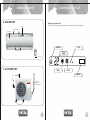
1
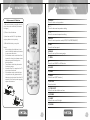
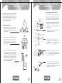
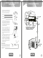
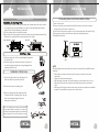
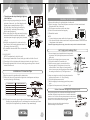
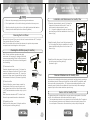
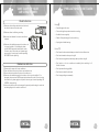
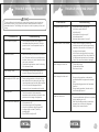
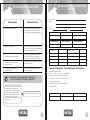
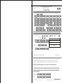
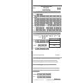
Warranty Registration System
Help us to serve you better by registering
your product for Warranty
Web
Register at www.onida.com
Telephone
Call Centre No. 0XX-39889000(0XX-STD Code of
State Capital)
Post / Visit
Post the Warranty Registration Card & Service Centre
Copy or Visit the Nearest Service Centre.
Model: INV18SLU-C8/INV18SLU-R8/INV18SLU-S8
As per Government of India’s E-Waste (Management and Handling)
Rules, 2011(effective from May 1st, 2012) the product purchased by you
is to be considered as E-Waste and cannot be disposed off with your
general household waste. It should be disposed of through the company’s
collection center so as to prevent any damage to environment
Collection Center address
Mirc Electronics Ltd.Village Kudus,Bhiwandi Wada road,
Taluka Wada., Dist. Thane - 421312,Tel no. 952525 220375/377
Visit at : www.onida.com for details about collection Centers.
We request you to make a note of the above details and support us
in our endeavour to ensure an environmental friendly nation.
AIR CONDITIONERS
The unit displayed is for representational purposes only. Actual unit may vary.
Dear customer
Congratulation on buying ONIDA Air Conditioner.
Your Air Conditioner comes with ONIDA Guarantee of Quality
as detailed in the manual.
ONIDA takes great pride in providing its customers with stateof-the-art products that adheres to international quality
standards.
ONIDA is committed to following quality policy laid by our
chairman and managing director Mr. G. L. Mirchandani.
“We are committed to quality and strive for continuous
improvement through innovation and human development to
give customer better value for money always”
ONIDA stands committed to provide the ultimate customer
satisfaction, as nothing brings us greater joy than having
satisfied customers of ONIDA.
At ONIDA, feedback and suggestions based on your product
usage experience is greatly appreciated.
Please contact to us at [email protected]
G. Sundar
Chief Executive Officer
IMPORTANT :
Please read this owner’s manual carefully and thoroughly
before installing and operating your room air conditioners.
Please retain this owner’s manual for future reference after
reading it thoroughly.
CONTENTS
Salient Features
1
Inside Overview
2
Indoor Unit Display
3
Remote Overview
4
Operations
6
General Instructions for Installation
12
Installation Sketch
15
Installation
16
Take care of your Air Conditioner
20
Precautions to be taken
23
Trouble Shooting Chart
24
Installation and Satisfaction Report
27
Warranty Terms & Conditions
29
Preventive Maintenance Service Coupon
31
Warranty Card(Customer Copy)
Warranty Card(service Center Copy)
SALIENT FEATURES
Model Code :INV18SLU-C8/INV18SLU-R8/INV18SLU-S8
• Aesthetics:a) Unique Sleek Model with High EER
• Performance:a) Imported High BTU Tropicalised Compressor
b) Trapezoidal Inner Grooved Tube
c) Large L - Shaped Condenser Coil
d) High RPM Fan Motor with High Static
• Features:a) Clean Air
b) Multi-Step Air Swing for Customized Cooling
c) Surround Air
d) Turbo
• Safety & Reliability:a) Hydrophilic Fins
b) Full Function LCD Remote
c) Special Insulation on the Air Vent
d) 5-Stage Epoxy Polyester Painting
1
INSIDE OVERVIEW
n
INDOOR UNIT DISPLAY
INDOOR UNIT
Display on the indoor unit.
For the icon of LED windows, only relevant icons will light up with their displays on.
Display
Return warm Air in
Front panel
POWER
DRY
SET TEMPERATURE( C)
Conditioned Air out
TURBO
HIGH
MED
LOW
AUTO
COOL
DRY
FAN
TEMP
MODE
ON/OFF
ENERGY
SAVER
SWING
FAN
CLEAN
AIR
TEMP.
TIMER ON/OFF
TURBO RESET LOCK
i-Cool
SELF
CLEAN
SLEEP/
DISPLAY
FOLLOW
ME
Remote controller
n
OUTDOOR UNIT
COOL
HEAT
SENSOR
Air in
Connection
pipe and
connecting wire
Exhaust Air
2
3
REMOTE OVERVIEW
REMOTE OVERVIEW
Replacement of Batteries
1) ON/OFF
Press it to start or stop operation.
1) Remove the battery cover plate from the
rear of the remote controller. (As shown in
the figure)
2) ‘’ - ‘’
Press it to decrease temperature setting.
3) ‘’ + ’’
Press it to increase temperature setting.
2) Take out the old batteries.
3) Insert two new AAA1.5V dry batteries,
and pay attention to the polarity .
2) MODE
Press it to select operation mode(AUTO/COOL/DRY/FAN/HEAT)
4) Reinstall the battery cover plate.
5) FAN
Press it to set fan speed .
Notes:
Ÿ When replacing the batteries, do not
use old or different batteries, otherwise,
it may cause malfunction.
Ÿ If the wireless remote controller will not
be used for a long time, please remove
batteries to prevent damage from
leaking batteries.
Ÿ The operation should be performed in
its receiving range.
Ÿ It should be kept 1m away from the TV
set or stereo sound sets.
Ÿ If the wireless remote controller does
not operate normally, please take the
batteries out and reinsert them after 30
seconds. If it still can't operate properly,
replace the batteries.
6)SWING
Press it to set up & down swing angle.
7) I FEEL
8)
Press it to set HEALTH or AIR function.
9) SLEEP
10) TEMP
11) QUIET
Press it to set QUIET function.]
12) CLOCK
Press it set clock.
13) T-ON T-OFF
Press it to set auto-off/auto-on timer.
14) TURBO
15) LIGHT
Press it to turn on/off the light.
16) X-FAN
4
5
OPERATIONS
OPERATIONS
1) ON/OFF
Press this button to turn on the unit. Press this button again to turn off the unit.
Ÿ This remote controller is universal . If any command
2) “ ”
Press this button to decrease set temperature. Hold it down for above 2 seconds to
rapidly decrease set temperature. In AUTO mode, set temperature is not adjustable.
Ÿ
will carry out the command as
3)“ ”
Press this button to increase set temperature. Hold it down for above 2 seconds to
rapidly increase set temperature. In AUTO mode, set temperature is not adjustable.
After energization , AUTO mode is defaulted. In AUTO mode, the set temperature
will not be displayed on the LCD, and the unit will automatically select the suitable
operation mode in accordance with the room temperature to make indoor room
comfortable.
then back to Auto.
Auto
Low speed
Low-Medium speed
indicates the guide louver swings as
9) SLEEP
Ÿ Press this button, can select Sleep 1 (
), Sleep 2 (
),Sleep 3 (
) and
cancel the Sleep,circulate between these, after electrified, Sleep Cancel is
defaulted.
Ÿ Sleep 1 is Sleep mode 1, in Cool, Dehumidify modes: sleep status after run for
one hour, the main unit setting temperature will increase 1°C, setting temperature
increased 2°C, the unit will run at this setting temperature; In Heat mode: sleep
status after run for one hour, the setting temperature will decrease 1°C, 2 hours,
setting temperature will decrease 2°C, then the unit will run at this setting
temperature.
Ÿ Sleep 2 is sleep mode 2, that is air conditioner will run according to the
presetting a group of sleep temperature curve.
Ÿ Sleep 3- the sleep curve setting under Sleep mode by DIY:
5) FAN
This button is used for setting fan speed in the sequence that goes from AUTO
to
is sent out, the unit
8)
Press this button to achieve the on and off of healthy and scavenging functions in
operation status.Press this button for the first time to start scavenging function; LCD
displays“ ”. Press the button for the second time to start healthy and scavenging
functions simultaneously; LCD displays“ ” and “ ” . Press this button for the third
time to quit healthy and scavenging functions simultaneously. Press the button for
the fourth time to start healthy function; LCD display “ ”. Press this button again to
repeat the operation above.
*Note: Only for models with heating function.
,
or
7) I FEEL
Ÿ Press this button to turn on I FEEL function. The unit automatically adjust
temperature according to the sensed temperature. Press this button again to cancel
I FEEL function.
4) MODE
Each time you press this button,a mode is selected in a sequence that goes from
AUTO, COOL, DRY, FAN , and HEAT *, as the following:
,
,
indicates the guide louver swings as
Medium speed
Medium-High speed
High speed
6)SWING
Ÿ Press this button to set up &down swing angle, which circularly changes as
below:
(1) Under Sleep 3 mode, press "Turbo" button for a long time, remote control
enters into user individuation sleep setting status, at this time, the time of
6
7
OPERATIONS
OPERATIONS
remote control will display "1hour ", the setting temperature "88" will display the
corresponding temperature of last setting sleep curve and blink (The first
entering will display according to the initial curve setting value of original
factory);
(2) Adjust "+" and "-" button, could change the corresponding setting
temperature, after adjusted, press "Trubo "button for confirmation;
(3) At this time, 1hour will be automatically increased at the timer postion on
the remote control, (that are "2hours " or "3hours " or "8hours "), the place of
setting temperature "88" will display the corresponding temperature of last
setting sleep curve and blink;
(4) Repeat the above step (2) ~ (3) operation, until 8hours temperature setting
finished, sleep,curve setting finished, at this time, the remote control will
resume the original timer display; temperature display will resume to original
setting temperature.
Ÿ Sleep3- the sleep curve setting under Sleep mode by DIY could be inquired:
The user could accord to sleep curve setting method to inquire the presetting
sleep curve, enter into user individuation sleep setting status, but do not change
the temperature, press "Turbo" button directly for confirmation. Note: In the above
presetting or enquiry procedure, if continuously within10s, there is no button
pressed, the sleep curve setting status will be automatically quit and resume to
display the original displaying. In the presetting or enquiry procedure, press
"ON/OFF" button, "Mode" button, "Timer"button or "Sleep" button, the sleep curve
setting or enquiry status will quit similarly.
12) CLOCK
Ÿ Press CLOCK button, blinking
. Within 5 seconds, pressing +or - button
adjusts the present time. Holding down either button above 2 seconds increases
or decreases the time by 1 minute every 0.5 second and then by 10 minutes
every 0.5 second. During blinking after setting, press CLOCK button again to
confirm the setting, and then
will be constantly displayed.
13) T-ON T-OFF
Ÿ Press T-ON button to initiate the auto-ON timer. To cancel the auto-timer
program, simply press this button again. After press of this button, disappears
and "ON "blinks .00:00 is displayed for ON time setting. Within 5 seconds, press
+ or - button to adjust the time value. Every press of either button changes the
time setting by 1 minute. Holding down either button rapidly changes the time
setting by 1 minute and then 10 minutes. Within 5 Seconds after setting, press
TIMER ON button to confirm. Press T-OFF button to initiate the auto-off timer. To
cancel the auto-timer program, simply press the button again.TIMER OFF setting
is the same as TIMER ON.
14) TURBO
Ÿ Press this button to activate / deactivate the Turbo function which enables th unit
to reach the preset temperature in the shortest time. In COOL mode, the unit will
blow strong cooling air at super high fan speed. In HEAT mode, the unit will blow
strong heating air at super high fan speed.
15) LIGHT
Ÿ Press LIGHT button to turn on the display's light and press this button again to
turn off the display's light. If the light is turned on ,
is displayed. If the light is
turned off,
disappears.
10) TEMP
Ÿ Press this button, could select displaying the indoor setting temperature or
indoor ambient temperature. When the indoor unit firstly power on it will display
the setting temperature, if the temperature's displaying status is changed from
other status to" ",displays the ambient temperature, 3s later or within 3s, it
receives other remote control signal that will return to display the setting
temperature. if the users haven't set up the temperature displaying status, that
will display the setting temperature.
16) X-FAN
Ÿ Pressing X-FAN button in COOL or DRY mode, the icon
is displayed and the
indoor fan will continue operation for 2 minutes in order to dry the indoor unit
even though you have turned off the unit.
After energization, X-FAN OFF is defaulted. X-FAN is not available in AUTO, FAN
or HEAT mode.
11) QUIET
Ÿ Press thisAuto
button, the Quiet status is under the Auto Quiet mode
(display " "signal ) and Quiet mode (display " " singal) and Quiet OFF (there
is no signal of " " displayed),after powered on, the Quiet OFF is defaulted.
8
9
OPERATIONS
OPERATIONS
Emergency operation
17)Combination of "+" and "-" buttons: About lock
Press "+ " and "-" buttons simultaneously to lock or unlock the keypad. If the
remote controller is locked, is displayed. In this case, pressing any button,
blinks three times.
If the wireless remote control is lost or broken, please use the manual switch button.
At this time, the unit will run at the Auto mode, but the temperature and fan speed
cannot be changed. The operation was shown as below:
18) Combination of "MODE " and "-" buttons
About switch between Fahrenheit and centigrade
At unit OFF, press "MODE" and "- " buttons simultaneously to switch between °C
and °F
19) Combination of " TEMP " and "CLOCK" buttons
About Energy-saving Function
Press “TEMP” and “CLOCK” simultaneously in COOL mode to start energysaving function. Nixie tube on the remote controller displays “SE”. Repeat the
operation to quit the function
.20) Combination of " TEMP " and "CLOCK" buttons
About 8°C Heating Function
Press “TEMP” and “CLOCK” simultaneously in HEAT mode to start 8°C Heating
Function Nixie tube on the remote controller displays “
” and a selected
temperature of “ 8°C”. (46°F if Fahrenheit is adopted). Repeat the operation to
quit the function.
Ÿ Turn on the unit: Press AUTO/STOP button to enter AUTO mode.
Ÿ The microprocessor will select the mode (COOL, HEAT, FAN) automatically
according to the room temperature for reaching comfortable effect.
Ÿ Turn off the unit: Press the AUTO/STOP button to switch off the unit.
Ÿ The operation mode is shown in the following table.
21)About Back-lighting Function
The unit lights for 4s when energizing for the first time, and 3s for later press.
Mode
Model
Temperature setting
Airflow rate
AUTO
COOLING
25℃( COOL,FAN)
AUTO
AUTO
HEAT PUMP
25℃( COOL,FAN)
AUTO
AUTO
HEAT PUMP
20℃( HEAT)
AUTO
Ÿ This switch is to be applied when the remote controller is missing.
10
11
GENERAL INSTRUCTIONS FOR
INSTALLATION
GENERAL INSTRUCTIONS FOR
INSTALLATION
Locating the Outdoor Unit
Locating the indoor and outdoor units
properly will help optimise the performance of
your airconditioner. While your Onida /
Dealer's Technician will be happy to guide you
on the best location for your airconditioner,
here are a few helpful hints.
The outdoor unit houses the compressor,
condenser fan and electrical components.
The heat removed from the room is expelled
to the atmosphere through the outdoor unit.
Locating the Indoor Unit
Once again, the Onida / dealer's Technician
will ensure optimal installation of the ODU for
you. However, the following information will
be of interest to you.
• Locate the IDU for the best cool air
circulation. Preferably, there should be
no obstructions nearby, as shown in the
adjacent figure.
• The Outdoor Unit can be mounted on a
wall, sunshade or skirting.
• Do not locate the unit directly opposite a
door which is opened frequently. The
cold air will go out of the room each time
the door is opened, as shown in the
adjacent figure.
• Ideally, the ODU should not be too
far a w a y f r o m t h e I D U ; t h e
recommended
distances are
marked in
the adjacent figure.
• Ensure that air can pass freely through
the
unit. Please allow at least 2 meters
free
space on the air outlet side, and 0.3
meters on the air inlet side.
• All indoor units will form condensate water.
Please ensure that the condensate can
be drained out of the room to a toilet /
pantry, etc. The installation engineer will
make sure that a "U" bend is provided in
the drain to prevent insects from coming
into the room through the drain tube, as
shown in the adjacent figure.
• If more than one ODU is to be installed,
they must be properly separated, so that
the warm air from the outlet of one does
not enter the inlet of the other.
12
13
GENERAL INSTRUCTIONS FOR
INSTALLATION
INSTALLATION SKETCH
• Avoid long and complicated routing
between the IDU and ODU, as
shown in the three adjacent figures.
• Too long
• Too high
• Too many bends
• The ODU must be placed on strong
frame or support. If mounted on a
wall, please ensure that the wall is
thick enough and that the frame is
supported adequately.
• Finally, it is most important for the
ODU to be easily accessible to the
service engineer. It is advisable to
discuss the same with the engineer
before deciding upon the location of
the unit.
If the ODU is to be located on a high
ledge, adequate space must be
provided for the service engineer to
service the unit. It is a good idea to
provide a catwalk (a platform)
around the unit and access door /
window to the Unit.
Electrical outlet
After the location of the outdoor unit and
indoor unit is finalised, you must provide
a suitable electrical outlet near the
indoor unit.
To
O
DU
DU
O
To
MCB
STABILISER
14
15
INSTALLATION
INSTALLATION
Connecting Indoor and Outdoor Electric Wires
Installation of Indoor Unit
1) Mounting plate should be installed horizontally. As the water tray's outlet for the indoor
unit is two-way type, during installation, the indoor unit should slightly slant to water
tray's outlet for smooth drainage of condensate.
2) Fix the mounting plate on the wall with screws.
3) Be sure that the mounting plate has been fixed firmly enough to withstand about 60 kg.
Meanwhile, the weight should be evenly shared by each screw.
09K,12K UNIT
1.Open the front panel.
2.Remove the wiring cover and wire clamp.Make the power connection cord pass
through the hole at the back of indoor unit.
3.Connect and fix the power connection cord to the terminal board. (As shown in Fig.2)
4.Fix the power connection cord with wire clamp and reinstall wiring cover.
5.Reinstall the front panel.
18K UNIT
Fig.1
1) Slant the piping hole ( ø55) on the wall slightly downward to
the outdoor side.
2) Insert the piping-hole sleeve into the hole to prevent the
connection piping and wiring from being damaged when
passing through the hole.
Fig.2
NOTE:
All wires between indoor and outdoor units must be connected by the qualified electric
contractor.
Ÿ Electric wires must be connected correctly. Improper connection may cause
malfunction.
Ÿ Tighten the terminal screws securely.
Ÿ After tightening the screws, pull the wire slightly to confirm whether it's firm or not.
Ÿ Make sure that the electric connections are earthed properly to prevent electric
shock.
Ÿ Make sure that all wiring connections are secure and the cover plates are reinstalled
properly. Poor installation may cause fire or electric shock.
Installation of Drain Hose
1) Connect the drain hose to the outlet pipe of the
indoor unit. Bind the joint with rubber belt.
2) Put the drain hose into insulating tube.
3) Wrap the insulating tube with wide rubber belt
to prevent the shift of insulating tube. Slant the
drain hose downward slightly for smooth
drainage of condensate.
Note: The insulating tube should be connected reliably
with the sleeve outside the outlet pipe. The drain hose
should be slanted downward slightly, without distortion,
bulge or fluctuation. Do not put the outlet in the water.
16
17
INSTALLATION
INSTALLATION
Ÿ The piping can be output from right, right rear,
left or left rear.
1) When routing the piping and wiring from the left or
right side of indoor unit, cut off the tailings from the
chassis when necessary(As shown in Fig.3)
A) Cut off tailing 1 when routing the wiring only;
B)Cut off tailing 1 and tailing 2 when routing
both the wiring and piping.
2) Take out the piping from body case; wrap the piping,
power cords, drain hose with the tape and then
make them pass through the piping hole. (As shown
in Fig.4)
3) Hang the mounting slots of the indoor unit on the
upper hooks of the mounting plate and check if it is
firm enough. (As shown in Fig.5)
4) The installation site should be 250cm or more above
the floor.
Installation of Out door Unit
1) Remove the handle on the right side plate of outdoor unit.
2) Take off wire clamp. Connect and fix power connection cord to the terminal board.
Wiring should fit that of indoor unit.
3) Fix the power connection cord with wire clamp.
4) Confirm if the wire has been fixed properly.
5) Reinstall the handle.
Fig.3
NOTE:
Ÿ Incorrect wiring may cause malfunction of spare part.
Ÿ After the wire has been fixed, ensure there is free space between the connection and
fixing places on the lead wire.
Schematic diagram being reference only, please refer to real product for authentic information.
Fig.4
Fig.5
Air Purging and Leakage Test
1) Connect charging hose of manifold valve to charge end of
low pressure valve (both high/low pressure valves must be
tightly shut).
2) Connect joint of charging hose to vacuum pump.
3) Fully open the handle of Lo manifold valve.
4) Open the vacuum pump for vacuumization. At the
beginning, slightly -76cmHg loosen joint nut of low
pressure valve to check if there is air coming inside (If
noise of vacuum pump has Charging hose been changed,
the reading of multi meter is 0). Then tighten the nut.
For 09/12K UNIT:
NOTE: Three situations (in front of the unit)
1) Connecting left water outlet of the unit, drain pipe is laid on the left of the unit.
2) Connecting to left or right water outlet, drain pipe is laid on the right of the unit.
3) Connecting right water outlet of the unit, drain pipe goes through hole in the wall
behind the indoor unit.
Installation of Connection Pipe
1) Align the center of the pipe flare with the related valve.
2) Screw in the flare nut by hand and then tighten the nut with spanner and torque
wrench by referring to the following:
Hex nut diameter
Tightening torque (N•m)
ø6
15~20
ø9.52
30~40
ø12
45~55
ø16
60~65
ø19
70~75
5) Keep vacuuming for more than 15mins and makesure the
reading of multi-meter is -1.0 105pa( 76cmHg)
6) Fully open high/low pressure valves.
7) Remove charging hose from charging end of low pressure
valve.
8) Tighten lid of low pressure valve. (As shown in Fig.6)
Fig.6
Outdoor Condensate Drainage (only for Heat pump unit)
During heating operation, the condensate and defrosting water should
be drained out reliably through the drain hose. Install the outdoor drain
connector in a Ø 42 hole on the base plate and attach the drain hose to
the connector so that the waste water formed in the outdoor unit can be
drained out .The hole diameter 42 must be plugged.
NOTE: Connect the connection pipe to indoor unit at first and then to outdoor unit.
Handle pi-ping bending with care. Do not damage the connection pipe. Ensure
that the joint nut is tightened firmly, otherwise, it may cause leakage.
Whether to plug other holes will be determined by the
dealers according to actual conditions.
18
19
TAKE CARE OF YOUR
AIR CONDITIONER
TAKE CARE OF YOUR
AIR CONDITIONER
Caution
Installation and Maintenance for Healthy filter
Ÿ Disconnect the power supply before cleaning and maintenance.
1) Press the clasp as shown by arrow (1) to loosen the
clasps at the lower end until a sound of “crack” is
heard; press the clasp as shown by arrow
( 2) to open the clasps at the upper end; open the
panel and then pull the filter downward to remove it. (As
shown in fig a)
Ÿ Do not splash water on the units for cleaning, as electric shocks may occur.
Ÿ Wipe the units with a dry soft cloth, or a cloth slightly moistened with water or
cleaner (not with volatile liquid such as thinner or gasoline).
Cleaning the Front Panel
Remove the front panel. Dip a piece of cloth into the water colder than 45 °C and dry it .
Then wipe the dirty part of front panel.
Note: Do not immerse the front panel into water so as to protect microprocessor
components and circuit diagram on the front panel.
2) Install the healthy filter on the air filter (as shown in fig
b). If the healthy filter fails to be installed on the air filter,
please install the healthy filter on the front case (As
shown in fig c.
Cleaning the Air Filter (every 3 months)
Note: If the air conditioner operates under dusty
environment, the frequency of cleaning air filter shall
increase correspondingly. When the filter is removed,
do not touch the fins of the indoor unit with fingers for
fear of scalding.
3) Install the air filter along arrow (1) direction and then
buckle the panel cover along arrow (2).
(As shown in fig d)
① Take down the air filter
Press the clasp as shown by arrow (1) to loosen the
lower end of clasps until a sound of “crack” is heard;
press the clasp as shown by arrow(2)to open the
upper end of clasp; open the panel and then pull the
filter downward to remove it.(As shown in figa and b)
Clean and Maintenance for Healthy Filter
Please remove the healthy filter before cleaning and reinstall it well after cleaning according to
the installation instruction. Please note that the silver ion filter shall NOT be washed by water.
Active carbon filter, photocatalytic filter,LTC catalyst and formaldehyde-killer filter can be
washed by water, but shall not be scrubbed with a brush or hard object. When washing is
completed, dry the filter in shade rather than wipe with a rag.
② Clean the air filter
Clean the filter with a vacuum cleaner or wash the
filter with water. If the filter is very dirty (such as oil
stain), please clean it with the mixture of warm water
(<45°C) and neutral abluent and then dry it up in the
shade.
Note: Never use water above 45°C to clean the air
filter as it may cause deformation or discoloration.
Service Life for Healthy Filter
The general service life for healthy filter is one year under normal operation. As to silver
ion filter, it is ineffective when the surface turns black (or green ).
Ÿ This complementary instruction is only referred for the unit with healthy filter. The graphs in
③ Reinstall the air filter
Install the air filter along arrow (1) direction and then
buckle the panel cover along arrow (2).
this complementary instruction may be different from the actual product, please refer to
the actual product. Please refer to the actual delivery for the quantity of healthy filter.
20
21
TAKE CARE OF YOUR
AIR CONDITIONER
PRECAUTIONS TO BE TAKEN
Check before Use
Do's (
1) Make sure that nothing obstructs the air inlet and
air outlet of indoor and outdoor units.
)
• Seal all air gaps in the room
• Choose the right temperature to avoid over cooling
2) Make sure there is effective grounding.
• Ventilate the room regularly.
3)Make sure the batteries for remote controller are
replaced.
• Switch off the power supply if not in use for long.
• Unplug the unit while cleaning.
4) Make sure the installation support for outdoor unit
is in good condition. If it’s damaged, please
contact ONIDA appointed maintenance center.
If there is rust on the outdoor unit, please apply
some paint to the rusty spot to avoid spreading.
BE CAREFUL when painting!
Don't's (
X)
• Don't leave the doors and windows open when the air conditioner is on.
• Don't use hot water to clean your front grill
• Don't use scouring powder, harsh soaps, wax or polish on the grill.
• Don't switch on the air conditioner immediately after switching it off.
Wait for 2 minutes.
Maintenance after Use
1) Disconnect the power for the air conditioner.
2) Clean the filter and the body of indoor and outdoor units.
3) Remove the dust and other objects on the outdoor unit.
4) Make sure the installation support for outdoor unit is in good condition. If it’s
damaged, please contact ONIDA appointed maintenance center. If there is rust on
the outdoor unit, please apply some paint to the rusty spot to avoid spreading. BE
CAREFUL when painting.
5) Indoor and outdoor units can be wrapped by special protective bags to avoid rain
and dust getting into the units to erode them.
• Don't operate with a clogged filter
• Don't block air intake & outlet vents
• Don't change setting unnecessarily.
22
23
TROUBLE SHOOTING CHART
TROUBLE SHOOTING CHART
Caution
The air conditioner is not expected to be serviced by users. Incorrect repair may
cause electric shock or fire, so please contact an authorized service center for
professional service. The following checks prior to contact may save your time and
money.
The unit does not operate:
Ÿ The unit does not operate if it is turned on
immediately after being turned off. This is to
protect the unit. You are expected to wait for
about 3 minutes.
Odours are emitted:
Ÿ
Ÿ
Ÿ
Ÿ
Ÿ
Ÿ
Remote controller is not available:
Ÿ Check if there is magnetic or electrical
Is temperature setting appropriate?
Is the inlet or outlet blocked?
Is the filter dirty?
Is the window or the door open?
Is low fan speed set?
Are there heat sources in the room?
interference near the unit that may affecting
operation of the controller. In this case, pull
the plug out and reinsert it.
Ÿ Is the remote controller within its operating
range or obstructed? Check the condition of
the batteries and replace them if necessary.
Ÿ Check if the remote controller is damaged.
Ÿ Some odours may be emitted from the indoor
unit. This is the result of room smells (such as
furniture, tobacco, etc.) which have been taken
into the air conditioner.
Ÿ Consult authorized service center for cleaning
if the odours still exist.
"Water flowing" noise:
Cooling/Heating effect is poor:
Troubleshooting
Phenomenon
Troubleshooting
Phenomenon
Water leakage of indoor unit :
Ÿ The humidity is high.
Ÿ Condensate overflows.
Ÿ Drain hose is loose.
Water leakage of outdoor unit :
Ÿ During cooling operation, condensate is
Ÿ The swishing noise like water flowing is the
sound of refrigerant flowing inside the unit.
Mist is emitted in COOL mode
Ÿ During cooling operation, a thin mist may be
generated around the pipes and connection
joints.
Ÿ During defrosting operation, the thaw water
flows out.
Ÿ During heating operation, the water on the
heat exchanger drips out.
seen emitted from the indoor unit due to high
room temperature and humidity. After a period
of time, the mist will disappear with the
decrease of room temperature and humidity.
Cracking noise:
Ÿ This is the sound of friction caused by
expansion and/or contraction of panel or other
parts due to the change of temperature.
Noise from indoor unit.
Ÿ The noise emitted when the fan or compressor
relay is switching on or off.
The unit can not be started up:
Ÿ When the defrosting operation is started or
Is the power cut off?
Is the power plug loose? (If applicable)
Is the circuit protection device tripped off?
Is voltage higher or lower? (Tested by
professionals)
Ÿ Is the TIMER correctly used?
Ÿ
Ÿ
Ÿ
Ÿ
stopped, there is a sound of refrigerant
flowing in the reverse direction.
24
25
INSTALLATION & SATISFACTION
REPORT
TROUBLE SHOOTING CHART
Troubleshooting
Phenomenon
Indoor unit cannot deliver air.
Moisture on air outlet vent.
Customer Name :
Address
Ÿ
Ÿ
Ÿ
C5: Malfunction of connector jumper:
Phone[O]
4 In DRY mode, the indoor fan will stop
blowing air for 3-12 minutes in order to
avoid condensate being vaporised again.
If unit is running under the high humidity for
a long time, the moisture will be condensed
on the air outlet grill and drip off.
Check if the connector jumper contacts
properly. If the PCB is to be replaced,
please take off the old for the new PCB.
F1: Malfunction of indoor ambient
temperature sensor
Ÿ
Check if indoor room temperature sensor is
connected properly.
F2: Malfunction of evaporator
temperature sensor
Ÿ
Check if the evaporator temperature is
connected properly.
[R]
Unit Model
Unit Serial Number
Dealer Name
Invoice Number
Date of Purchase
Date of Installation
MCB Rating
Current (Amps.)
Cable Size
Ambient Temp. ( OC)
Earthing
Room Temp. (OC)
Stabiliser
Grill Temp. (OC)
Input Voltage
Remote Operation
Customer's Response : To be filled up by the Customer
1. Installation completed within:
12hrs( ), 24 hrs( ) , 36 hrs ( ), more than 36 hrs ( )
2. How did you find the behavior of the Engineer :
Immediately stop all operations and plug out,
contact the dealer in following situations.
Excellent ( J ), Good ( K ), Not satisfied ( L )
3. Overall rating of the service:
Excellent ( J ), Good ( K ), Not satisfied ( L )
There is harsh sound during operation.
The terrible odors emitted during
operation. Water is leaking in the room.
Air switch or protection switch often
breaks. Carelessy splash water or
something into unit. There is an
abnormal heat in power supply cord and
power plug.
4. Suggestion if any:
Stop running and pull out of the plug.
Job Number
26
Engineer's Signature
Customer's Signature
27
WARRANTY TERMS
AND CONDITIONS
M/S. MIRC ELECTRONICS LTD, WARRANTS THIS ONIDA AIR CONDITIONER[(except the front grill,
knobs, remote unit and add-on plastic parts) TO THE ORIGINAL PURCHASER TO BE FREE FROM
DEFECTS IN MATERIALS AND WORKMANSHIP WITHIN ONE YEAR FROM THE DATE OF PURCHASE
AS PROVIDED IN THE WARRANTY REGISTERATION CARD.
WARRANTY FOR COMPRESSOR:
MIRC ELCTRONICS LTD, HEREAFTER WARRANTS TO THE PURCHASER OF THIS ONIDA AIR
CONDITIONER THAT FOR A PERIOD OF 12 MONTHS FROM THE DATE OF INVOICE .
WE WILL REPAIR/REPLACE THE COMPRESSOR WHICH PROVES UPON INSPECTION BY US OR ANY
OF OUR AUTHORISED SALES DEALERS TO HAVE BEEN DEFECTIVE DUE TO MANUFACTURING
DEFECT.
This warranty is subject to terms and conditions as mentioned below:
28
1.
This warranty shall be valid only for the said period of 12 months as specified above, irrespective of
whether the said unit has been in use or not for any reason whatsoever, or the unit is moved from one
location to another. Warranty does not cover accessories external to the equipment.
2.
The warranty period specified above shall include time taken for repairs, replacements, break-downs,
transit time etc. No notice of expiry period of warranty will be given by the company.
3.
This warranty shall stand automatically terminated in the event of the said unit being serviced,
repaired, installed, de-installed, re-installed or otherwise attended to by any person or organization or
agency or by the said purchaser himself other than the authorized representative of the company.
4.
Parts of the unit replaced or repaired under the terms of this warranty are warranted only for the
remaining period of the original warranty period.
5.
For attending any service call under this warranty beyond the municipal limits of the locality in which
the authorized representative/dealer is situated (outstation locations), all to and fro travelling and
other incidental expenses as prevailing from time to time incurred in connection with the visit of the
service personnel, technicians, etc shall be borne by the said purchaser and shall be payable in
advance. Additionally, all expenses incurred by the authorized representative /dealer in collecting the
said unit or any part thereof from such outstation locations and its return to the original location shall
be borne by the said purchaser.
6.
Any loss of refrigerant caused due to sabotage, improper handling or treatment , carelessness,
accident, fire, flood earthquake or any natural calamity any corrosive action on the original refrigerant
pipes, fittings, valves etc for whatever reasons, shall not be covered under this warranty.
7.
In the event of any change in the location of the unit during the warranty period, this warranty shall
become null and void unless the fact of the proposed change is communicated in writing to the
authorized dealer at least seven (7) days prior to the said change. On receipt of such information the
authorized dealer or any of its counterparts shall arrange for de-installation of the said unit on
chargeable basis. However, in the event of any damage occuring to the unit or to any of its parts during
the course of its transit by the said purchaser, repair or replacement, the said unit or any part thereof
damaged shall not be covered by this warranty.
29
Customer Identification
Number:
8. It shall be the absolute discretion of the company to a) effect the repairs or replacement of parts
whether at the site of installation or at any service centre, and b) have the job attended to either by the
Company's service personnel or its authorised dealer
Preventive Maintenance Service 1
______________________
9. This warranty is in the nature of and for the purpose of set forth herein above and in particular the
Company shall not in any event be liable for direct, indirect, incidental or consequential loss or
damages to either the said purchaser and /or his property or any other third party.
10. The AC is designed to operate at a range (230V +/- 10%). Any failure due to operation of the machine
beyond these limits will not be covered by the above warranty.
Date: ________
Customer Identification Number: ___________________________________________
Unit Model: ___________
Name of the customer: ____________________________________________________
Sr. No: _______________
Installation address: ______________________________________________________
________________________________________________________________________
Name of Serviceman:
Customer shall ensure that a stabilizer is installed in those areas where voltage is not available within
the warranty range (230V +/- 10%). The stabilizer should be of any reputed manufacturer, tested and
recommended by the Company.
________________________________________________________________________
______________________
Phone: _________________ Mobile: __________________ Fax: ________________
Date: ______ Time: _____
E-mail: _________________________________________________________________
Unit model: ____________________________ Serial Number: __________________
11. The purchaser should preserve the original invoice for necessary verification and produce, as and
when required.
Service report number: ___________________________________________________
12. Warranty null and void if:
i.
Preventive Maintenance Service
Sign. of Serviceman
Customer's Signature: _______________________ Name: _______________________
The Air Conditioner is not purchased from the authorized dealers of the company.
ii. The Service Centre copy of warranty card is not received within 10days of date of purchase at the
nearest Authorised Service Centre.
iii. Any damage is caused by accident, mishandling, tampering with installation, or negligence in
following instructions of the user manual issued by Company.
iv. Any damage is caused by improper electrical circuit outside the unit or by any defective electrical
supply
Customer Identification
Number:
v. At any time, during the warranty period if any part of the unit is tampered with, altered, repaired or
serviced by any unauthorized person, not being the authorized representative of the company or
its authorized dealers
Preventive Maintenance Service
Preventive Maintenance Service 2
______________________
Date: ________
Customer Identification Number: ___________________________________________
vi. The serail number of the unit or any part thereof is damaged , defaced, altered, obliterated , or
tampered with or removal for any reason whatsoever
Unit Model: ___________
Name of the customer: ____________________________________________________
viii. The unit is unauthorisedly moved from its original place of installation or re-installation
Sr. No: _______________
Installation address: ______________________________________________________
________________________________________________________________________
13. None of the employees and /or Authorized Dealers of the Company have any authority whatsoever to
vary the terms and conditions of this warranty.
Name of Serviceman:
14. This warranty shall be deemed to have been issued at Mumbai, state of Maharashtra and courts at
Mumbai shall have exclusive jurisdiction on matters covered by or following from this warranty, and
the original purchaser alone shall have cause of action arising out of the transaction.
________________________________________________________________________
______________________
Phone: _________________ Mobile: __________________ Fax: ________________
Date: ______ Time: _____
E-mail: _________________________________________________________________
Unit model: ____________________________ Serial Number: __________________
Service report number: ___________________________________________________
Sign. of Serviceman
Customer's Signature: _______________________ Name: _______________________
30
31
MIRC Electronics Limited
Warranty Card
Serial No.
Customer Copy
Customer Details
Title:
Mr
Ms
Mrs
M/s
Name:
Residence Address:
Dist:
Pin:
State:
Occupation:
Tel:(_____)
Res(:_____)
Code
Fax:
Code
Mobile No:
Email:
Product Details
Please Tick The Appropriate Product
Colour TV
Microwave Oven
B&W TV
DVD
Washing M/C.
AC
Plasma TV
Rear Projection TV
LCD TV
Dealer’s Name & Address
Model No:
Serial No
Please Refer Sticker On Back Cover Of Your Product
Purchase Date
Day
Month
Year
Signature
Bill No.
I Accept The Terms And Conditions of The Warranty
Customer Signature
Thank you for selecting a World Class product and we assure you that it will perform as per your expectations
We thank you for taking your time to complete this form. All Information Provided by You will be Kept Confidential.
(Please Fill In, Tear off, Fold and Mail this form to Reach us within 10 days of the Product Purchase.)
We welcome your Valuable Suggestions, if any, to Improve our Products and Services :
FOR OFFICE USE ONLY
Customer Code:
Branch:
Mirc Electronics Ltd.
Note: Company Will Not Be Responsible For The Loss Of This Form During Transit.
For Other Details on Our Products & Services Log On To www.onida.com
MIRC Electronics Limited
Warranty Card
Serial No.
Service Centre Copy
Customer Details
Title:
Mr
Ms
Mrs
M/s
Name:
Residence Address:
Dist:
Pin:
State:
Occupation:
Tel:(_____)
Res(:_____)
Code
Fax:
Code
Mobile No:
Email:
Product Details
Please Tick The Appropriate Product
Colour TV
Microwave Oven
B&W TV
DVD
Washing M/C.
AC
Plasma TV
Rear Projection TV
LCD TV
Dealer’s Name & Address
Model No:
Serial No
Please Refer Sticker On Back Cover Of Your Product
Purchase Date
Day
Month
Year
Signature
Bill No.
I Accept The Terms And Conditions of The Warranty
Customer Signature
Thank you for selecting a World Class product and we assure you that it will perform as per your expectations
We thank you for taking your time to complete this form. All Information Provided by You will be Kept Confidential.
(Please Fill In, Tear off, Fold and Mail this form to Reach us within 10 days of the Product Purchase.)
We welcome your Valuable Suggestions, if any, to Improve our Products and Services :
FOR OFFICE USE ONLY
Customer Code:
Branch:
Mirc Electronics Ltd.
Note: Company Will Not Be Responsible For The Loss Of This Form During Transit.
For Other Details on Our Products & Services Log On To www.onida.com
BUSINESS REPLY ENVELOPE
ONIDA CUSTOMER RELATION CENTRE
Adonis Electronics Pvt Ltd.
Onida House - II Mukund Ground Floor,
Mahal Industrial Estate, off. Mahakali Caves
Road, Andheri East, Mumbai, Maharashtra,
India - 400093