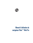
1
 IPC640 Series
Outdoor PTZ IP Cameras
Quide Guide
Manual Version: P100-20140120
© 2014, Zhejiang Uniview Technologies Co., Ltd. and its licensors All Rights Reserved No part of this manual may be reproduced or transmitted in any form or by any means without prior written consent of Zhejiang Uniview Technologies Co., Ltd. Notice The information in this manual is subject to change without notice. Every effort has been made in the preparation of this manual to ensure accuracy of the contents, but all statements, information, and recommendations in this manual do not constitute the warranty of any kind, express or implied. Technical Support [email protected] Environmental Protection This product has been designed to comply with the requirements on environmental protection. For the proper storage, use and disposal of this product, national laws and regulations must be observed. Safety and Compliance Information Conventions Used Symbol The symbols in this chapter are shown in the following table. They are used to remind the reader of the safety precautions during equipment installation and maintenance. Safety Symbol Description Generic alarm symbol: To suggest a general safety concern. Safety Symbol Description ESD protection symbol: To suggest electrostatic‐sensitive equipment. Electric shock symbol: To suggest a danger of high voltage. Safety Information WARNING! Installation and removal of the unit and its accessories must be carried
out by qualified personnel. You must read all of the Safety Instructions
supplied with your equipment before installation and operation. Warnings: z
If the product does not work properly, please contact your dealer or the nearest service center. Never attempt to disassemble the camera yourself. (We shall not assume any responsibility for problems caused by unauthorized repair or maintenance.) z
This installation should be made by a qualified service person and should conform to all the local codes. z
Make sure the power supply voltage is correct before using the camera. z
Do not drop the camera or subject it to physical shock. z
Do not touch sensor modules with fingers. If cleaning is necessary, use a clean cloth with a bit of ethanol and wipe it gently. If the camera will not be used for an extended period of time, put on the lens cap to protect the sensor from dirt. z
Do not aim the camera lens at the strong light such as sun or incandescent lamp. The strong light can cause fatal damage to the camera. z
The sensor may be burned out by a laser beam, so when any laser equipment is being used, make sure that the surface of the sensor not be exposed to the laser beam. z
While shipping, the camera should be packed in its original packing. Caution: Fiber optic ports – optical safety. Never look at the transmit laser while the power is on. Never look
directly at the fiber ports and the fiber cable ends when they are
powered on. Caution: Use of controls or adjustments to the performance or
procedures other than those specified herein may result in hazardous
laser emissions. Regulatory Compliance FCC Part 15 This equipment has been tested and found to comply with the limits for digital device, pursuant to part 15 of the FCC Rules. These limits are designed to provide reasonable protection against harmful interference when the equipment is operated in a commercial environment. This equipment generates, uses, and can radiate radio frequency energy and, if not installed and used in accordance with the instruction manual, may cause harmful interference to radio communications. Operation of this equipment in a residential area is likely to cause harmful interference in which case the user will be required to correct the interference at his own expense. This product complies with Part 15 of the FCC Rules. Operation is subject to the following two conditions: 1.
This device may not cause harmful interference. 2.
This device must accept any interference received, including interference that may cause undesired operation. LVD/EMC Directive This product complies with the European Low Voltage Directive 2006/95/EC and EMC Directive 2004/108/EC. WEEE Directive–2002/96/EC The product this manual refers to is covered by the Waste Electrical & Electronic Equipment (WEEE) Directive and must be disposed of in a responsible manner. Contents 1 Overview ............................................................................................... 1 Appearance Description ................................................................................ 1 Tail Cable ....................................................................................................... 2 Local Cache Function .................................................................................... 5 Technical Specifications ................................................................................ 6 2 Precautions ........................................................................................... 6 Precautions of Mounting .............................................................................. 7 Precautions of Maintaining ........................................................................... 8 3 Installation ............................................................................................ 9 Precautions ................................................................................................... 9 Cable Requirements .................................................................................... 11 Procedure .................................................................................................... 15 Mounting the SD Card (Optional) ............................................................... 17 High Speed Dome ............................................................................... 17 All‐weather Dome ............................................................................... 18 Infrared/Laser Dome .......................................................................... 18 Mounting the SFP Optical Module (Required for the –L Type) ................... 19 Wall Mount ................................................................................................. 20 Fast Mount.......................................................................................... 21 Conventional Mount ........................................................................... 24 Pendant Mount ........................................................................................... 28 Standing Pole Mount .................................................................................. 34 Using the Original Standing Pole ........................................................ 34 Customizing the Standing Pole ........................................................... 36 Pole Mount ................................................................................................. 38 Starting Up the Device ................................................................................ 40 i 4 Setting the Camera over the LAN ......................................................... 40 5 Accessing the Camera .......................................................................... 41 System Requirement ................................................................................... 41 Steps ............................................................................................................ 42 ii 1 Overview NOTE! This manual presents the hardware information of the device, how to
mount it, and how to quickly configure it through the web interface The IPC640 outdoor series are day & night PTZ dome network cameras. They are primarily designed to survey videos and trace remote images for large‐scale monitoring scenarios in urban security, transportation, schools, enterprise parks, buildings, gas stations, and transformer stations. The series includes domes of the high speed, all‐weather, infrared, and laser types. Appearance Description For the appearance of each product model, refer to the actual product. Figure 1‐1 Front view of a high speed dome (unit: mm) G1 ½ thread
22
38.5
298
150
218
1 Figure 1‐2 Front view of an all‐weather dome (unit: mm) G1 ½ thread
22
38.5
350
218
Figure 1‐3 Front view of an infrared/laser dome (unit: mm) G1 ½ thread
22
38.5
350
228
Tail Cable This section uses the ‐NL model as an example. For other series, all tail cables are tagged, involving the colors and signal definitions. You can connect cables by referring to Table 1‐1. 2 NOTE! z
z
The ‐NC model has an RJ45 Ethernet interface, and uses the
10M/100M Base‐TX adaptive Ethernet. The optical interface and electrical interface cannot work
simultaneously. To switch to the electrical interface, power off the
camera at first, then remove the optical module, and finally restart
the camera after inserting the cable into the electrical interface. To
switch to the optical interface, power off the camera at first, then
insert the optical module, and finally restart the camera (you do not
need to remove the electrical interface, because the optical port
takes precedence in this case). Figure 1‐4 Tail cable view Display device
1
2
Audio input (Sound pickup)
4
5
6
7
8
Alarm input (Voice activated switch)
Third‐party device connected through RS485 interface
Ground
Power adapter
Alarm output (Alarm indicator)
9
3
IP network
IP network
Network access device connected Audio output through optical (Outdoor sound interface
box)
Network access device connected through electrical interface
Table 1‐1 Description about interfaces of a tail cable Number 1
Interface
VIDEO OUT Quantity
1 Description Local video output interface (outputting composite video signals), BNC connector, 75 ohm, 1 V (P‐P) 3 Function Outputs analog video signals to analog signal display devices, like monitors. Number Interface
Quantity
Description Function Inputs audio signals or performs Intercom. Note: This interface can be used in either audio input or intercom. Inputs alarm signals. 2
AUDIO IN
1 3.5 mm audio interface, 35 k ohm, 2 V (P‐P) Note: Please use audio terminals of the mono or dual audio channels (effective signals on the left audio channel)
3
ALARM IN 2 Boolean on/off value/voltage input 4
5
6
7
24V AC 1 Ethernet optical interface 2 Power connector (3‐pin phoenix terminal) Note: The phoenix terminal connected to the yellow‐green color cable is used in grounding. 100M/1000M Base‐Fx adaptive SFP optical module with an FC connector and flanges
Note: The tail cable of an optical interface uses single mode fiber. For details, see the section "Optical fiber” Connects the power adaptor. Connects the optical interface network. AUDIO OUT 1 3.5 mm audio interface, 600 ohm, 2 V (P‐P) Outputs audio Note: Please use audio signals. terminals of dual audio channels. Ethernet interface 1 10M/100M Base‐TX adaptive Ethernet interface, RJ45 4 Connects the interface network. Number Interface
Quantity
Description Function 8
RS485 1 ‐ Interacts and controls an external device. For example, it can control a third‐party device. 9
ALARM OUT 1 Relay output Outputs alarm signals. Local Cache Function NOTE! z
z
The device supports storage by using an SD card, and the file system
of the SD card is FAT32. You can select a proper SD card by referring
to the recommended list provided by our company. To use the local cache function, disassemble the housing, and then
insert the SD card into the slot. For how to insert the SD card, see
the section "Mounting the SD Card (Optional)" To use the local cache function, ensure that the SD card has been formatted before inserting it, because the device cannot format the SD card. When the SD card is inserted, the local cache function of the device will automatically start 15 seconds after the central storage fails. Files cached to the SD card will be periodically overwritten. Therefore, you need to timely export the cache files out of the SD card, or start the video upload function to cache video backups by using the backup server managed by the central server. You can play the exported and backup videos on the web interface of the central server. 5 Technical Specifications Table 1‐2 Technical specifications Description Item High Speed Dome All‐weather Dome Power AC 24V ± 25% Maximum power consumption 42 W (including heating 25 W) Operating temperature –40°C to +70°C (–40°F to +158°F) Operating humidity 10% to 90% (non‐condensing) Weight 4.3 kg (9.5 lb.) 48 W (including heating 25 W) 5.8 kg (12.8 lb.) Infrared/Laser Dome
44 W (including heating 5 W, and infrared indicator 16 W) 5.8 kg (12.8 lb.) NOTE! z
z
This is an A‐level product, which may bring radio interference in
surroundings. In this case, you need to adopt feasible
anti‐interference solutions. The specifications are subject to changes without notice. For the
latest information, please see product datasheets. 2 Precautions It is recommended to mount the device outdoors. To avoid hazards to yourself and the device, you need to read through this chapter cautiously. 6 Precautions of Mounting z
Avoid squashing, shaking, or damping the device in transport, storage, and mounting. Keep away from vibration sources as much as possible during mounting. z
Mount the device outdoors, and protecting device connectors with effective waterproof, moisture‐proof, and dust‐proof solutions. Particularly, screws at connectors must be tightened to ensure that the device is entirely sealed. For lightning protection, you may mount the lightning arrester. z
When mounting the camera, properly mount the adapter and the bracket connector, and then fasten the tail cable unit and the adapter. Strictly follow the correct sequence. Otherwise, the tail cable could be damaged or water could intrude into the device. z
Be cautious of safety when connecting the fiber connector. Do not straightly look into output interfaces of components with light sources, such as the fiber pin section, optical module, and optical splitter. z
Use the power adapter (AC 24V 3A) delivered with the device by the mounting package. Improper power adapters may damage the device. z
Verify that the cable between the power adapter and the device is equal to or shorter than 1.5 m. If this cable is longer than 1.5 m, the voltage of the device is lowered and the device frequently will be abnormal. If it is required to lengthen the cable, lengthen the cable between the power adapter and the mains (220 V). z
Be sure to disconnect the power before moving the device, and excise caution to avoid electric shock when moving it. Once the cable is connected to the mains, the device will be powered. 7 z
When moving the device, do not hold the tail cable by hand for weight bearing. Otherwise, the cable connector of the device could be loosened. z
Do not cut off the tail cable for connection purposes. A bare tail cable may easily cause a short circuit, resulting in abnormality or damage to the device. z
When connecting to an external interface, use an existing connection terminal, and ensure that the cable terminal (latch or clamp) is in good condition and properly fastened. Ensure that the cable is not tense during mounting, with a proper margin reserved to avoid poor port contact or loosening caused by shock or shake. z
Do not expose but well protect the tail end of the tail cable. Ensure that the tail cable area is waterproof, and avoid immersing the tail cable in accumulated water.
z
To keep the housing clean, do not remove the transparent protective film in the outer layer of the housing during mounting. After confirming that the mounting is complete, remove the transparent protective film before the device is started. z
It is common that static electricity exists on the housing. To avoid dust absorption caused by static electricity, it is recommended that you wipe the surface of the housing with ESD gloves after removing the transparent protective film. . Precautions of Maintaining z
Power off the device before cleaning the housing, wipe the internal and outside surfaces by using soft dry cloth. Avoid using liquid or aerosol cleaners. z
Avoid letting the lens focus on bright‐light objects, especially the sun or other bright‐light sources. Otherwise, the imaging sensor of the device may be completely broken. 8 z
In maintenance, avoid immersing the device into foreign materials or corrosive liquids, in order to avoid dangers. Contact our company's local agent for all maintenance. Avoid opening or disassembling the protection housing by yourself, which could result in electrical shock or other dangers, and the device may be damaged. The company is not responsible for such damages. 3 Installation This chapter describes how to mount a dome with a high speed dome as an example. Refer to this chapter when mounting other domes, because their procedures are similar. Any difference shall be described. Precautions Verify device components. Before mounting, verify that all device components are available by checking the device model, component types, and quantity according to the packing list. 9 Figure 3‐1 Device components (high speed dome as an example) Top sun
shield
Bracket connector
Tail cable
Tail cable unit
Safety rope
Camera
Dome housing
Compared with the high speed dome, the all‐weather, infrared, and laser domes have different camera designs and no housing. However, other components are the same. Verify the bearing capacity of the mounted position. Verify that the mounted position can meet the bearing requirement. Otherwise, it is recommended to reinforce the mounted position for the device weight. 10 Verify the lightning protection and grounding requirements. z
Select proper lightning protection devices for the power, audio and video signals, and RS‐485 of the device. z
When grounding the device, use the grounding terminal properly. Cable Requirements Network cable 10/100 Mbps Ethernet CAT5 UTP cables are applicable to the ANSI/EIA/TIA‐568A/B and ISO/D. Eight wires in the network cable need to be inserted in parallel into the top of the cable connector. The cable connector needs to be crimped in position. After the crimping, ensure that the metal pieces of the cable connector are parallel to each other and the clamp of the cable connector is intact. Optical fiber The Ethernet optical interface connects to the single mode optical fiber. One end of the optical fiber connects to the camera, and the other end connects to a third‐party device (such as a switch). Ensure that the optical module of the third‐party device matches the camera, so that their emission wavelength and the receiver wavelength are the same. Ensure that the actual transmission distance of the optical fiber is greater than the transmission distance actually required. Ensure that the following requirements are satisfied when connecting two devices by using an optical fiber: z
When an SFP optical module is connected, the curvature of the optical fiber should not be excessively small (but should be greater than 90 degrees). 11 z
When mounting the tail cable unit, ensure that the optical fiber is not clamped by the device. Otherwise, the optical fiber could be damaged. z
Avoid excessively bending the optical fiber during mounting. If the optical fiber is excessively long, coil the optical fiber. Ensure that the coil diameter is greater than 60 mm and the curvature is greater than 90 degrees. 12 z
Select a premium‐quality fiber connector. If a non‐standard fiber connector without chamfering is used, internal ceramic sleeves such as the optical module, flange, or optical splitter could be damaged. z
Ensure that the fiber connector is in good condition, the latch is not disrupted and keeps elasticity, and the connection to the peer end is normal. z
Before connecting an optical fiber, confirm that there is no any obvious surface defect such as stain, scratch, dent, or pit. If the fiber connector, flange, or optical module is dirty, clean it with alcohol and clean cotton (or a clean cotton rod). z
When using an optical fiber to connect the device, if a flange is required for connecting the fiber connector, determine the model 13 of the flange according to the type of the fiber connector on the peer device at first, or perform cascading by directly using an optical splitter. z
When using a fiber connector to interconnect with a flange, aim the fiber connector at the slot of the flange so as to ensure proper interconnection. Power cable NOTE! Data listed in Table 3‐1 is applicable to copper cables that use AC 24V
power supply. The item Core Diameter indicates the conductor diameter.
14 Table 3‐1 Maximum length and power requirements for cables of different core diameters. Core Diameter
(Unit: mm)
Distance (Unit: m) Power (Unit: W) 0.80 1.00 1.25 2.00 30 28 45 72 183 40 21 34 54 137 50 17 27 43 110 60 ‐ 22 36 91 70 ‐ 19 31 78 80 ‐ ‐ 27 68 90 ‐ ‐ 24 61 100 ‐ ‐ 21 55 Table 3‐2 Phoenix terminals of cables Power Supply
Cable Color + / –: The anode and the cathode are not distinguished for phoenix terminals of red and black cables. AC24V 3A GND: yellow‐green color Note: GND is used to ground the device. Ensure that GND is connected to a reliable grounding point. Procedure You must power off the device when mounting the device. 15 NOTE! z
z
Brackets and accessories such as the wall mount bracket and the
pendant mount bracket may be necessary in actual mounting. For
their series, refer to the recommended list provided by our
company. The wall bearing capacity and the bracket length must satisfy
requirements of onsite mounting. You need to select a mount mode
according to the actual situations. Figure 3‐2 Mounting process Start
Verification before mounting
Whether to insert an SD card
No
Yes
Insert the SD card
No
Whether to mount an optical module
Yes
Mount the optical module
No
Whether safety requirements are met
Yes
Wall mount
Pendant mount
Yes
Corner mount
Standing pole mount
Pole mount
Verification after mounting
End
16 Mounting the SD Card (Optional) To use the local cache function, you need to insert the SD card in the device. The SD card supports hot plugging and is located inside the device. To mount the SD card, you need to remove the housing. Hot plugging is not recommended after you insert the SD card. NOTE! For details about recommended SD card specifications, contact sales or
technical support personnel. The SD card uses the FAT32 file system, and
supports only one partition. High Speed Dome 1.
Remove 5 inner hexagon screws along the housing edge. 2.
Insert the SD card and reinstall the housing. 17 All‐weather Dome 1.
Remove 4 inner hexagon screws on the front cover. 2.
Insert the SD card and reinstall the front cover. Infrared/Laser Dome 1.
Remove 4 inner hexagon screws on the front cover. 18 2.
Insert the SD card and reinstall the front cover. Mounting the SFP Optical Module (Required for the –L Type) NOTE! z
z
You need to select the optical module by referring to the
recommended list provided by our company. During the actual connection, ensure that the optical fiber plug of
the optical module matches the actual optical interface of the tail
cable. Otherwise, the optical interface of the tail cable could be
wrongly connected. You may refer to information on the label
attached to each optical interface. 1.
Remove the dustproof cover inside the tail cable unit. 19 Dustproof cover
2.
Insert the SFP optical module recommended by our company. 3.
Connect the optical fiber plug and the optical module. Wall Mount Fast mount and conventional mount are basically the same. The difference lies in operations after Step 5. Fast mount is applicable to one‐man engineering for its advantages in avoiding weight lifting and threading at heights. 20 This section describes both fast mount and conventional mount only for the wall mount. For other mount modes, only fast mount is described as an example. CAUTION! z
z
z
z
3 stainless screws that connect the tail cable unit and the camera
are crucial. Verify that they are tightened to ensure that the device
is entirely sealed. Ensure that the sun shield on the tail cable unit is
mounted in position. Fasten the screws of various joints connecting to the dome camera,
such as the bracket and the adapter ring, and ensure that no screws
are missing. For waterproofing, seal the connector between the dome and the
bracket, wall veneer slits, and leading‐out holes of the wall. The following section describes concealed‐wire mount. To
implement open‐wire mount, directly lead the cable out of the
leading‐out hole on the flank of the bracket. Fast Mount 1.
Determine positions of holes. a.
Mark positions of holes by referring to mount points of the bracket. b.
Lead cables to be connected out of wall holes. 2.
Drill wall holes. Select a drill bit matching the outer diameter of the expansion bolt. For the hole depth, refer to the bolt length 21 3.
Knock the expansion bolts, and verify that they are tightened up. 4.
Screw‐in the bracket adapter (G1 ½ male thread) to the connector of the wall mount bracket. 5.
Tighten screws (M4) at the bracket connector. 6.
Lead the tail cable through the bracket, and push up. 22 7.
Hang the suspension loops in the concave of the conversion unit, and tighten 2 M5 screws. M5 screws (2)
Concaves (2)
Suspension loops (2)
8.
Fasten the bracket to 4 expansion bolts, and lock the bracket by using flat washers, spring washers, and nuts. 9.
Hang one end of the safety rope to the camera and the other to the bracket before mounting the dome. 10. Hang the tail cable unit on the hook, push the dome upward aligning with 3 guide pins, and lock 3 stainless screws after hearing the clack. 23 Stainless screws (3)
Hook
Positioning pilot pillars (3)
Dome camera
11. Mount the top sun shield. Combine the left and right halves of the top sun shield by aligning them concurrently with the triangle icon of the dome. Then, buckle them downwards on the dome. Conventional Mount 1.
Determine positions of holes. a.
Mark positions of holes by referring to mount points of the bracket. b.
Lead cables to be connected out of wall holes. 24 2.
Drill wall holes. Select a drill bit matching the outer diameter of the expansion bolt. For the hole depth, refer to the bolt length 3.
Knock the expansion bolts, and verify that they are tightened up. 4.
Screw‐in the bracket adapter (G1 ½ male thread) to the connector of the wall mount bracket. 5.
Tighten screws (M4) at the bracket connector. 25 6.
Hang the tail cable unit on the hook, push the dome upward aligning with 3 guide pins, and lock 3 stainless screws after hearing the clack. Stainless screws (3)
Hook
Positioning pilot pillars (3)
Dome camera
7.
Hang the other end of the safety rope on the bracket, lead the tail cable through the bracket, and push up. 8.
Hang the suspension loops in the concave of the conversion unit, and tighten 2 M5 screws. 26 M5 screws (2)
Concaves (2)
9.
Mount the top sun shield. Combine the left and right halves of the top sun shield by aligning them concurrently with the triangle icon of the dome. Then, buckle them downwards on the dome. 10. Fasten the bracket to 4 expansion bolts, and lock the bracket by using flat washers, spring washers, and nuts 27 Pendant Mount 1.
Determine positions of holes. a.
Mark positions of holes by referring to mount points of the bracket. b.
Lead cables to be connected out of wall holes. 2.
Select a drill bit matching the outer diameter of the expansion bolt. For the hole depth, refer to the bolt length. 3.
Knock the expansion bolts, and verify that they are tightened up. 4.
Screw‐in the bracket adapter (G1 ½ male thread) to the connector of the pendant mountbracket. 28 5.
Tighten screws (M4) at the bracket connector. 6.
Lead the tail cable through the bracket, and push up. 7.
Hang the suspension loops in the concave of the adapter, and tighten 2 M5 screws. 29 M5 screws (2)
Concaves (2)
Suspension loops (2)
8.
Fasten the bracket to 4 expansion bolts, and lock the bracket by using flat washers, spring washers, and nuts. 9.
Hang the tail cable unit on the hook, push the dome upward aligning with 3 guide pin, and lock 3 stainless screws after hearing the clack. 30 Stainless screws (3)
Hook
Positioning pilot pillars (3)
Dome camera
10. Mount the top sun shield. Combine the left and right halves of the top sun shield by aligning them concurrently with the triangle icon of the dome. Then, buckle them downwards on the dome. 11. Corner Mount Mark positions of holes by referring to mount points of the bracket. 31 12. Drill wall holes. Select a drill bit matching the outer diameter of the expansion bolt. For the hole depth, refer to the bolt length 13. Knock the expansion bolts, and verify that they are tightened up. 14. Mount the corner mount accessory and lead the cables out. Fasten the corner mount accessory to 4 expansion bolts, and lock the accessory by using flat washers, spring washers, and nuts. 32 15. Mount the tail cable unit and the wall mount bracket by referring to 4 to 7 in the section "Fast Mount". 16. Fasten the bracket to the corner mount accessory by using 4 M8 expansion bolts, and lock the bracket by using flat washers, spring washers, and nuts. 17. Mount the dome and the top sun shield by referring to 9 to 10 in the section "Fast Mount". 33 CAUTION! z
z
When fastening the bracket, loosen cables and tighten screws. If
screws are loose, the device may fall off the mounted position. The preceding description is about concealed‐wire mount. To
implement open‐wire mount, directly lead the cable out of the
leading‐out hole on the flank of the bracket Standing Pole Mount Standing pole mount needs no bracket or accessory, and you can directly use an original pole in engineering or a customized pole. Using the Original Standing Pole You need to customize an adapter if the reserved interface of the member bar does not match the original adapter of the dome. 1.
Customize adapters, so that the dome matches with the original standing pole. 34 Original pole
Connector of the original pole
Customized conversion connector
Connector matching the original pole
M5 screw hole
G1 ½ inner thread
G1 ½ outer thread
Conversion connector delivered with the dome camera
2.
Connect and fasten the original standing pole to 2 adapters. 3.
Connect the tail cable unit, lead the tail cable into the pole, and connect all cables. See 6 to 7 in the section "Pendant Mount". 35 4.
Mount the dome and the top sun shield by referring to 9 to 10 in the section "Pendant Mount". Customizing the Standing Pole 1.
Customize a standing pole to match the dome. 36 Customized pole
M5 screw hole
G1 ½ inner thread
G1 ½ outer thread
Conversion connector delivered with the dome camera
2.
Connect and fasten the customized pole to 1 adapter. 3.
Mount the tail cable unit, the dome, and the top sun shield in sequence, same as these operations in the section "Using the Original Standing Pole". CAUTION! Seal the connector between the dome and the member bar for
waterproofing. Ensure that the sun shield on the tail cable unit is
mounted in position. 37 Pole Mount 1.
Assemble pole mount accessories, loosen 3 pole mount clamps, and insert them into holes of the pole mount bracket. Pole mount clamps (3)
Holes of the pole mount bracket (3)
2.
Tighten the clamps, and fasten the clamps to the pillar. 3.
Mount the tail cable unit and the wall mount bracket by referring to 4 to 7 in the section "Fast Mount". 38 4.
Fasten the bracket to the pole mount accessory by using 4 M8 expansion bolts, and lock the bracket by using flat washers, spring washers, and nuts. 5.
Mount the dome and the top sun shield by referring to 9 to 10 in the section "Pendant Mount". CAUTION! z
z
When fastening the bracket, loosen cables and tighten screws. If
screws are loose, the device may fall off the mounted position. The preceding description is about concealed‐wire mount. To
implement open‐wire mount, directly lead the cable out of the
leading‐out hole on the flank of the bracket. 39 Starting Up the Device After verifying the mounting, you can power on the device. Each time the device is powered on, it will perform a self‐test for checking whether the Pan/Tilt/Zoom (PTZ) is normal and basic movements such as the movement of the camera module lens are proper. After the self‐test, you can operate the device. For the detailed operation guide, see the help information on the web interface. NOTE! z
z
The flash program is programmed in the first start, prolonging the
self‐test duration. Please wait patiently. When you restart the
device, the self‐test will be quick. When the working environment temperature is lower than zero
Celsius degrees, the device will be automatically pre‐heated. When
the temperature rises above zero Celsius degrees, the device will
start the self‐test again. It takes a rather long time (at most 30
minutes) for the device to finish the pre‐heating process. Please
wait patiently. 4 Setting the Camera over the LAN To view and configure the camera via LAN (Local Area Network), you need to connect the network camera in the same subnet with that of your PC. Then, install the EZStation software to search and change the IP address of network camera. NOTE! z
z
Please contact our company to get the EZStation software. Please refer to the user manual of EZStation software for detailed
information. 1.
Connection of network camera and PC. 40 2.
Obtain the IP address of the camera for accessing via LAN. To get the IP address, you can choose either of the following methods: Use EZStation as a DHCP server that automatically assigns an IP z
address to the connected camera. Automatic detection:Use EZStation software to search online z
devices automatically. 3.
Modify the camera information. Change the IP address and subnet mask to the same subnet as that of your PC. 4.
Enter the IP address of camera in the address field of the web browser to view the live video. NOTE! z
z
The default IP address is “192.168.0.13”. The default user name is
“admin”, and password is “admin”. For accessing the camera from different subnets, please set the
gateway for the camera after you log in. 5 Accessing the Camera System Requirement Item Requirements Operation System Microsoft Windows8/Windows7/Windows XP (32‐bit or 64‐bit). Microsoft Windows7 is recommended. CPU 2.0GHz or higher, dual‐core. Intel i3 CPU or above are recommended. 41 Item Requirements Memory At least 1GB. 2GB (or higher) is recommended. Graphic card At least 128MB display memory. Mainstream discrete graphics with more than 1GB display memory are recommended. The hardware should support DirectX9.0c. Note: make sure that the latest driver is installed on graphic card. Sound card Essential. Note: the intercom and voice broadcast require the latest driver on sound card. Network card Gigabit Ethernet network cards (or higher) are recommended. Display definition
z
z
Least: 1024*768 Ideal: 1440*900 Steps 1.
Open the web browser. 2.
In the browser address bar, input the IP address of the network camera, e.g., 192.168.0.13 and press the Enter key to enter the login interface. 3.
Install the plug‐in before viewing the live video and managing the camera. Please follow the installation prompts to install the plug‐in, as shown in the figures. 42 43 NOTE! You may have to close the web browser to finish the installation of the
plug‐in. 4.
Reopen the web browser after the installation of the plug‐in and repeat the above steps 1‐2 to login. 5.
Input the user name and password. 6.
Click Login. 44 7.
View the live video and manage the camera. For detailed instructions of further configuration, please refer to the user manual of network camera. 45 BOM: 3101C034