1
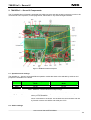
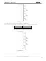
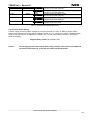
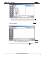
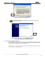
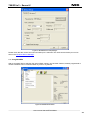
User’s Manual
78K0R/Lx3 - Sense it!
Demonstration Kit
Document No. U20191EE1V0UM00
Date Published November 2009
© NEC Electronics (Europe) GmbH
78K0R/Lx3 – Sense it!
•
The information in this document is current as of June, 2008. The information is subject to change
without notice. For actual design-in, refer to the latest publications of NEC Electronics data
sheets or data books, etc., for the most up-to-date specifications of NEC Electronics products.
Not all products and/or types are available in every country. Please check with an NEC Electronics
sales representative for availability and additional information.
•
No part of this document may be copied or reproduced in any form or by any means without the prior
written consent of NEC Electronics. NEC Electronics assumes no responsibility for any errors that may
appear in this document.
•
NEC Electronics does not assume any liability for infringement of patents, copyrights or other intellectual
property rights of third parties by or arising from the use of NEC Electronics products listed in this
document or any other liability arising from the use of such products. No license, express, implied or
otherwise, is granted under any patents, copyrights or other intellectual property rights of NEC Electronics
or others.
•
Descriptions of circuits, software and other related information in this document are provided for
illustrative purposes in semiconductor product operation and application examples. The incorporation of
these circuits, software and information in the design of a customer's equipment shall be done under the
full responsibility of the customer. NEC Electronics assumes no responsibility for any losses incurred by
customers or third parties arising from the use of these circuits, software and information.
•
While NEC Electronics endeavors to enhance the quality, reliability and safety of NEC Electronics
products, customers agree and acknowledge that the possibility of defects thereof cannot be eliminated
entirely. To minimize risks of damage to property or injury (including death) to persons arising from
defects in NEC Electronics products, customers must incorporate sufficient safety measures in their
design, such as redundancy, fire-containment and anti-failure features.
•
NEC Electronics products are classified into the following three quality grades: "Standard", "Special" and
"Specific".
The "Specific" quality grade applies only to NEC Electronics products developed based on a customerdesignated "quality assurance program" for a specific application. The recommended applications of an
NEC Electronics product depend on its quality grade, as indicated below. Customers must check the
quality grade of each NEC Electronics product before using it in a particular application.
"Standard": Computers, office equipment, communications equipment, test and measurement
equipment, audio and visual equipment, home electronic appliances, machine tools,
personal electronic equipment and industrial robots.
"Special":
Transportation equipment (automobiles, trains, ships, etc.), traffic control systems,
anti-disaster systems, anti-crime systems, safety equipment and medical equipment
(not specifically designed for life support).
"Specific": Aircraft, aerospace equipment, submersible repeaters, nuclear reactor control
systems, life support systems and medical equipment for life support, etc.
The quality grade of NEC Electronics products is "Standard" unless otherwise expressly specified in NEC
Electronics data sheets or data books, etc. If customers wish to use NEC Electronics products in applications
not intended by NEC Electronics, they must contact an NEC Electronics sales representative in advance to
determine NEC Electronics' willingness to support a given application.
(Note)
(1) "NEC Electronics" as used in this statement means NEC Electronics Corporation and also includes its
majority-owned subsidiaries.
(2) "NEC Electronics products" means any product developed or manufactured by or for NEC Electronics (as
defined above).
M8E 02. 11-1
_______________________________________________________________________________________________
User’s Manual U20191EE1V0UM00
2
78K0R/Lx3 – Sense it!
CAUTION
This is a Test- and Measurement equipment with possibility to be significantly
altered by user through hardware enhancements/modifications and/or test or
application software. Thus, with respect to Council Directive 89/336/EEC
(Directive on compliance with the EMC protection requirements), this equipment
has no autonomous function. Consequently this equipment is not marked by the
CE-symbol.
EEDT-ST-005-10
CAUTION
This equipment should be handled like a CMOS semiconductor device. The
user must take all precautions to avoid build-up of static electricity while
working with this equipment. All test and measurement tool including the
workbench must be grounded. The user/operator must be grounded using
the wrist strap. The connectors and/or device pins should not be touched
with bare hands.
EEDT-ST-004-10
For customers in the European Union only
Redemption of Waste Electrical and Electronic Equipment
(WEEE) in accordance with legal regulations applicable in the
European Union only: This equipment (including all
accessories) is not intended for household use. After use the
equipment cannot be disposed of as household waste. NEC
Electronics (Europe) GmbH offers to take back the equipment.
All you need to do is register at http://www.eu.necel.com/weee
_______________________________________________________________________________________________
User’s Manual U20191EE1V0UM00
3
78K0R/Lx3 – Sense it!
Regional Information
Some information contained in this document may vary from country to country. Before using any NEC
product in your application, please contact the NEC office in your country to obtain a list of authorized
representatives and distributors. They will verify:
•
•
•
•
•
•
Device availability
Ordering information
Product release schedule
Availability of related technical literature
Development environment specifications (for example, specifications for
third-party tools and components, host computers, power plugs, AC supply
voltages, and so forth)
Network requirements
In addition, trademarks, registered trademarks, export restrictions, and other legal issues may also vary from
country to country.
NEC Electronics Inc. (U.S.)
Santa Clara, California
Tel: 408-588-6000
800-366-9782
Fax: 408-588-6130
800-729-9288
NEC Electronics Hong Kong Ltd.
Hong Kong
Tel: 2886-9318
Fax: 2886-9022/9044
NEC Electronics (Europe) GmbH
Duesseldorf, Germany
Tel: 0211-65 03 0
Fax: 0211-65 03 1327
NEC Electronics Hong Kong Ltd.
Seoul Branch
Seoul, Korea
Tel: 02-528-0303
Fax: 02-528-4411
Sucursal en España
Madrid, Spain
Tel: 091- 504 27 87
Fax: 091- 504 28 60
NEC Electronics Singapore Pte. Ltd.
Singapore
Tel: 65-6253-8311
Fax: 65-6250-3583
Succursale Française
Vélizy-Villacoublay, France
Tel: 01-30-67 58 00
Fax: 01-30-67 58 99
NEC Electronics Taiwan Ltd.
Taipei, Taiwan
Tel: 02-2719-2377
Fax: 02-2719-5951
Filiale Italiana
Milano, Italy
Tel: 02-66 75 41
Fax: 02-66 75 42 99
NEC do Brasil S.A.
Electron Devices Division
Guarulhos, Brasil
Tel: 55-11-6465-6810
Fax: 55-11-6465-6829
Branch The Netherlands
Eindhoven, The Netherlands
Tel: 040-244 58 45
Fax: 040-244 45 80
Branch Sweden
Taeby, Sweden
Tel: 08-63 80 820
Fax: 08-63 80 388
United Kingdom Branch
Milton Keynes, UK
Tel: 01908-691-133
Fax: 01908-670-290
_______________________________________________________________________________________________
User’s Manual U20191EE1V0UM00
4
78K0R/Lx3 – Sense it!
Revision History
Date
2009-12-12
Revision
V1.00
Chapter
---
Description
First release
_______________________________________________________________________________________________
User’s Manual U20191EE1V0UM00
5
78K0R/Lx3 – Sense it!
Table of Contents
1.
Introduction ............................................................................................................................ 11
1.1
1.2
1.3
1.4
Package contents................................................................................................................................. 11
Features ................................................................................................................................................ 11
System requirements........................................................................................................................... 11
Trademarks ........................................................................................................................................... 12
2.
78K0R/Lx3 – Sense It! Components..................................................................................... 13
2.1
2.2
2.2.1
2.2.2
2.2.3
2.2.4
2.2.5
2.3
2.3.1
2.3.2
2.3.3
2.3.4
2.3.5
2.3.6
2.4
2.4.1
2.5
2.5.1
2.5.2
2.6
2.6.1
2.6.2
2.6.3
2.6.4
2.6.5
2.6.6
2.6.7
2.6.8
2.6.9
2.7
2.8
2.8.1
2.8.2
2.8.3
2.8.4
2.9
2.10
Operation mode settings..................................................................................................................... 13
Switch settings..................................................................................................................................... 13
SW1..................................................................................................................................................... 14
SW2..................................................................................................................................................... 14
SW3..................................................................................................................................................... 14
SW4 (Cursor) ...................................................................................................................................... 14
SW5..................................................................................................................................................... 14
Jumper settings ................................................................................................................................... 15
JP1 ...................................................................................................................................................... 15
JP2 ...................................................................................................................................................... 15
JP3 ...................................................................................................................................................... 15
JP4 ...................................................................................................................................................... 15
JP5 ...................................................................................................................................................... 15
JP6 ...................................................................................................................................................... 15
Connector ............................................................................................................................................. 15
FP1...................................................................................................................................................... 15
Clock...................................................................................................................................................... 15
Y1 ........................................................................................................................................................ 15
Y2 ........................................................................................................................................................ 15
Other Functions ................................................................................................................................... 16
VR1 ..................................................................................................................................................... 16
J1......................................................................................................................................................... 16
J2, J3................................................................................................................................................... 16
J4......................................................................................................................................................... 16
J5......................................................................................................................................................... 16
LED1 ................................................................................................................................................... 16
LED2 ................................................................................................................................................... 16
BUZ1 ................................................................................................................................................... 16
Universal area ..................................................................................................................................... 16
LCD Panel ............................................................................................................................................. 16
LCD Drive Voltage ................................................................................................................................ 18
Booster Type, Capacitor Split ............................................................................................................. 18
External Resistor Split-1/2 Bias Method (2 / 3 Time-Sharing).......................................................... 18
External Resistor Split-1/3 Bias Method (3, 4 Time-Sharing)........................................................... 19
External Resistor Split-1/4 Bias Method (8 Time-Sharing)............................................................... 20
Solder-Short Pads................................................................................................................................ 20
External Power Supply ...................................................................................................................... 21
3.
78K0R/Lx3 – Sense It! system configuration ...................................................................... 22
3.1
3.2
3.3
78K0R/Lx3 – Sense it!.......................................................................................................................... 22
Host computer ...................................................................................................................................... 22
Power supply via USB interface ......................................................................................................... 22
_______________________________________________________________________________________________
User’s Manual U20191EE1V0UM00
6
78K0R/Lx3 – Sense it!
4.
78K0R/Lx3 – Sense It! installation and operation............................................................... 23
4.1
4.2
Getting started...................................................................................................................................... 23
CD-ROM contents ................................................................................................................................ 23
5.
Hardware installation............................................................................................................. 24
6.
Software installation.............................................................................................................. 25
6.1
6.2
6.3
6.4
6.5
6.5.1
6.5.2
6.6
IAR Systems Embedded Workbench for 78K installation ............................................................... 25
IAR Sample project .............................................................................................................................. 26
Voice Data Conversion Tool installation ........................................................................................... 26
WriteEZ5 installation............................................................................................................................ 27
USB Driver Installation ........................................................................................................................ 27
Installation on Windows 2000 ............................................................................................................. 27
Installation on Windows XP................................................................................................................. 31
Confirmation of USB Driver Installation ............................................................................................ 33
7.
Flash Programmer WriteEZ5................................................................................................. 35
7.1
7.2
Device Setup......................................................................................................................................... 35
Using WriteEZ5..................................................................................................................................... 36
8.
Voice Data Conversion Tool CvADPCM .............................................................................. 38
9.
78K0R/Lx3 – Sense it! Sample Project................................................................................. 39
9.1
9.2
9.3
9.4
9.5
9.6
9.7
9.8
9.9
Application Overview Flowchart diagram ......................................................................................... 39
Initialization message .......................................................................................................................... 40
Clock mode ........................................................................................................................................... 40
Kitchen timer mode.............................................................................................................................. 40
Voltmeter mode .................................................................................................................................... 40
Sensor mode......................................................................................................................................... 40
LCD Evaluation mode .......................................................................................................................... 40
Voice reproduction mode.................................................................................................................... 40
Current consumption measurement mode ....................................................................................... 41
10.
IAR Embedded Workbench debug session....................................................................... 42
10.1
10.2
10.3
Settin up the Hardware for a debug session................................................................................... 42
Load the IAR Embedded Workbench sample project .................................................................... 42
Build and Debug................................................................................................................................. 43
11.
Cables ................................................................................................................................... 45
11.1
USB interface cable (Mini-B type) .................................................................................................... 45
12.
Bill of materials .................................................................................................................... 46
_______________________________________________________________________________________________
User’s Manual U20191EE1V0UM00
7
78K0R/Lx3 – Sense it!
13.
Schematics ........................................................................................................................... 48
_______________________________________________________________________________________________
User’s Manual U20191EE1V0UM00
8
78K0R/Lx3 – Sense it!
List of Figures
Figure 1: 78K0R/LH3+LCD board top view.................................................................................................13
Figure 2: LCD Panel Circuit Diagram ..........................................................................................................17
Figure 3: 78K0R/Lx3- Sense It! system configuration.................................................................................22
Figure 4: 78K0R/Lx3 – Sense It! CD-ROM contents...................................................................................23
Figure 5: 78K0R/Lx3 – Sense It! CRROM autorun.exe ..............................................................................25
Figure 6: IAR Systems Installation screen ..................................................................................................26
Figure 7: Found New Hardware Wizard (Windows 2000)...........................................................................27
Figure 8: Search Method (Windows 2000)..................................................................................................28
Figure 9: Driver File Location (Windows 2000) ...........................................................................................28
Figure 10: Address Specification 1 (Windows 2000) ..................................................................................29
Figure 11: Address Specification 2 (Windows 2000) ..................................................................................29
Figure 12: Address Specification 3 (Windows 2000) ..................................................................................30
Figure 13: Driver File Search (Windows 2000) ...........................................................................................30
Figure 14: USB Driver Installation Completion (Windows 2000) ................................................................31
Figure 15: Found New Hardware Wizard 1 (Windows XP).........................................................................31
Figure 16: Found New Hardware Wizard 2 (Windows XP).........................................................................31
Figure 17: Search Location Specification 1 (Windows XP).........................................................................32
Figure 18: Search Location Specification 2 (Windows XP).........................................................................32
Figure 19: Windows XP Logo Testing (Windows XP) .................................................................................33
Figure 20: USB Driver Installation Completion (Windows XP)....................................................................33
Figure 21: Windows Device Manager .........................................................................................................34
Figure 22: WriteEZ5 Startup.......................................................................................................................35
Figure 23: WriteEZ5 Device Setup Dialogue ..............................................................................................36
Figure 24: WriteEZ5 Device Menu ..............................................................................................................36
Figure 25: Voice Data Conversion Tool CvADPCM....................................................................................38
Figure 26: IAR Embedded Workbench Startup screen...............................................................................42
Figure 27: IAR Embedded Workbench IDE view ........................................................................................43
Figure 28: IAR Embedded Workbench Debugger Settings ........................................................................43
Figure 29: IAR C-SPY debugger window ....................................................................................................44
Figure 30: USB interface cable (Mini-B type)..............................................................................................45
_______________________________________________________________________________________________
User’s Manual U20191EE1V0UM00
9
78K0R/Lx3 – Sense it!
List of Tables
Table 1: 78K0R/Lx3 – Sense It! Switch and Jumper settings .....................................................................13
Table 2: SW1 modes ...................................................................................................................................14
Table 3: SW2 modes ...................................................................................................................................14
Table 4: SW3 modes ...................................................................................................................................14
Table 5: SW4 modes ...................................................................................................................................14
Table 6: JP1 settings ...................................................................................................................................15
Table 7: Switch settings Booster Type mode..............................................................................................18
Table 8: Switch settings External Resistor Split mode 1/2 BIAS ................................................................18
Table 9: Switch settings External Resistor Split mode 1/3 BIAS ................................................................19
Table 10: Switch settings External Resistor Split mode 1/4 BIAS ..............................................................20
Table 11: TK78K0R/LH3+LCD Solder Short Pads .....................................................................................21
Table 12: WriteEZ4 action buttons ..............................................................................................................37
_______________________________________________________________________________________________
User’s Manual U20191EE1V0UM00
10
78K0R/Lx3 – Sense it!
1. Introduction
The 78K0R/Lx3 Sense it! is an evaluation kit for development with sound systems using an 78K0R/LH3,
NEC Electronics 16bit all flash microcontroller.
The TK-78K0R/LH3+LCD board that is included in the 78K0R/Lx3 Sense it! demonstration kit, is preprogrammed with an sample application, which makes usage of the on board peripherals, like a LC display,
temperature sensor or an audio plug.
The demonstration kit also includes the CvADPCM Voice Data Conversion PC software which creates c files,
which can then be played on the TK-78K0R/LH3+LCD board using the ADPCM software library which is also
part of the kit.
1.1 Package contents
•
TK-78K0R/LH3+LCD board
•
USB cable
•
CD-ROM containing the CvADPCM Voice Data Conversion tool, WriteEZ5 and an evaluation copy
of the IAR Embedded Workbench for 78K with 16Kbyte code size limitation.
Please verify that you have received all parts listed in the package contents list attached to the 78K0R/Lx3 Sense it! demonstration kit package. If any part is missing or seems to be damaged, please contact the
dealer from whom you received your 78K0R/Lx3 - Sense it!.
1.2 Features
•
NEC Electronics all flash 16-bit 78K0R/LH3 MCU µPD78F1508
•
NEC Electronics µPD78F0730 MCU with on-chip USB interface
•
50 x 8 LCD display
•
Temperature sensor
•
Audio Plug
•
Voice data conversion tool (.wav Æ .c file) for ADPCM 78K0R audio library
•
The IAR Embedded Workbench for 78K and the IAR C-SPY debugger / simulator are included.
These packages are restricted in such that maximum program code size is limited to 16 Kbyte.
•
Full documentation is included for the NEC 78K078F1508 microcontroller, NEC 78K0 78F0730
microcontroller, IAR Systems Embedded Workbench and IAR Systems C-SPY debugger / simulator.
The 78K0R/Lx3 – Sense it! is not intended for code development. NEC does not allow and does
not support in any way any attempt to use 78K0R/Lx3 – Sense It! in a commercial or technical
product.
1.3 System requirements
A PC supporting Windows 2000, Windows XP or Windows Vista is required
HOST PC
for the IAR Systems Embedded Workbench demo-version.
A Pentium processor with at least 1 GHz CPU performance, with at least
256 Mbytes of RAM, allowing you to fully utilize and take advantage of the
product features. 500 Mbytes of free disk space and an additional 10
Mbytes of free disk space on the Windows system drive.
_______________________________________________________________________________________________
User’s Manual U20191EE1V0UM00
11
78K0R/Lx3 – Sense it!
Host interface
Note:
A web browser and Adobe Acrobat Reader to be able to access all the
product documentation.
USB interface that enables communication based on USB (Ver1.1 or later)
Updates of the IAR Embedded Workbench for 78K, documentation and/or utilities for
78K0RLX3-SENSEIT, if available, may be downloaded from the NEC WEB page(s) at
http://www.eu.necel.com/78K0RLX3-SENSEIT
1.4 Trademarks
IAR Embedded Workbench and C-SPY are registered trademarks of IAR Systems AB. Microsoft and
Windows are registered trademarks of Microsoft Corporation. Adobe and Acrobat Reader are registered
trademarks of Adobe Systems Incorporated.
All other product names are trademarks or registered trademarks of their respective owners.
_______________________________________________________________________________________________
User’s Manual U20191EE1V0UM00
12
78K0R/Lx3 – Sense it!
2. 78K0R/Lx3 – Sense It! Components
The TK-78K0R/LH3+LCD board is equipped with USB-connector and with several connectors in order to be
connected to host computers, FLASH programmer, MiniCube2 or any external target hardware.
Figure 1: 78K0R/LH3+LCD board top view
2.1 Operation mode settings
The 78K0R/Lx3 – Sense It! supports different operation modes that have to be selected by switches and
jumpers are available on the board.
Switch
SW11
SW9
Debugging/Writing
Mode
"Debug/Writer"
All ON
PC Communication
Mode
"K0R-K0/USB"
All OFF
Table 1: 78K0R/Lx3 – Sense It! Switch and Jumper settings
Debugging/Writing Mode
PC Communication Mode
Set Debugging Mode when you use ID78K0R-QB-EZ. Set Writing Mode
when you use WriteEZ5.
Connect UART0 of 78K0R/LH3 and UART6 of K0/USB (uPD78F0730)
which is mounted on the board. This enables the communication with PC
by Pseudo-connect the UART0 and COM port of PC.
2.2 Switch settings
_______________________________________________________________________________________________
User’s Manual U20191EE1V0UM00
13
78K0R/Lx3 – Sense it!
2.2.1 SW1
SW1 can set the signal that is connected to "- side" of microcontroller built-in operational amplifier 0 (AMP0 terminal).
SW1
DAC
GND
Mode
Connect D/A converter (ANO0) to "- side" of microcontroller built-in operational
amplifier 0 (AMP0 - terminal).
Connect "- side" of microcontroller built-in operational amplifier 0 (AMP0 - terminal) to
GND.
Table 2: SW1 modes
2.2.2 SW2
SW2 can set the input voltage for A/D converter (ANI1).
SW1
TEMP
Ext Volt
Mode
Connect the output of temperature sensor to A/D converter (ANI1 terminal)
Connect the voltage of J5 connector to A/D converter (ANI1 terminal)
Table 3: SW2 modes
2.2.3 SW3
SW3 can select if it uses microcontroller built-in operational amplifier 0 or not.
SW3
ON
Op-Amp 0
Use
OFF
Not Use
Remarks
Amplify 10-fold the voltage input to J5 connector by using operational
amplifier 0.
* Set SW2 to "Ext Volt" side.
Not to use operational amplifier 0
Table 4: SW3 modes
2.2.4 SW4 (Cursor)
SW4 is 4 Ways + Center-push Switch. It becomes "Low" when it is pushed or shifted to the side. It becomes
"Open" when it is released. You need to set microcontroller built-in pull-up option resistor (PU7) to "ON". (For
details about settings of microcontroller built-in pull-up option resistor, refer to the User’s manual of
78K0R/Lx3).
SW 4
1pin
2pin
3pin
4pin
5pin
6pin
Target Microcontroller Pin Name
P70/KR0
P71/KR1
P72/KR2
P74/KR3
GND
P73/KR3
Remarks
UP
CENTER PUSH
LEFT
RIGHT
DOWN
Table 5: SW4 modes
2.2.5 SW5
SW5 can select the time-sharing of LCD.
SW5
ALL OFF
ALL ON
Time-Sharing
4, 3, 2, Static
8
_______________________________________________________________________________________________
User’s Manual U20191EE1V0UM00
14
78K0R/Lx3 – Sense it!
2.3 Jumper settings
2.3.1 JP1
JP1 is a switch jumper to select the power supply.
Position
1-2
2-3
Function
USB power supply connected (USB1)
Power supply via J2 (VDD) or J3 (GND)
Table 6: JP1 settings
2.3.2 JP2
JP2 is the point to measure consumption current of microcontroller AVREFP terminal. Take off short pin and
connect an ampere meter to measure the current. As the sample software uses VREFOUT, take off the
short pin. It is opened as default.
2.3.3 JP3
JP3 is the point to measure consumption current of microcontroller AVDD0 terminal. Take off short pin and
connect an ampere meter to measure the current. It is shorted as default.
2.3.4 JP4
JP4 is the point to measure consumption current of microcontroller AVDD1 terminal. Take off short pin and
connect an ampere meter to measure the current. It is shorted as default.
2.3.5 JP5
JP5 is the point to measure consumption current of microcontroller VDD terminal. Take off short pin and
connect an ampere meter to measure the current. It is shorted as default.
2.3.6 JP6
JP6 is the point to measure consumption current of microcontroller EVDD terminal. Take off short pin and
connect an ampere meter to measure the current. It is shorted as default.
2.4 Connector
2.4.1 FP1
This is the interface to connect MINICUBE2.
The connector itself is not attached. If you wish to connect MINICUBE2, you need to solder the 16pin
connector on FP1.
2.5 Clock
2.5.1 Y1
This is the main clock. 20MHz Ceralock (Murata: CSTLS20M0X51-B0) is mounted.
2.5.2 Y2
This is the sub clock. 32.768KHz oscillator (SII: SSP-T7-FL 3.7pF) is mounted.
_______________________________________________________________________________________________
User’s Manual U20191EE1V0UM00
15
78K0R/Lx3 – Sense it!
2.6 Other Functions
2.6.1 VR1
This is the volume control for J1.
2.6.2 J1
J1 is the stereo mini-jack for audio output. Audio is output on left side only.
2.6.3 J2, J3
External power supply connectors. For further information refer to the “External Power Supply” chapter.
2.6.4 J4
This is the pad for a battery socket (on the back side of the board). For further information refer to the
“External Power Supply” chapter.
2.6.5 J5
J5 is the terminal to connect voltage to be measured. It can apply a voltage 0V-2.0V without using
operational amplifier and 0.02V-0.22V with using operational amplifier.
2.6.6 LED1
LED1 is LED controlled by "P33/INTP3/TI07/TO07". It lights by outputting "Low".
2.6.7 LED2
This is the Power LED. It lights up if power is supplied to the board.
2.6.8 BUZ1
BUZ1 is a piezoelectric buzzer (TDK: PS1240P02BT) controlled by "P32/INTP5/TI01/TO01/PCLBUZ0". It
sounds by outputting about 4 KHz pulse.
2.6.9 Universal area
The kit has the universal area. Users can use this to develop custom circuit.
2.7 LCD Panel
The LCD panel has following specifications.
•
TN liquid crystal
•
1/8DUTY
•
5V Drive
•
8COM x 50SEG = 400 segment
_______________________________________________________________________________________________
User’s Manual U20191EE1V0UM00
16
78K0R/Lx3 – Sense it!
Figure 2: LCD Panel Circuit Diagram
_______________________________________________________________________________________________
User’s Manual U20191EE1V0UM00
17
78K0R/Lx3 – Sense it!
2.8 LCD Drive Voltage
The allowed LCD drive voltages can be selected by switches mounted to the TK-78K0R/LH3+LCD board.
2.8.1 Booster Type, Capacitor Split
Set the switches as shown below.
SW7
SW6
SW8
All OFF
Any
Any
Table 7: Switch settings Booster Type mode
A 0.47µF capacitor is connected to each terminal, following methods can be selected.
・ Booster Type-1/3 bias method
・ Booster Type-1/4 bias method
・ Capacitor Split-1/3 bias method
2.8.2 External Resistor Split-1/2 Bias Method (2 / 3 Time-Sharing)
Set the switches as shown below. It is connected with 100KΩ of resistance (diagram below).
SW7
SW6
SW8
All ON
1/2 Bias Mode
Other Mode
Table 8: Switch settings External Resistor Split mode 1/2 BIAS
_______________________________________________________________________________________________
User’s Manual U20191EE1V0UM00
18
78K0R/Lx3 – Sense it!
2.8.3 External Resistor Split-1/3 Bias Method (3, 4 Time-Sharing)
Set the switches as shown below. It is connected with 100KΩ of resistance (diagram below).
SW7
SW6
SW8
All ON
Other Mode
Other Mode
Table 9: Switch settings External Resistor Split mode 1/3 BIAS
_______________________________________________________________________________________________
User’s Manual U20191EE1V0UM00
19
78K0R/Lx3 – Sense it!
2.8.4 External Resistor Split-1/4 Bias Method (8 Time-Sharing)
Set the switches as shown below. It is connected with 100KΩ of resistance (diagram below).
SW7
SW6
SW8
All ON
Other Mode
1/4 bias Mode
Table 10: Switch settings External Resistor Split mode 1/4 BIAS
2.9 Solder-Short Pads
With using the solder-short pad to cut/connect the circuit, users can customize the circuit. The solder-short
pad looks like the picture below. To open, use cutter to cut the dent part. To short, put solder on the pad.
Solder-short pad
(Open)
Solder-Short
Pad Name
P20~P27
Solder-short pad
(Short)
Default
Short
P32
Short
P33
Short
P110
Short
Connection
Short
Open
Short
Open
Short
Open
Short
Connect port2 to analog circuit
Use port2 for other purpose
Connect port32 to the driver of buzzer
Use port32 for other purpose
Connect port33 to the driver of LED1
Use port33 for other purpose
Connect port110 to analog circuit
_______________________________________________________________________________________________
User’s Manual U20191EE1V0UM00
20
78K0R/Lx3 – Sense it!
P111
Short
P150
Short
P157
Short
VLC0
Short
Open
Short
Open
Short
Open
Short
Open
Short
Open
Use port110 for other purpose
Connect port111 to SW1
Use port111 for other purpose
Connect port150 to analog circuit
Use port150 for other purpose
Connect port157 to GND
Use port157 for other purpose
Connect to VDD when SW4-1 is set to "ON"
Connect VLC0 not to VDD
Table 11: TK78K0R/LH3+LCD Solder Short Pads
2.10 External Power Supply
A Power supply other than USB is available by using the terminal (J2: VDD, J3: GND) or button battery
socket (not mounted) on the back side of substrate. Set the JP1 to 2-3 short and connect a stabilized power
supply to the terminal pins J2 (VDD) and J3 (GND). Also, you can mount battery socket on J4 to supply
power from battery.
Support battery socket: KEYSTONE 1060
Caution:
Do not supply power from terminal while using a battery. If the terminal (J2: VDD) and
the anode of the battery is connected, the battery will be destroyed.
_______________________________________________________________________________________________
User’s Manual U20191EE1V0UM00
21
78K0R/Lx3 – Sense it!
3. 78K0R/Lx3 – Sense It! system configuration
The 78K0R/Lx3 – Sense It! starter kit system configuration is given in the diagram below
Figure 3: 78K0R/Lx3- Sense It! system configuration
3.1 78K0R/Lx3 – Sense it!
The 78K0R/Lx3 – Sense It! is a demonstration kit for the 78F1508 16-bit microcontroller of the 78K0R family.
The demonstration board is connected to the host system via USB interface cable. The host system may be
used for On-Chip debugging by using the IAR C-SPY debugger and to allow execution of application
programs on 78K0R/Lx3 – Sense It! starter kit.
78K0R/Lx3 – Sense It! runs the microcontroller at 20 MHz operating speed in normal operation mode.
3.2 Host computer
The USB host interface enables communication to the 78K0R/Lx3 – Sense It! board. The μPD78F0730
78K0 8-Bit microcontroller with on-chip USB interface and the NEC virtual UART driver allows application
software to access the µPD78F1508 device in the same way as it would access a standard RS232 interface.
The NEC virtual UART driver appears to the windows system as an extra Com Port, in addition to any
existing hardware Com Ports.
3.3 Power supply via USB interface
The TK-78K0R/LH3+LCD board is powered by the USB interface. Optional the power supply can be applied
via the connectors J2 (VDD) and J3 (GND) or an external battery mounted to J4 on the back side of the
starter kit board.
_______________________________________________________________________________________________
User’s Manual U20191EE1V0UM00
22
78K0R/Lx3 – Sense it!
4. 78K0R/Lx3 – Sense It! installation and operation
4.1 Getting started
The 78K0R/Lx3 – Sense It! is delivered with a pre-programmed sample application, that makes use of the
available peripherals of the TK-78K0R/LH3+LCD board. The CD comes with a 16KB code size limited
version of the IAR Embedded Workbench and a software tool to generate a .c file out of a .wav audio file.
The also include sound library enables the user to program and hear the wanted sound file via a audio
output connected to the audio jack mounted on the board.
4.2 CD-ROM contents
CD-ROM ROOT
- Acrobat Reader for 32Bit Windows OS
78K0R/Lx3 - Sense It!
Acrobat
Doc
-
Documentation
Driver
-
TK-78K0R/LH3+LCD device driver files
IAR Embedded Workbench
-
IAR Embedded Workbench for 78K
sample program
-
Example project for the 78K0R/Lx3 - Sense
It! Demonstration Kit
WriteEZ5
-
Flash Programmer WriteEZ5 incl. PRM file
for µPD78F1508
Figure 4: 78K0R/Lx3 – Sense It! CD-ROM contents
_______________________________________________________________________________________________
User’s Manual U20191EE1V0UM00
23
78K0R/Lx3 – Sense it!
5. Hardware installation
After unpacking the 78K0R/Lx3 – Sense It! demonstration kit, connect the board via connector USB1 to your
host computer using the provided USB interface cable. When TK-78K0R/LH3+LCD board is connected, the
USB driver needs to be installed on the host machine. Please refer to the following USB Driver Installation.
_______________________________________________________________________________________________
User’s Manual U20191EE1V0UM00
24
78K0R/Lx3 – Sense it!
6. Software installation
The 78K0R/Lx3 – Sense It! package comes with the following software packages:
•
IAR Systems Embedded Workbench for 78K 16KB code size limited, including C compiler,
assembler, linker, librarian and IAR C-SPY debugger / simulator
•
Voice Data Conversion Tool CvADPCM
•
WriteEZ5 flash programmer software including the PRM file for μPD78F1508
•
IAR Embedded Workbench for 78K sample project
Figure 5: 78K0R/Lx3 – Sense It! CRROM autorun.exe
6.1 IAR Systems Embedded Workbench for 78K installation
To install the IAR Systems Embedded Workbench for 78K including C-SPY debugger / simulator press the
regarding button from the Autorun of the CDROM provided within the 78K0R/Lx3 – Sense It! package. The
installation can also be started by executing the Autorun.exe program in the directory ”\IAR Embedded
Workbench\” of the CDROM.
When running the autorun.exe the following screen appears.
_______________________________________________________________________________________________
User’s Manual U20191EE1V0UM00
25
78K0R/Lx3 – Sense it!
Figure 6: IAR Systems Installation screen
Note:
Before installing the IAR Embedded Workbench for 78K 16KB code size limited version a
license number and key has to be requested from IAR Systems. Therefore please follow the
IAR online registration. The license number and key shall be provide within a view minutes
after the request is submitted.
To install the IAR Embedded Workbench for 78K just press the regarding button “Install IAR Embedded
Workbench ®”. The setup dialogues will guide you through the installation process. For further information
about the IAR Embedded Workbench installation refer to the InstallationGuide_IAR_EWB.ENU.pdf in
the directory ”\IAR Systems\” of the CDROM.
6.2 IAR Sample project
To copy the IAR sample project just press the regarding button “IAR sample project”. The setup dialogues
will guide you through the copying process. The installation can also be started by executing the
IAR_sample_project.exe in the directory ”\sample program” of the CDROM.
6.3 Voice Data Conversion Tool installation
To install the CaADPCM Voice Data Conversion Tool just press the regarding button from the Autorun of the
CD-ROM provided within the 78K0R/Lx3 – Sense It! package. The setup dialogues will guide you through
the installation process. The installation can also be started by executing the CvADPCM Voice Data
Conversion Tool v140.exe in the directory ”\Voice Data Conversion Tool” of the CDROM.
_______________________________________________________________________________________________
User’s Manual U20191EE1V0UM00
26
78K0R/Lx3 – Sense it!
6.4 WriteEZ5 installation
To install the WriteEZ5 just press the regarding button from the Autorun of the CD-ROM provided within the
78K0R/Lx3 – Sense It! package. The setup dialogues will guide you through the installation process. The
installation can also be started by executing the WriteEZ5_v100_EE.exe in the directory ”\WRITEEZ5”
of the CDROM.
6.5 USB Driver Installation
In order to use the TK-78K0RKE3L board, the USB driver needs to be installed on the host machine. Install
the driver according to the following procedure:
Installation on Windows 2000
Installation on Windows XP
Page 27
Page 31
6.5.1 Installation on Windows 2000
1.
When the TK-78K0R/LH3+LCD board is connected with the host machine, the board is
recognized by <Plug and Play>, and the wizard for finding new hardware is started. Click
Next>.
Click.
Figure 7: Found New Hardware Wizard (Windows 2000)
2.
Following the window below is displayed. So, check that "Search for a suitable driver ..." is
selected, then click Next>.
_______________________________________________________________________________________________
User’s Manual U20191EE1V0UM00
27
78K0R/Lx3 – Sense it!
Check that "Search for a
suitable driver ..." is selected.
Click.
Figure 8: Search Method (Windows 2000)
3.
Check the "Specify a location" check box only, then click Next>.
Check that "Specify a
location" only is checked.
Click.
Figure 9: Driver File Location (Windows 2000)
4.
Locate to the folder "CDROM:\Driver”.
_______________________________________________________________________________________________
User’s Manual U20191EE1V0UM00
28
78K0R/Lx3 – Sense it!
Locate to “CDROM:\Driver”
Figure 10: Address Specification 1 (Windows 2000)
5.
The setup information file “MQB2ALL.inf” is automatic selected, then click Open to proceed
within driver installation.
Click.
Figure 11: Address Specification 2 (Windows 2000)
6.
After the location of the USB driver has been specified click OK to proceed.
_______________________________________________________________________________________________
User’s Manual U20191EE1V0UM00
29
78K0R/Lx3 – Sense it!
Click.
Figure 12: Address Specification 3 (Windows 2000)
7.
Click Next>.
Figure 13: Driver File Search (Windows 2000)
8.
Click.
Click Finish to complete the installation of the USB driver.
Click.
_______________________________________________________________________________________________
User’s Manual U20191EE1V0UM00
30
78K0R/Lx3 – Sense it!
Figure 14: USB Driver Installation Completion (Windows 2000)
6.5.2 Installation on Windows XP
1.
When the TK-78K0R/LH3+LCD board is connected with the host machine, the board is
recognized by Plug and Play, and the wizard for finding new hardware is started. At first the
hardware wizard will ask if windows should search on the windows update web, check "No,
not this time" and then click Next>.
Check that "No, not this time"
is selected.
Click.
Figure 15: Found New Hardware Wizard 1 (Windows XP)
2.
Check that "Install from a list or specific location (Advanced)" is selected, then click Next>.
Check that "Install from a list or
specific ..." is selected.
Click.
Figure 16: Found New Hardware Wizard 2 (Windows XP)
3.
Check that "Search for the best driver in these locations." is selected. Select the "Include
this location in the search:" check box and then click Browse.
_______________________________________________________________________________________________
User’s Manual U20191EE1V0UM00
31
78K0R/Lx3 – Sense it!
<1> Check that "Search for the
best driver in these locations."
is selected.
<2> Check "Include this
location in the search:"
only.
<3> Click.
Figure 17: Search Location Specification 1 (Windows XP)
4.
Locate the folder "C CDROM:\Driver” and click OK.
Figure 18: Search Location Specification 2 (Windows XP)
5.
As shown below, "NEC Electronics Starter Kit Virtual UART has not passed Windows Logo
testing to verify its compatibility with Windows XP." is displayed. Click Continue Anyway.
_______________________________________________________________________________________________
User’s Manual U20191EE1V0UM00
32
78K0R/Lx3 – Sense it!
Click.
Figure 19: Windows XP Logo Testing (Windows XP)
6.
After the installation of the USB driver is completed the window below is displayed. Click
Finish to close the hardware wizard.
Click.
Figure 20: USB Driver Installation Completion (Windows XP)
6.6 Confirmation of USB Driver Installation
After installing the USB driver, check that the driver has been installed normally, according to
the procedure below. When using the TK-78K0R/LH3+LCD board the “NEC Electronics Starter
Kit Virtual UART” should be present like in the figure below.
Please check in the Windows "Device Manager" within the Windows Properties (“Hardware”
tab), that the driver is installed normally.
_______________________________________________________________________________________________
User’s Manual U20191EE1V0UM00
33
78K0R/Lx3 – Sense it!
Check that "NEC Electronics
Starter Kit Virtual UART (COM?)"
is present.
Figure 21: Windows Device Manager
_______________________________________________________________________________________________
User’s Manual U20191EE1V0UM00
34
78K0R/Lx3 – Sense it!
7. Flash Programmer WriteEZ5
WriteEZ5 is flash programming software to flash hex files to the related device. For installation information
refer to the chapter WriteEZ5 installation.
Figure 22: WriteEZ5 Startup
7.1 Device Setup
To provide all necessary information about the device to be programmed, only the corresponding flash
parameter file must be loaded. The parameter file (*.prm) for the µPD78F1508 is located on the CDROM in
the same folder as the WriteEZ5 setup file. Please use the menu “Device -> Setup…“ to open the following
dialogue and the button “PRM File Read” to select the parameter file.
_______________________________________________________________________________________________
User’s Manual U20191EE1V0UM00
35
78K0R/Lx3 – Sense it!
Figure 23: WriteEZ5 Device Setup Dialogue
Please check that the correct host communication port is selected. The used communication port can be
seen in the Windows Device Manager.
7.2 Using WriteEZ5
After a successful device selection the internal flash memory can be blank-checked, erased, programmed or
verified. WriteEZ5 can be controlled either by menu or by buttons
Figure 24: WriteEZ5 Device Menu
_______________________________________________________________________________________________
User’s Manual U20191EE1V0UM00
36
78K0R/Lx3 – Sense it!
device setup button
load file button
blank check button
erase button
program button
verity button
Autoprocedure button
Table 12: WriteEZ4 action buttons
WriteEZ5supports Intel-Hex and Motorola S-record file formats as input file.
_______________________________________________________________________________________________
User’s Manual U20191EE1V0UM00
37
78K0R/Lx3 – Sense it!
8. Voice Data Conversion Tool CvADPCM
The Voice Data Conversion Tool CvADPCM is a tool that generates ADPCM data to implement a voice
application for the 78K0R/Lx3 microcontroller. Running on Microsoft WindowsTM, this tool converts WAV files
(PCM) into ADPCM (40 kbps to 16 kbps). The result of conversion is output as a source code that can be
read by the IAR Embedded Workbench for 78K.
ADPCM stands for adaptive differential PCM, and it supports the following algorithms.
•
CCITT Recommendation G.726 (40 kbps, 32 kbps, 24 kbps, 16 kbps)
•
NEC Electronics’ ADPCM-SP (32 kbps, 24 kbps, 16 kbps)
•
NEC Electronics’ ADPCM-SP2 (32 kbps, 16 kbps)
Note: CvADPCM can be used on a PC on which Windows XPTM or Windows VistaTM correctly runs.
This tool may not run on Windows 2000 because it uses the functions of DirectX.
Figure 25: Voice Data Conversion Tool CvADPCM
For further information regarding the CvADPCM tool please refer to the Application note CvADPCM
(U19015EJ2V0AN00.pdf) available on CDROM in the directory “Doc\CvADPCM”.
_______________________________________________________________________________________________
User’s Manual U20191EE1V0UM00
38
78K0R/Lx3 – Sense it!
9. 78K0R/Lx3 – Sense it! Sample Project
The 78K0R/Lx3 – Sense it! Demonstration kit sample project which is already programmed into the device is
written to make use of the available peripherals of the TK-78K0R/LH3+LCD board. The startup sample
makes use of a lot of different on chip peripherals of the 78K0R/Lx3 microcontroller 78F1508, so the real
time clock, A/D- and D/A converter, Key interrupt, Timer Array Unit and LCD controller are used.
The user can use sample functions for these peripherals like Clock display, Kitchen timer, Voltmeter,
Temperature measuring, Sound reproduction or current measuring of the different operation modes of the
target device. Furthermore the LCD mounted on the TK-78K0R/LH3+LCD is used to guide the user through
the available functions of the sample project.
9.1 Application Overview Flowchart diagram
Start
Initialization of
Hardware
Initialization of
each module
Power supply
state detection
Timer
processing
Key
processing
Top
menu
Clock mode
processing
Voltmeter mode
processing
Kitchen timer mode
processing
LCD evaluation mode
processing
Sensor mode
processing
Mode processing for
Current consumption
measurement
Voice reproduction
mode processing
Kitchen Timer
alarm processing
Key
processing
_______________________________________________________________________________________________
User’s Manual U20191EE1V0UM00
39
78K0R/Lx3 – Sense it!
For information how to navigate through the program please refer to Sample_project_operation_manual.pdf
available on the CDROM in the directory “\Doc\TK78K0R”.
9.2 Initialization message
When the board is connect to a power supply the LCD will show up a welcome message “ALL FLASH
MICROCONTROLLER 78K0R/LH3 STARTER KIT” as a ticker until the Cursor is used to leave this init
screen.
9.3 Clock mode
The Clock mode can be separate in two parts, showing the actual time and setting up the time in a 12 - or 24
hour mode. The clock is displayed on the LCD and uses the RTC of the device. To generate an accurate
clock reference timing the 78K0R/Lx3 sub-clock of 32.768 KHz is used.
9.4 Kitchen timer mode
The kitchen timer symbolizes a countdown timer, where the user has to set up the countdown time first and
then starts the countdown. The LCD is updated by using the interval interrupt of the real time counter. After
the countdown has expired a short sound is played through the audio output of the demonstration kit.
9.5 Voltmeter mode
The Voltmeter mode gives the user 2 possibilities of shown measurement results. In both cases the 12bit
A/D converter is used. The 1st mode only shows the voltage, measured on the A/D converter input. The 2nd
mode displays the A/D converter result added with the inverted offset input voltage 200mV, amplified 10
times. The measurable voltage range is 0.02V-0.22V with used operational amplifier and 0V – 2V without
used operational amplifier.
9.6 Sensor mode
When the Sensor mode is selected the LCD shows up the measured temperature. The temperature is
measured by a temperature sensor that is connected to an A/D converter input of the 78F1508
microcontroller. The result of the 12 bit A/D conversion is used as PWM duty cycle to control the brightness
of LED1. The temperature can be displayed on the LCD in °Celsius as well as in Fahrenheit. The
temperature range that can be measured is between - 35°C (- 30°F) and 100°C (212°F).
9.7 LCD Evaluation mode
First of all you can change the contrast of the LCD within this mode. Beside this a display test can be
performed. The selected contrast is hold even if the LCD Evaluation mode is left.
The 2nd part of the LCD Evaluation mode is a display test where the different LCD driver modes can be
tested.
When performing the display tests please make sure that the right hardware setup is selected for the tested
mode. To check the hardware setup, please refer to chapter 2.8 LCD driver voltage.
Note:
The Capacitance display test can not be performed if the board is battery driven.
9.8 Voice reproduction mode
In the Voice reproduction mode a pre-programmed sound sequence can be played via the 12- or 10- bit D/A
converter of the microcontroller. To be able to hear the sound an audio device has to be plugged in the Jack
connector J1 on the TK-78K0R/LH3+LCD board. If the kitchen timer countdown is elapsed during the sound
reproduction the alarm sound is skipped and is played after the sound sequence is finished. The ADPCM
library which is included in the sample project is used to extend the sound data. For further information
regarding the ADPCM library please refer to the regarding Application Note (U19000EJ2V0AN00.pdf)
available on the CDROM in the directory “\Doc\CvADPCM”.
_______________________________________________________________________________________________
User’s Manual U20191EE1V0UM00
40
78K0R/Lx3 – Sense it!
9.9 Current consumption measurement mode
The Current consumption measurement mode gives the user the possibility to measure the actual current
consumption. Therefore the microcontroller can be set in different operating modes.
•
Main Run:
The microcontroller runs in normal operation but kitchen timer and other functions are stopped. LCD
does not display anything while it is functioning. Make a key input to back to normal mode.
•
Sub Run:
Stop kitchen timer, other functions, and main system clock, and switch the CPU clock to sub system
clock. LCD does not display anything while it is functioned. Make a key input to back to normal mode.
•
Main Halt:
Stop kitchen timer and other functions, and change to HALT mode. LCD does not display anything
while it is functioning. Make a key input to back to normal mode.
•
Sub Halt:
Stop kitchen timer, other functions, and main system clock, switch the CPU clock to sub system
clock, and change to HALT mode. LCD does not display anything while it is functioning. Make a key
input to back to normal mode.
•
Sub Halt + RTC:
Stop kitchen timer, functions other than LCD, and main system clock, switch the CPU clock to sub
system clock, and change to HALT mode. Display the LCD with constant periodic interrupt (each
0.5sec). Make a key input to back to normal mode.
•
Stop:
Stop kitchen timer and other functions, and change to STOP mode. LCD does not display while it is
functioning. Make a key input to normal mode. The clock is cleared before functioning.
_______________________________________________________________________________________________
User’s Manual U20191EE1V0UM00
41
78K0R/Lx3 – Sense it!
10. IAR Embedded Workbench debug session
The pre-programmed sample application is also provided as an IAR Embedded Workbench project on the
starter kit CDROM.
10.1 Setting up the Hardware for a debug session
To be able to perform a C-SPY debug session on the 78K0R/Lx3 Sense it! demonstration kit board please
make sure that the hardware is set up correctly. Therefore please refer to chapter 2.1 and set the hardware
to the Debugging/Writing Mode.
10.2 Load the IAR Embedded Workbench sample project
After copying the IAR sample project to the hard drive of your Host PC as described in chapter 6.2 you shall
be able to run this sample project.
To start the IAR Embedded Workbench 16K Kickstart for 78K click Start Æ All Programs Æ IAR Systems
Æ IAR Embedded Workbench for 78K v4.62 Kickstart Æ IAR Embedded Workbench.
The Embedded Workbench Startup screen comes up. To open the sample project workspace press the
Open existing workspace button and locate the 78K0RLx3-SENSEIT_sample.eww file in the sample
program folder.
Figure 26: IAR Embedded Workbench Startup screen
The project shall show up on the left side of the IAR Embedded Workbench window in the Workspace view.
_______________________________________________________________________________________________
User’s Manual U20191EE1V0UM00
42
78K0R/Lx3 – Sense it!
Figure 27: IAR Embedded Workbench IDE view
10.3 Build and Debug
Before build the project please check that MINICUBE is selected as Debugger Driver. Therefore open the
Debugger settings by clicking Project Æ Options and select the Category Debugger.
Figure 28: IAR Embedded Workbench Debugger Settings
_______________________________________________________________________________________________
User’s Manual U20191EE1V0UM00
43
78K0R/Lx3 – Sense it!
When the TK-78K0R/LH3+LCD evaluation board is connected correctly to the Host PC and MINICUBE is
selected as Debugger driver you shall be able to build, download and debug the sample project. Therefore
) or click Project Æ Download and Debug. After
just press the Download and Debug button (
downloading the sample project to the target device the IAR C-SPY debugger shows up and the program
shall be stopped at the beginning of the main() function.
Figure 29: IAR C-SPY debugger window
. Now you can control the application as described in the
To run the application press the Run button
chapter above. Furthermore all standard IAR C-SPY debugger functionalities for a MINICUBE debug
session are available. For further information about the IAR tools please refer to the regarding IAR User’s
manuals available in the IAR Embedded Workbench (Help).
_______________________________________________________________________________________________
User’s Manual U20191EE1V0UM00
44
78K0R/Lx3 – Sense it!
11. Cables
11.1 USB interface cable (Mini-B type)
Figure 30: USB interface cable (Mini-B type)
_______________________________________________________________________________________________
User’s Manual U20191EE1V0UM00
45
78K0R/Lx3 – Sense it!
12. Bill of materials
No.
1
2
3
4
Qty
1
1
1
19
5
6
7
8
9
10
11
12
13
14
15
1
1
1
1
1
1
0
4
1
1
8
16
17
18
19
20
21
22
23
24
25
26
27
28
29
30
31
32
33
1
0
1
6
1
1
1
0
0
1
1
1
1
1
1
6
1
12
34
35
36
37
38
39
40
41
42
43
44
45
46
47
48
49
50
51
52
53
54
55
56
1
1
1
1
1
2
1
6
4
1
2
5
1
3
1
1
1
1
1
2
1
1
1
Reference
BUZ1
C1
C2
C3,C4,C7,C9,C10,C13,C14,
C17,C22,C32,C36,C37,C38,
C42,C43,C44,C45,C46,C47
C5
C6
C8
C11
C12
C15
Reference (not mounted)
C16,C19,C24,C30,C34
C18,C23,C31,C35
C20
C21
C25,C26,C27,C28,C29,C33,
C39,C41
C40
FP1
JP1
JP2,JP3,JP4,JP5,J5,JP6
J1
J2
J3
J4
J6
LCD1
LED1
LED2
L1
L2
MR1
R1,R2,R6,R7,R8,R15
R3
R4,R11,R14,R18,R20,R21,
R22,R23,R28,R32,R38,R40
R5
R9
R10
R12
R13
R16, R17
R19
R24,R25,R27,R33,R37,R39
R26,R30,R31,R36
R29
R34,R35
SW1,SW2,SW3,SW6,SW8
SW4
SW5,SW7,SW9
SW10
SW11
USB1
U1
U2
U3,U6
U4
U5
U7
Manufacturer Part No.
PS1240P02BT
F930J476MAA
0.01µF
0.1µF
150pF
1µF / 16V
0.0082µF
0.0039µF
330pF
F931C106MAA
xxx / Dip
10µF / 16V
4pF
3pF
0.47µF
4.7µF / 25V
HIF3FC-16PA-2.54DSA
FFC-3AMEP1
FFC-2AMEP1
LGY6502-0900FC
T-16-Red
T-16-Black
1060
FFC4-4AMEP1
A45A005X
SLR-56DU
PG1112H
MPZ1608R391A
BLM41PG750S
CN1E4K-105J
43K
22
100K
220K
1K
1.2K
300
430K
0
330
1.5K
10K
100
27
SSSS213000
SKRHABE010
CHS-04B
SKQMBB
SSSS223600
UX60A-MB-5ST
LM4890M
S-8120CNB
SN74LVC2G07DCK
uPD78F1508GF
SN74LVC2G125DCU
UPD78F0730MC
Manufacturer
TDK
nichicon
nichicon
HIROSE
HONDA
HONDA
SMK
SATO PARTS
SATO PARTS
Keystone
HONDA
JSC
ROHM
ROHM
TDK
Murata
KOA
ALPS
ALPS
COPAL
ALPS
ALPS
HIROSE
NS
SII
TI
NECEL
TI
NECEL
_______________________________________________________________________________________________
User’s Manual U20191EE1V0UM00
46
78K0R/Lx3 – Sense it!
57
58
59
60
61
62
1
1
1
1
1
1
U8
U9
VR1
Y1
Y2
Y3
SN74LVC1G125DCK
SN74LVC2T45DCU
CT6-EP20K(203)
CSTLS20M0X51-B0
SSP-T7-FL 3.7pF
CSTCE16M0V53-R0
TI
TI
COPAL
Murata
SII
Murata
_______________________________________________________________________________________________
User’s Manual U20191EE1V0UM00
47
78K0R/Lx3 – Sense it!
13. Schematics
Please find the schematics attached to this document. To open the attachments view in the Adobe Reader
press the paper clip in the lower left corner of the program window. To open the attachment, double click the
78K0RLH3_LCD.pdf.
_______________________________________________________________________________________________
User’s Manual U20191EE1V0UM00
48
78K0R/Lx3 – Sense it!
[MEMO]
_______________________________________________________________________________________________
User’s Manual U20191EE1V0UM00
49


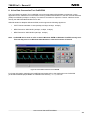


![[S30830T-CPE] Users Manual: CPE83SUE](http://vs1.manualzilla.com/store/data/005890174_1-2a1526c3cbd1c0db150881a0418c3ddc-150x150.png)