1
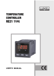
TEMPERATURE CONTROLLER RE55 TYPE USER’S MANUAL CONTENTS 1. APPLICATION............................................................................5 2. CONTROLLER SET...................................................................5 3. CONTROLLER PREPARATION to WORK................................5 3.1. Safety..................................................................................5 3.2. Controller installation in the panel.......................................6 3.3. Electrical connection...........................................................7 3.4. Installation recommendations.............................................7 4. WORK STARTING.....................................................................8 4.1.Kind of execution..................................................................8 4.2. Controller service................................................................9 4.3. Setting of setpoint value . .................................................10 5. PROGRAMMING of ONTROLLER PARAMETERS - CONFIGURABLE EXECUTION.............................................10 5.1. Scheme of the controller menu.........................................10 5.2. Setting change..................................................................14 5.3. List of parameters.............................................................15 6. CONTROLLER INPUTS and OUTPUTS.................................17 6.1. Measuring input.................................................................17 6.2. Output ..............................................................................18 7. CONTROL ..............................................................................19 7.1. ON-OFF control.................................................................19 7.2. PID control........................................................................19 8. ALARMS - CONFIGURABLE EXECUTION.............................20 9. MANUFACTURER’S SETTINGS - CONFIGURABLE EXECUTION.............................................21 10. SELECTION of PID PARAMETER SETTINGS - CONFIGURABLE EXECUTION.............................................21 10.1. Autotuning.......................................................................21 10.2. Correction of PID settings ..............................................24 11. ERROR SIGNALLING..............................................................24 12. TECHNICAL DATA...................................................................26 13. CONTROLLER EXECUTION CODES.....................................29 14. MAINTENANCE and GUARANTEE........................................30 1. APPLICATION The R55 controller is a microprocessor controller with an analog setting and digital measurement of the measured value. The controller controls the temperature in objects through switching on and off the electrical control device, in accordance with the definite set point by the controller. The controller co-operates directly with RTD and TC temperature sensors. The controller is destined to control temperature in plastics industry, food and dehydration industries, and everywhere when it is necessary to stabilize temperature changes. 2. CONTROLLER SET The controller set is composed of: 1. controller.................................................... 1 pc 2. plug with 16 screw terminals..................... 1 pc 3. holder to fix in the panel............................ 2 pcs 4. user’s manual............................................ 1 pc 5. guarantee card.......................................... 1 pc. When unpacking the controller, please check whether the type and option code on the data plate correspond to the order. 3. CONTROLLER PREPARATION to WORK 3.1. Safety The RE55 controller meets requirements concerning the safety of electrical measuring devices in automatics acc. to the EN 61010-1 standard, requirements concerning the immunity against electromagnetic interference acc. to the EN 61000-6-2 standard and the emission of electromagnetic interference occurring in industrial environments, acc. to the EN 61000-6-4 standard. When connecting the supply, one must remember that a switch or a circuit-breaker should be installed in the building. This switch should be located near the device, easy accessible by the operator, and marked as an element switching the device. 3.2. Controller Installation in the panel Fix the controller in the panel by means of two screw holders included in the standard accessory set, acc. to the fig. 1. The panel hole should be 91+0,6 x 91+0,6 mm. The thickness of the material which the panel is made of, cannot exceed 6 mm. Fig. 1. Way of controller fixing. Controller overall dimensions are presented below, on the fig. 2. Fig.2. Overall dimensions of the RE55 controller. 3.3. Electrical connections Carry out electrical connections in compliance with the fig. 3. Fig. 3. Scheme of electrical connections. Note: 1. When connecting the Pt100 sensor in two-wire version, one must short terminals 1 and 2. 2. One cannot connect any wires to not used controller terminals. 3.4. Installation recommendations The RE55 controller fulfils requirements concerning immunity against electromagnetic interference in industrial environments acc. to binding standards. In order to obtain a full fastness of the controller against electromagnetic interference in an unknown environment interference level, it is recommended to observe following principles: - do not supply the controller from the network near devices generating high impulse interference, - apply network filters, - apply metallic shields in the shape of tubes or braided screens to conduct supplying wires, - wires supplying the measuring signals should be twisted in pairs, and for resistance thermometers in a 3-wire connection, twisted with wires of the same length, cross-section and resistance, and led in a shield as above, - all screens should be one-side earthed, and led the nearest possible to the controller, - apply the general principle that wires leading different signals should be led the farthest possible between them (not less than 30 cm), and their crossing executed at a right angle. 4. WORK STARTING After the correct installation and supply connection, the controller carries out the display test and displays the type of controller on the upper display inscription re55, the program version and next, the measured value. A character message informing about abnormalities may appear on the display (table 4). 4.1. Kind of execution The controller is available in following executions: ON-OFF controller - analog setting of the set point and digital measurement of the measured value, - control algorithm of on-off type with hysteresis set on 2.0C. PID controller - analog setting of the set point and digital measurement of the measured value, - control algorithm of PID type with manufacturer’s setting depending on the execution (see table 1). Configurable controller - analog setting of the set point and digital measurement of the measured value, - control algorithm of on-off or PID type and parameters set by the user, - programming of controller parameters by means of and push-buttons, - autotuning function, - alarm output, - programmable change of control between heating and cooling, - possible safe-guard of parameters through a password. 4.2. Controller service The view of the frontal controller plate in the on-off or PID execution is presented on the fig.4a, and in the configurable execution with push-buttons and the alarm, on the fig.4b. a) b) Fig. 4. Frontal plate of the controller. Following elements are situated on the frontal plate of the controller: 1 - display of the measured value, 2, 3 - hand-setting knob with the indicating dial to set the set point value, 4 - green diode signalling the output state, 5 - red diode signalling the alarm state, 6, 7 - push-buttons. 4.3. Setting of the set point value The setting of the set point is carried out after pressing the internal part to the external part of the hand-setting knob. The controller displays automatically the set point value in case of the potentiometer movement. The return to display the measured value follows after 5 seconds since the potentiometer movement steady-state. In the controller version with push-buttons, the monitoring of the set point is possible after pressing the push-button. During the display of the set point, the display pulsates. 5. PROGRAMMING of CONTROLLER PARAMETERS - CONFIGURABLE EXECUTION 5.1. Scheme of the controller menu The scheme of the controller menu is presented on the fig.5. After pressing and holding down the push-button during at least 2 seconds, it is possible to program parameters. The transition between parameters is carried out by means of the push-button. The description of parameters is contained in the table 1. The return to the normal working mode follows after the simultaneous pressure of and push-buttons or automatically after 30 seconds since the last push-button pressure. Some parameters may be invisible. It depends on the current controller configuration. 10 Fig.5. Menu of the controller service. 11 Fig. 5. Menu of the controller service. One can protect by a code the access to parameters. If the parameter is set (the seCU parameter is higher than zero), one must give it during the entry to the menu. First, the inscription code appears and after the release of the push-button, one can introduce the code value. If an incorrect code value will be introduced, the inscription err appears on the display and the user will be able only to review parameter values. The introduction of the safety code is shown on the fig.6. 12 Fig. 6. Introduction of the access code. 13 5.2. Setting change The change of the parameter setting begins after pressing the push-button. By means of the push-button one can increase the flickering digit or the non-numerical parameter, and by the pushbutton, one can transit between digits or accept the non-numerical parameter. The change cancellation follows after the simultaneous pressure of and push-buttons, or automatically after the laps of 30 sec. since the last push-button pressure. The way to change the setting is shown on the fig. 7. Fig. 7 . Setting change of numerical and textual parameters. 14 5.3. List of parameters The list of controller parameters is presented in the table 1. List of configuration parameters Parameter symbol alg Parameter descriptions Controller algorythm Range of parameters changes oNof: on-off control algorythm pid: PID control algorythm Table 1 Manufacturer’s setting oNof 6) pid 7) pb Proportional band 1) 0.1...999.9 °C PB FABR acc. to table 2 ti Integration timeconstant 1) 0...9999 s (0 - unit disabled) 300 td Differentiation timeconstant 1) 0.0...999.9 s (0 - unit disabled) 60.0 to Pulse repetition period 1) 0.5...99.9 s 20.0 Hy Hysteresis 2) 0.2...99.9 °C 2.0 out Configuration of the control output dir: control of cooling type inu: control of heating type inu parameter hidden at on-off control, parameter hidden at proportional control, 3) parameter visible when there is an appropriate configuration of the input alarm, 1) 2) 15 Parameter symbol aLty Parameter descriptions Configuration of the alarm output Range of parameters changes none: disabled AHi: absolute upper alarm Alo: absolute lower alarm duHi: relative upper alarm dulo: relative lower alarm duin: absolute internal Manufacturer’s setting none alarm duou: absolute external alarm aLsp Alarm set value 3) MIN...MAX acc. to table 2 aLdu Deviation of the set value for the relative alarm 3) -199.9...199.9 °C 0.0 aLHy Hysteresis for the alarm 3) 0.2...99.9 °C 2.0 shjf Shift of the measured value -99.9...99.9 °C 0.0 dp Position of the decimal point for the measured value 4) 0_dp: without decimal point 1_dp: 1 decimal place seCU Safety code 5) 0...9999 0 1_dp 0 only for executions with resolution 0.1 (see table 5), parameter hidden in the mode of parameter review and only for readout, 6) for the execution, in execution code: on-off controller and configurable controller, 7) for the execution, in execution code: PID controller. 4) 5) 16 Parameters depending on the measuring range Table 2 Sensor MIN MAX PB FABR Resistance thermometer Pt100 -50...100°C -50.0 100.0 15.0 Resistance thermometer Pt100 0...100°C 0.0 100.0 10.0 Resistance thermometer Pt100 0...150°C 0.0 150.0 15.0 Resistance thermometer Pt100 0...250°C 0.0 250.0 20.0 Resistance thermometer Pt100 0...400°C 0.0 400.0 25.0 Resistance thermometer Pt100 0...600°C 0.0 600.0 30.0 Thermocouple type J 0...250°C 0.0 250.0 20.0 Thermocouple type J 0...400°C 0.0 400.0 25.0 Thermocouple type J 0...600°C 0.0 600.0 30.0 Thermocouple type J 0...900°C 0.0 900.0 40.0 Thermocouple type K 0...600°C 0.0 600.0 30.0 Thermocouple type K 0...900°C 0.0 900.0 40.0 Thermocouple type K 0...1300°C 0 1300 45.0 Thermocouple type S 0...1600°C 0 1600 50.0 6. CONTROLLER INPUTS and OUTPUTS 6.1. Measuring inputs The controller has one measuring input to which, one can connect a resistance thermometer or thermocouple sensor acc. to the execution code. for the resistance thermometer Pt100 in a three-wire connection, the compensation of the line resistance is carried out automatically. In the two-wire connection, one can take into consideration that the line resistance introduces an additional measurement error. For thermoco- 17 uples, the compensation of the reference junction is carried out automatically. An additional parameter is the number of digits after the decimal point, parameter dp which defines if the measured temperature is to be shown with a place after the decimal point (only for execution with resolution 0.1C). The correction of the measured value indication is carried out by the shif parameter. 6.2. Output The controller has one control output. On this output, it is possible to select the on-off control or proportional PID control. For the proportional control, one must additionally set the pulse repetition period. The pulse repetition period is the time which go by, between successive switching of the output on during the proportional control. The length of the pulse repetition period must be chosen depending on dynamic properties of the object and suitably to the actuator. It is recommended to use solid-state relays (SSR) for quick processes. The relay output is used to control contactors in slow-speed processes. The use of a too high pulse repetition period to control high-speed processes may give undesirable effects in the shape of oscillations. Theoretically, the lower pulse repetition period, the better control is, however for the relay output it should be as high as possible in order to lengthen the relay life. Recommendations concerning the pulse repetition period Output Electromagnetic relay Transistor output 18 Table 3 Pulse repetition period to Load recommended >20s min. 10 s 2A/230V a.c. or contactor min. 5 s 1A/230V a.c. 1...3 s solid-state relay (SSR) 7. CONTROL 7.1. On-off control (ON-OFF) The choice of the on-off control type requires following settings, the alg parameter must be set on oNof, the hysteresis value given in the parameter - Hy, and the way of the output operation established by the parameter - out. The operation way of the output on heating (fig.8) is set by the parameter out=inu, and on cooling by the parameter out=dir. Fig.8. Operation way of the output heating type. 7.2. PID control The choice of the PID or also PI, PD or P control type requires following settings, the alg parameter must be set on pid, and suitably set parameter values - proportional range (pb), integrating unit (ti) and differentiating unit (td). The switching of the given unit off consists on setting the parameter on zero. The operation way of the output on heating is chosen by setting the out=inu, parameter, and on cooling by setting the parameter out=dir. The next parameter to set, is the pulse repetition period (to). 19 8. Alarms - configurable execution Absolute upper (aLty = AHi) Relative lower (aLty = dulo) Absolute lower (aLty = Alo) Relative lower (aLty = dulo) Relative upper (aLty = duHi) Relative internal (aLty = duin) Relative upper (aLty = duHi) Relative external (aLty = duou) Fig.9. Kinds of alarms. The alarm configuration requires the choice of the kind of alarm through setting the aLty parameter. Accessible types of alarms are given on the fig.9. The set point value for absolute alarms is the value defined by the aLsp parameter, and for relative alarms, that is the deviation from the set point value in the main line - aLdu parameter. The alarm hysteresis, that is the zone around the set point value, in which the output state is not changed, is defined by the aLHy parameter. 20 9. MANUFACTURER’S SETTINGS - CONFIGURABLE EXECUTION Manufacturer’s settings can be restored during the supply switching on, by holding down and push-buttons till the moment, when the fabr inscription appears on the upper display. 10. SELECTION of PID PARAMETER SETTINGS - CONFIGURABLE EXECUTIONS 10.1. Autotuning The controller has the function of automatc selection of the PID setting. Obtained settings ensure in most of cases an optimal control. To start the autotuning, one must transit to the atparameter (acc.to the fig. 5) and hold down the push-button during at least 2 sec. The parameter is accessible only for the proportional control (alg = pid). However it is inaccessible when giving the incorrect safety code (if it was activated). The flickering decimal point from the left side of the display informs about the autotuning function activity. The autotuning duration time depends on dynamic properties of the object and may lasts maximally 10 hours. During the autotuning or directly after it, over-regulations can arise, for this reason, one must set a lower set point value, if it is possible. After the autotuning termination, calculated PID settings are stored in the non-volatile memory and the control process starts with new settings. The autotuning process may not start or be broken without calculation od PID settings, if: - the measured value is higher than the set point value (for control of heating type), – the difference between the set point value and the measured value is lower than 5% of the measuring range, – the time of the preliminary object stabilization or the admissible time of the autotuning duration will be exceeded, – when a controller supply decay occurs, – any push-button has been pressed, – the set point value has been changed, 21 – calculated parameter values are beyond the range. In such cases, the control with previous PID settings will start. The controller, depending on the control deviation, chooses the response method to the unitary jump or the oscillation method. The response method to the unitary jump is chosen when the difference between the set point value and measured value is at least 20% of the controller measuring range. Response method to the unitary jump The autotuning by the response method to the unitary jump is composed of following stages: – switching the control signal off and stabilization of the object temperature (since 2 min till 3 hours), – switching the control signal on (100 % ) and determination of the object characteristic ( max. 10 hours), – calculation of PID settings and their storage in the non-volatile memory, – beginning of the PID control with new settings. 22 Fig.10. Selection of settings by the response method to the unitary jump On the object characteristic presenting the controlled quantity in the function of time, one may see the delay time of the object to and the maximal temperature accretion (which is calculated from the dependence: Vmax = ∆PV max ∆t ). PID settings are calculated acc. to following equations: Pb = 1.1 • Vmax • T0 - proportional range ti = 2.4 • T0 - integration time-constant td = 0.4 • T0 - differentiation time-constant Oscillation method around the set point value The autotuning by the oscillation method is composed of following stages: – on-off control acc. to fig.11, – calculation of PID settings and their storage in the non-volatile memory, – beginning of the PID control with new settings. Fig.11. Selection by the oscillation method. PID settings are calculated acc. to given formula: Pb = P ti = T td = 0.25 * T 23 10.2. Correction of PID settings PID parameters interact between them and, one must introduce changes of only one parameter. The better is to match parameters, changing the value into a twice higher or twice lower value. During changes, one must respect following principles: a) Slow response of the object: – decrease the proportional range, – decrease integration and differentiation time-constants. b) Over-regulations: – increase the proportional range, – increase the differentiation time. c) Oscillations: – increase the proportional range, – increase the integration time, – decrease the differentiation time. d) Instability: – increase the integration time. 11. ERROR SIGNALLING Character messages Error code lerr 24 Cause Exceeding of the measuring range down or shorting in the sensor circuit Table 4 Procedure Check, if the appropriate sensor was connected and if input signals are situated in the appropriate range , if yes, check if there is not a short-circuit in the sensor circuit. Herr ------- Exceeding of the measuring range down or shorting in the sensor circuit Exceeding of the set value range down Exceeding of the set value range up aTer Autotuning finished with failure eRad Input discalibrated eRsp Input of the set point value discalibrated eRee Error of the readout verification from the non-volatile memory Check, if the type of the selected sensor is compatible with the connected sensor; check if values of input signals are situated in the appropriate range , if yes, check if there is not a break in the sensor circuit. Check, if the setting potentiometer index is not situated beyond the dial range. Check, if the setting potentiometer index is not situated beyond the dial range. Check the cause of breaking the tuning process in the autotuning point. Connect again the controller supply, If that not help, contact the nearest service workshop. Connect again the controller supply, If that not help, contact the nearest service workshop. Connect again the controller supply, if that not help, contact the nearest service workshop. The exploitation in this state may cause its unforeseen behaviour. 25 12. TECHNICAL DATA Range, resolution and based intrinsic error for different executions Sensor type Range °C Resolution °C Table 5 Intrinsic error °C Resistance thermometer (acc. EN 60751+A2), measuring current 0.25 mA Pt100*) -50...100 0...100 0...150 0...250 0...400 0...600 0.1 0.1 0.1 0.1 0.1 0.1 ±0.8 ±0.5 ±0.8 ±1.3 ±2.0 ±3.0 Thermocouple of J type (acc. EN 60584-1) Fe-CuNi 0...250 0...400 0...600 0...900 0.1 0.1 0.1 0.1 ±2.0 ±2.0 ±3.0 ±4.0 Thermocouple of K type (acc. EN 60584-1) NiCr-NiAl 0...600 0...900 0...1300 0.1 0.1 1 ±3.0 ±4.0 ±6.0 Thermocouple of S type (acc. EN 60584-1) PtRh10-Pt *) 0...1600 1 ±8.0 Sensor line resistance <10 /wire, one must make the connection with wires of identical cross-section and length 26 Potentiometric setting of the set point: - resolution of the set point setting 0.1% of the controller range - difference between the set point and the value set on the graduation <2% of the controller range Measurement time 0.5 s Error detection in the measurement circuit: - thermocouple, Pt100 measuring range exceeding Control algorithm: - P, PD, PI, PID, ON-OFF with hysteresis Setting range of controller parameters - See table 1 Kinds of outputs: for control output: - relay without voltage - logic voltage for alarm output: - relay without voltage normally open contact (NOC) load capacity1 A/230 V, Output operation: - reverse - direct for heating for cooling change-over contact load 2 A/230 V 5 V voltage, 10 Ω rresistance limiting the current (without isolation from the sensor side for alarm output) Signalling: - switching the main output on - switching the main output off Rated operating conditions: - supply voltage - supply voltage frequency - ambient temperature - storage temperature - relative air humidity 85...253 V a.c. / d.c. 40...440 Hz 0...23...50°C -20...+70°C < 85% (without condensation) 27 - external magnetic field - preliminary warm-up time - operating position - resistance of wires connecting the resistance thermometer with the controller < 400 A/m 30 min. any <10 Ω/wire Consumption < 4 VA Weight < 0.3 kg Overall dimensions 96 ´ 96 ´ 65 mm Panel cut-out 91+0.6 ´ 91+0.6 mm Protection degree ensured by the housing acc. to EN 60529: - from the frontal plate side IP 40 - from terminal side IP 20 Additional errors in rated operating conditions caused by: - compensation of the thermocouple reference junction temperature change ≤ 2°C, - changes of the RTD line resistance ≤ 50% of the intrinsic error - change of ambient temperature ≤ 100% of the intrinsic error /10 K. Safety requirements acc. to EN 61010-1: - isolation between circuit basic, - installation category III, - pollution degree 2, - maximal working voltage in relation to earth: - for the supply circuit 300 V - for input circuits 50 V - altitude above sea level under 2000 m Electromagnetic compatibility: - immunity acc. to EN 61000-6-2 - emission acc. to EN 61000-6-4 28 13. controller execution codes The coding way is given in the table 6 Temperature controller RE55 - Input: Pt100/1,3850 Fe-CuNi (J) NiCr-NiAl (K) PtRh10-Pt (S) on order * Table 6 X X X X X -50...100C............................01 0...100C................................02 0...150C................................03 0...250C................................04 0...400C................................05 0...600C................................06 0...250C................................07 0...400C................................08 0...600C................................09 0...900C................................10 0...600C................................ 11 0...900C................................12 0...1300C..............................13 0...1600C..............................14 . .............................................99 Kinds of execution: on-off controller ........................................................... 1 PID controller .............................................................. 2 controller configurable by push-buttons and with an alarm...3 Control output relay: relay................................................................................... 1 voltage 0/5V....................................................................... 2 Version: standard...................................................................................00 custom-made...........................................................................99 Additional acceptance test requirements: without additional requirements.......................................................8 with a quality inspection certificate.................................................7 acc. customer’s requirements **..................................................... X *) - After agrement with the manufacturer **) - The code will be established by the manufacturer 29 EXAMPLE OF ORDER The code: RE55 02 3 1 00 8 means: RE55 - temperature controller of RE55 type 02 - input Pt100, range: 0...100°C 3 - execution: controller configurable by push-buttons and with an alarm 1 - control output: relay 00 - standard version 8 - without an additional quality certificate. 14. MAINTENANCE and GUARANTEE The RE55 controller does not require any periodical maintenance. In case of some incorrect controller operations: 1. After the dispatch date and in the period stated in the guarantee card One should return the instrument to the Manufacturer’s Quality Inspection Dept. If the instrument has been used in compliance with the instructions, the Manufacturer warrants to repair it free of charge. The disassembling of the housing causes the cancellation of the granted guarantee. 2. After the guarantee period: One should turn over the instrument to repair it in a certified service workshop. We reserves the right to make changes in design and specifications of any products as engineering advances or necessity requires. 30 31 RE55-07 Lubuskie Zak³ady Aparatów Elektrycznych - LUMEL S.A. ul. Sulechowska 1, 65-022 Zielona Góra, Poland Tel.: (48-68) 32 95 100 (exchange) Fax: (48-68) 32 95 101 www.lumel.com.pl e-mail:[email protected] Export Department: Tel.: (48-68) 329 53 02 or 53 04 Fax: (48-68) 325 40 91 e-mail: [email protected] 32