1
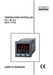
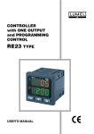
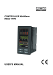
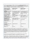
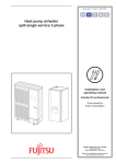
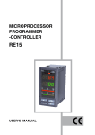
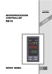
MICROPROCESSOR PROGRAMMERCONTROLLER RE20 USERS MANUAL 1 CONTENTS 1. Controller description ....................................................... 4 2. Controller set .................................................................... 6 3. Preparation of the controller work .................................... 6 3.1. Safety ..................................................................................... 3.2. Installation into a panel .......................................................... 3.3. Connection of signals ............................................................. 3.4. Installation recommendations ................................................. 6 7 8 9 4. Starting to work .............................................................. 10 4.1. Connection of the controller to the network .......................... 10 4.2. Fast starting of the controller ................................................ 10 4.3. Change of the set value during the normal operation ............ 11 5. Programming of controller parameters .......................... 11 5.1. Menu scheme of the controller servicing .............................. 11 5.2. Change of settings ............................................................... 14 5.3. List of parameters ................................................................ 14 6. Inputs and outputs of the controller ............................... 22 6.1. Measuring inputs .................................................................. 22 6.2. Logic inputs .......................................................................... 23 6.3. Outputs ................................................................................ 23 7. Control ............................................................................ 24 7.1. Set value .............................................................................. 7.2. ON-OFF control ................................................................... 7.3. PID control ........................................................................... 7.4. Control with two heating-cooling channels ........................... 24 24 25 25 8. Alarm ............................................................................... 26 2 9. Additional functions ........................................................ 28 9.1. Manual control ...................................................................... 28 9.2. Signal retransmission ............................................................ 28 9.3. Controller behaviour after sensor damage ............................ 29 9.4. Change rate of the set value - soft start ................................ 30 9.5. Limitation of the control signal ............................................... 30 9.6. Digital filter ............................................................................ 30 9.7. Displaying of other quantities on the lower display ................ 31 9.8. Manufacturers settings ......................................................... 31 10. Choice of PID parameter settings ................................ 32 10.1. Self-adaptation .................................................................. 32 10.2. Manual choice of PID parameter settings ......................... 33 11. RS-485 interface with Modbus protocol ....................... 36 11.1. Introduction ....................................................................... 36 11.2. Description of transmission protocol functions .................. 36 11.3. Error codes ....................................................................... 39 11.4. Register map of the RE20 controller ................................. 41 12. Signalling of errors ....................................................... 47 13. Technical data ............................................................... 48 14. Ordering codes ............................................................. 51 15. Maintenance and guarantee ........................................ 52 3 1. CONTROLLER DESCRIPTION Upper display, showing the measured value, values of menu parameters, Index of the and the like Index of the active output 1 Index of the active output 2 Index of the manual work Lower display, showing the set value, symbols of menu parameters, and the like. Short-circuiting index of logic output Keys Fig.1 View of the controller frontal plate. The RE20 controller is destined to control temperature, pressure, humidity, flow level, and others, in a wide range of applications in industries such as food, glass, plastics, ceramics, etc. Main functional features: - dual 4-digit LED displays ( upper - red, lower - green), - three keys with functions described in table 1, - measuring input for resistance thermometers, thermocouples and linear standard signals, - output 1 - relay, logic and continuous, - output 2 - relay, logic and continuous, - automatic/manual control, - selection of control parameters in self-adaptation mode, - soft start, - programmable digital filter, - different kinds of alarms , selected from the menu, - protection when opening the measuring circuit, - two settings of SP/PID parameters switched by the logic input, - retransmission signal, - RS-485 serial interface (MODBUS ASCII or RTU), - interlocking of parameter changes by means of a password. 4 Function of keys Key Table 1 Function - increase of the SP1 set value - transition to the next parameter from the list - increase of the parameter value or change of the textual parameter - decrease of the SP1 set value - transition to the previous parameter from the list - decrease of the parameter value or change of the textual parameter - start of the parameter setting - acceptation of the new setting - entry to the menu of users parameters - entry to the control menu Pressed during 3 s and - cancellation of the setting change - transition to the display of the measured value from the menu - erasing of the alarm memory and - call of controller special functions and entry to the configuration menu 5 2. CONTROLLER SET The controller set is composed of: 1. controller ........................................................ 1 pc 2. plug with 6 screw terminals ........................... 1 pc 3. plug with 8 screw terminals ........................... 1 pc 4. holder to fix in the panel ................................ 2 pcs 5. users manual ................................................ 1 pc 6. guarantee card .............................................. 1 pc 3. PREPARATION OF THE CONTROLLER TO WORK 3.1. SAFETY The RE20 controller fulfils requirements concerning the electrical safety of measuring instruments in automation acc. to EN 61010-1, and requirements concerning immunity against electromagnetic interference acc. to EN 61000-6-2 and emission of electromagnetic interference occurring in industrial environment acc. EN 61000-6-4 6 3.2. CONTROLLER INSTALLATION INTO A PANEL Basic assembling dimensions are presented on the fig 2. Fig.2. Overall dimensions of the controller. The controller is fixed to the panel by two screw holders including in the standard accessory set, acc. to the fig. 3. The panel hole should be 45+0.6 x 45+0.6 mm. The material tickness which the panel is made of cannot exceed 15 mm. Fig.3. Way of controller fixing. 7 3.3. CONNECTION OF SIGNALS In the rear part of the controller there are two sockets of the terminal strip with plugs to which supply and external circuits are connected. Electrical connections should be executed in compliance with following designs. Fig. 4. Description of the controller terminal strip. Shortcircuiting nipple Shortcircuiting nipple Pt100 resistance termometer in 2-wire system Thermocouple Pt1000 resistance termometer in 3-wire system Current input 0/4..20 mA Pt1000 resistance termometer Voltage input 0..5/10 V Fig.5. Connection of input signals. 8 3.4. INSTALLATION RECOMMENDATIONS In order to obtain a full immunity of the controller against electromagnetic interference in an unknown environment interference level it is recommended to observe following principles: - do not supply the controller from the network near devices generating high impulse interference and do not use common earthing circuits with them. - apply network filters, - apply metallic screens in the shape of tubes or braided screens to conduct supplying wires, - wires supplying the measuring signal should be twisted in pairs, and for resistance thermometers in a 3-wire connection, twisted from wires with the same length, cross-section and resistance, and led in a screen as above, - wires of the logic input should be twisted in pairs and led in a screen as above, - wires of the continuous output should be twisted in pairs and led in a screen as above, - all screens should be one side earthed, and led the nearest possible to the controller, - apply the general principle that wires leading different signals should be led the farthest possible between them (not less than 30 cm), and their crossing executed at a right angle, - when connecting the supply, one must remember that a circuitbreaker should be installed in the building. This switch should be situated near the device, easily accessible for the operator and marked as a device diconnecting the controller. 9 4. STARTING TO WORK 4.1. CONTROLLER CONNECTION TO THE NETWORK After the correct installation and supply connection, the controller carries out the display test and displays the type of controller on the upper display and the program version on the lower display. Next, the measured value is shown on the upper display and the set value of the controlled quantity on the lower display. The character message can appear on the upper display. Notations are given in the table 11. 4.2. FAST STARTING OF THE CONTROLLER After connecting the supply one should set the input type to enable the correct display of the measured value by the controller. Setting of the input type One must press simultaneously and keys, the inscription Hand appears on the upper display. After pressing the key, the inscription Confappears on the upper display. The pressure of the causes the entry into the configuration mode, where the first parameter is the input type. The symbol of the inpt, parameter appears on the lower display and the selected kind of input on the upper display (kinds of inputs are given in the key. After table 2). The setting change is activated by the setting the appropriate input by means of and keys, the setting is accepted by the key. The transition of the measured value into the display follows after the simultaneous pressure of and . The detailed description is given in the item 6.1. 10 4.3. CHANGE OF THE SET VALUE DURING THE NORMAL WORK The way to change the set value during the normal operation is shown on the fig.6. The change limitation is set by SP1L and SP1H parameters. Set value Press and hold the key to decrease the set value Press and hold the key to increase the set value Fig. 6. Change of the set value during the normal operation. 5. PROGRAMMING OF CONTROLLER PARAMETERS 5.1. MENU SCHEME OF THE CONTROLLER SERVICING The scheme to move along the controller menu has been presented on the fig.7. The return to the normal working mode from any menu level takes place after a simultaneous pressure of and keys or automatically after the laps of 30 seconds since the last key pressure. 11 Fig. 7. Servicing menu of the controller. Parameters of the controller have been divided into three groups. First group - configuration parameters of the controller, concerns mainly the controller equipment configuration. Second group control parameters. Third group - set of five parameters which the user can choose optionally from the group of control parameters. In the frame of the controller configuration, one can make among others, the choice of measuring input parameters, the definition of input and output ranges, functions of individual driving outputs 12 and inputs, transmission parameters, and so like. These parameters are usually set only once by the user during the control installation. The first parameter is inpt, and the last one is seC1. During the control parameter programming, following parameters are set: kind of control, process and alarm settings. The first parameter is sp1, and the last one is seC2. The access to the group of configuration and control parameters can be protected by a code. If the safety code is set (the seC1 or seC2 parameter is higher than zero), one must give it. During its setting on the lower display, the codeinscription is displayed. If the value have not been given or is incorrect, the inscription read only, appears on the displays and the user can only review values of parameters. The introduction of the safety code is shown on the fig.8. Fig.8. Introduction of the access code. The process of parameter programming must be carried out one after the other, according to the list, because some parameters are depending on others. 13 5.2. CHANGE OF SETTINGS. The setting change begins after the pressure of the key. The and keys. The pulsation of the change is carried out by setting means the possibility of its change. The new setting will be written in the non-volatile memory after accepting it by the key. The change cancellation is carried out by a simultaneous pressure of and keys or automatically after 30 sec from the last key pressure. The setting change for numerical parameters is shown on the fig. 9 and for textual parameters on the figure 10. Fig. 9. Setting change for numerical parameters. Fig.10. Setting change for textual parameters. 5.3. LIST OF PARAMETERS. The controller parameter list is presented in the tables 2 and 3. Producers values for textual parameters are written in bold face, and for numerical parameters they are given in curly brackets. 14 List of configuration parameters Parameter symbol inpt r-li C,C Table 2 Parameter description Parameter change range Resistance Thermocouples Linear signals thermometers Kind of input 0-20 pt1 t-, (description in table 4) pt10 4-20 t-t 0-5 t-k 0-10 t-s Resistance of 2-wire line for Pt100 sensor 1) 0.0...20.0 W [0.0] Way of cold ends compensation for thermocouples 2) t-r t-b t-e t-n auto: compensation automatic Hand: compensation manual C,C.t Temperature of cold ends at manual compensation [°C x 10] 2) reso Position of decimal point on the display iNlo Indication for the lower threshold of the analog input3) -1999...99994) [0.0] iNHi Indication for the lower threshold of the analog input 3) -1999...99994) [100.0] sp1l Lower limitation of the SP1 setting from keyboard acc. to the table 44) [-199.0] acc. to the table 44) [-100.0] acc. to the table 44) [0.0] sp1H Upper limitation of the SP1 setting from keyboard acc. to the table 44) [850.0] acc. to the table 44) [999.0] acc. to the table 44) [100.0] 0.0...50.0 °C [0.0] 0_dp: without decimal point 1_dp: 1 decimal point 2_dp: 2 decimal points3) 15 Table 2 Parameter symbol Parameter description Parameter change range Resistance Thermocouples Linear signals thermometers out1 Configuration of output 1 dir: direct control - cooling inu: inverse control - heating o1.ty Kind of output 15) rely: relay output 55r: voltage logic output 0/15 V 4-20: continuous current output 4 - 20 mA 0-20: continuous current output 0 - 20 mA 0-5: continuous voltage output 0 - 5 V 0-10: continuous voltage output 0 - 10 V Impulse period of input 16) 0.5...99.9 s [20.0] o1.fl Driving signal of the output 1 for continuous control in the case of sensor damage 0...100.0 % [0.0] out2 Configuration of output 2 none: without function Cool: control - cooling alar: alarm7) retr: retransmission8) o#ty Type of output 25) none: without output rely: relay output 55r: voltage logic output 0/15 V 4-20: continuous current output 4 - 20 mA 0-20: continuous current output 0 - 20 mA 0-5: continuous voltage output 0 - 5 V 0-10: continuous voltage output 0 - 10 V to1 to2 Impulse period of output 26) 0.5...99.9s [20.0] o#fl Driving signal of the output 2 for PID control in the case of sensor damage9) 0...100.0 % [0.0] aLty Alarm type10) 16 AHi: absolute upper Alo: absolute lower dBHi: relative upper dBlo: relative lower dBin: relative internal dBou: relative external Table 2 Parameter symbol Parameter description Parameter change range Resistance Thermocouples Linear signals thermometers aLlt Alarm memory10) off: switched off on: switched on aLfl State of alarm output in case of sensor damage10) off: alarm output switched off on: alarm output switched on aOfn Quantity retransmitted on the continuous output aOlo Lower signal limit for retransmission11) acc. table 44) [-199.0] acc. table 44) [-100.0] -1999...99994) [0,0] aOHi Upper signal limit for retransmission11) acc. table 44) [850.0] acc. table 44) [999.0] -1999...99994) [100.0] bNfn Function of logic input none : without function stop : control stop rSal : alarm erasing lock : interlocking of parameter change sp2 : switching SP1 into SP2 pid2 : switching PB1, TI1, TD1, Y01 into PB2, TI2, TD2, Y02 sPp2 : switching SP1, PB1, TI1, TD1, Y01 into SP2, PB2, TI2, TD2, Y02 inte Transmission mode12) a8n1 : ASCII 8n1 a7e1 : ASCII 7E1 a7o1 : ASCII 7o1 r8n2 : RTU 8n2 r8e1 : RTU 8E1 r8o1 : RTU 8o1 r8n1 : RTU 8n1 addr Controller address in the network12) baud Baud rate12) pu: measured value PV sp: set value SP1 or SP2 du: control deviation (SP - PV) 1...247 [1] #4: 2400 bit/s %8: 4800 bit/s *6: 9600 bit/s 1*2: 19200 bit/s 17 Table 2 Parameter symbol Parameter description Parameter change range Resistance Thermocouples Linear signals thermometers disp Displayed quantity on the lower display in the normal working mode sPrr Time unit for the set value rate-of-rise min: minute hour: hour alGt Self-adaptation algorytm off: interlocking of self-adaptation iden: method of object identifying 0sCy: method of oscillation filt Time constant of the filter 0ff: filter switched off !5: time constant 0.5 s 1: time constant 1 s 2: time constant 2 s 5: time constant 5 s 10: time constant 10 s 20: time constant 20 s 50: time constant 50 s 100: time constant 100 s paR1 First parameter of the users menu paR2 Second parameter of the users menu 18 sp: SP1 or SP2 y-h: control signal of output 1 y-c: control signal of output 2 none pb1 ti1 td1 Hy1 y01 aLsp aLdu aLHy Hn pbC tiC tdC sp2 pb2 ti2 td2 y02 ramp shif as for par1 c.d. Tablica 2 Parameter change range Resistance Thermocouples Linear signals thermometers Parameter symbol Parameter description par3 Third parameter of the users menu par4 Fourth parameter of as for par1 the users menu par5 Fifth parameter of the users menu seC1 Safety code8) as for par1 as for par1 0...9999 [0] List of control parameters Parameter symbol Parameter description Table 3 Parameter change range Resistance thermometers Thermocouples Linear signals Set value for the main line acc. table 44) [0.0] wg tablicy 44) [0.0] wg tablicy 44) [0.0] pb1 Proportional band for the main line 0...999.9 °C [30.0] 0...999.9 °C [30.0] 0...99993) [30.0] ti1 Integration time-constant for the main line 0...9999 s [300] 0...9999 s [300] 0...9999 s [300] td1 Differentiation time-constant for the main line 0...9999 s [60] 0...9999 s [60] 0...9999 s [60] Hy1 Hysteresis for the main line 0.2...99.9 [2.0] 0.2...99.9 [2.0] 2...9994) [20.0] y01 Correction of the control signal for P or PID control 0...100.0 % [0.0] 0...100.0 % [0.0] 0...100.0 % [0.0] Set value for the alarm in the auxiliary line10) acc. table 44) [0.0] acc. table 44) [0.0] -1999...19994) [0.0] sp1 aLsp 19 Table 3 Parameter symbol Parameter description Parameter change range Resistance Thermocouples Linear signals thermometers aLdu Deviation from the -199.9...199.9°C -199.9...199.9°C set value for the [0.0] [0.0] relative alarm in the auxiliary line10) aLHy Hysteresis for the alarm in the auxiliary line10) -1999...19994) [0.0] 0.2...99.9°C [2.0] 0.2...99.9°C [2.0] 2...9994) [20.0] 0...99.9°C [1.0] 0...99.9°C [1.0] 0...9994) [1.0] Hn Displacement zone for heating-cooling control9) pbC Proportional band for the auxiliary line9) 0.1...999.9°C [30.0] 0.1...999.9°C [30.0] 1...99994) [30.0] tiC Integration time-constant for the auxiliary line9) 0...9999 s [300] 0...9999 s [300] 0...9999 s [300] tdC Differentiation timeconstant for the auxiliary line9) 0...9999 s [60] 0...9999 s [60] 0...9999 s [60] Second set value for the main line13) acc. table 44) [0.0] acc. table 44) [0.0] -1999...19994) [0.0] pb2 Second proportional band for the main line13) 0.1...999,9°C [10.0] 0.1...999.9°C [10.0] 1...99994) [100.0] ti2 Second integration time-constant for the main line13) 0...9999 s [0] 0...9999 s [0] 0...9999 s [0] td2 Second differentiation time-constant for main line13) 0...9999 s [0] 0...9999 s [0] 0...9999 s [0] y02 Second correction of the control signal, for P or PID control type for the main line 13) 0...100.0% [0.0] 0...100.0% [0.0] 0...100,0% [0.0] sp2 20 Table 3 Parameter change range Parameter symbol Parameter description ramp Rate-of-rise of SP1 and SP2 set value 0...999.9 /unit [0.0] 0...999.9 /unit [0.0] 0...99994)/unit [0.0] shif Displacement of indicated value -99.9...99.9°C [0.0] -99.9...99.9°C [0.0] -999...9994) [0.0] pl1 Limitation of the control signal on the output 1 0...100.0% [100.0] 0...100.0% [100.0] 0...100.0% [100.0] pl2 Limitation of the control signal on the output 29) 0...100.0% [100.0] 0...100.0% [100.0] 0...100.0% [100.0] 0...9999 [0] 0...9999 [0] 0...9999 [0] seC2 1) 2) 3) 4) 5) 6) 7) 8) 9) 10) 11) 12) 13) 14) Safety code14) Resistance thermometers Thermocouples Linear signals The parameter is visible only for Pt100 resistance thermometer. The parameter is visible only for the execution with thermocouple inputs. The parameter is visible only for the execution with linear inputs. The resolution of the given parameter which is shown depends on the reso parameter - position of the decimal point. The parameter value depends on the execution code, the change is possible only for the current input. The parameter is visible for a discontinuous input type. The alar parameter setting is interlocked when the output 2 is of a continuous type. The retr parameter setting is interlocked when the output 2 is of a discontinuous type. The parameter is visible after choosing the PID control of cooling type in the auxiliary line. The parameter is visible after choosing the alarm in the auxiliary line. The parameter is visible after choosing the retransmission in the auxiliary line. The parameter is visible in the execution with the interface. The parameter is visible after the appropriate configuration of the logic input. The parameter is hidden in the parameter review mode only for readout. (read only). 21 Measuring ranges for inputs Symbol Input/sensor pt1 pt10 t-, t-t t-k t-s t-r t-b t-e t-n 0-20 4-20 0-5 0-10 Resistance thermometer Pt100 Resistance thermometer Pt1000 Thermocouple of J type Thermocouple of T type Thermocouple of K type Thermocouple of S type Thermocouple of R type Thermocouple of B type Thermocouple of E type Thermocouple of N type Linear current 0-20 mA Linear current 4-20 mA Linear voltage 0-5 V Linear voltage 0-10 V Table 4 Minimum Maximum -199°C -199°C -100°C -100°C -100°C 0°C 0°C 300°C -100°C -100°C -1999 -1999 -1999 -1999 850°C 850°C 1200°C 400°C 1372°C 1767°C 1767°C 1820°C 1000°C 1300°C 9999 9999 9999 9999 6. INPUTS AND OUTPUTS OF THE CONTROLLER 6.1. MEASURING INPUT The controller has one measuring input to which on can connect different types of sensors or standard signals. The choice of the input is performed by the inptparameter. For different types of inputs one should give additional parameters depending on the execution code. The compensation of the line resistance goes on automatically for Pt100 resistance thermometers in a three-wire connection. In a two-wire connection, one can give additionally the line resistance, One should give the way of temperature compensation of cold ends for thermocouples - automatic or manual, and at manual compensation - the temperature of cold ends. For linear inputs one should give the indication for the lower and upper threshold of the analog input. The additional parameter is the number of digits after the decimal point. For temperature sensors it defines whether the measured temperature and the set temperature is to be shown with the position after the decimal point. For linear inputs that means the reso- 22 lution with which the measured value and values of some parameters are shown.The correction of the measured value indication is carried out by the shif parameter. 6.2. LOGIC INPUT The logic input can have several functions, depending on the bNfn parameter setting. Functions of the logic input: - without functions - the logic input state does not influence the control operation, - control stop - the control is interrupted and control outputs behave as after the sensor damage, the alarm or retransmission operates independently, - alarm erasing - the short-circuiting of contacts causes the switch of the alarm output on and the erasing of alarm memory, - interlocking of parameter change - the short-circuiting of contacts causes the interlocking of all parameter changes, - switching on SP2 - change of set value during control, - switching on PID2 - change of PID value during control, - switching on SP2 and PID2 - change of set value and PID during control. 6.3. OUTPUT The control has two outputs in maximum. The setting of different functions is possible for both outputs. Additionally, for the discontinuous output types, the pulse repetition period is set. The pulse repetition period is the time which expires between successive connections of the output during the proportional control. The length of the pulse repetition period should be chosen depending on dynamic properties of the object and appropriate to the output device. For fast processes, it is recommended to use SSR relays. The relay output is used to drive contactors in slow-moving processes. The use of a high pulse repetition period to steer highspeed processes. The use of a high pulse repetition period to steer high-speed processes can give undesirable effects in the form of oscillations. Theoretically, the smaller the pulse repetition 23 period is, the better the control is, however for relay output the pulse repetition period should be as higher as it possible in order to elongate the relay life. Recommendations concerning the pulse repetition period Table 5 Output Pulse repetition iperiod to Load Electromagnetic relay recommended > 20 s min. 10 s 2 A/230 V a.c. or contactor min. 5 s 1 A/230 V a.c. 1...3 s Solide state relay (SSR) Transistor output 7. CONTROL 7.1. SET VALUE The control set value is defined by the sp1 or sp2 parameter. The switching of the set value can be made by the logic input. One can additionally define the admissible change rate of the set value, i.e. soft start. This allows to a gentle access to the in-coming set value without over-regulation. 7.2. ON-OFF CONTROL The ON-OFF control denotes a high reliability and simplicity to choose the setting. This control ensures also a fast removal of interference influence. However, the defect is the occurrence of oscillations even at small hysteresis values. Object predisposed to use this control have high time-constants and no large delays. In order to choose the ON-OFF control of heating type one should set the parameter out1=inu. Next set the pb1 parameter on 0. The Hy1 parameter serves to settle the switching hysteresis, to settle the switching hysteresis (it is only accessible when pb1=0). The exchange of the kind of control into cooling is possible after setting the parameter out1=dir. 24 7.3. PID CONTROL To choose the PID control of heating type one should set the parameter out1=inu. Dependind on whether we choose the P, PI, PD or PID control, we set only the pb1 parameter or also ti1 and td1. If the main output is discontinuous one should also set the output pulse repetition period (to1 parametr). The change of kind of control into cooling is possible after setting the parameter out1=dir. 7.4. CONTROL WITH TWO HEATING-COOLING CHANNELS In control with two-channels of heating-cooling type one should set the reverse control (heating) on the output 1 parameter out1=inu, and on the output 2 the control of non-reverse type (cooling) - parameter out2=Cool. For the main channel one should set PID parameters: pb1, ti1, td1, and for the auxiliary channel one should set PID parameters: pbC, tiC, tdC.Next, set the zone of the channel separation - Hn parameter(displacement from the set value). The pulse repetition period for discontinuous outputs is set independently for the main channel and the auxiliary one (to1 and to2 parameters). If there is the necessity to use PID control in one channel and ON-OFF control in the second channel, then the output 1 should be configured on the PID control, and the output 2 as the higher relative alarm. Fig.11. Control with two channels - heating-cooling type. 25 8. ALARM Designs below illustrate different accessible alarms. absolute upper (aLty = AHi) relative upper (aLty = dBHi) relative internal (aLty = dBin) absolute lower (aLty = Alo) relative upper (aLty = dBHi) relative lover (aLty = dBlo) relative lover (aLty = dBlo) relative external (aLty = dBou) Fig.12. Kinds of alarms. 26 To configure the alarm, one should set the output 2 as alarming (parameter out2 = alar). Next, one should choose the kind of alarm through setting the aLty parameter. Accessible types of alarms are given on the fig.12. The set value for absolute alarms is the value defined by the aLspparameter, and for relative alarms, the deviation from the set value in the main channel - aLdu parameter. The alarm hysteresis, i.e. the zone around the set value, in which the output state is not changed, is defined by the aLHy parameter. One can set the alarm snaping, i.e. the storage of the alarm state after the withdrawal of alarm conditions (parameter aLlt= on). The erasing of alarm storage can be made by the simultaneous pressure of and keys in the normal working mode, through the logic input or interface logic output, the interface or switching off for a while the voltage supplying the controller. 27 9. ADDITIONAL FUNCTION 9.1. MANUAL CONTROL The manual control gives the possibility, among other things, to identify the object through recording of the measured value during feeding specific increases in power. Another function is testing the object or steering it after the sensor damage. The entry into the manual control mode follows after pressing and , keys and next the key. The controller breaks the automatic control and the manual control of each of outputs is possible. A short pressure of the key causes the transition between the steering of the output 1 and 2. Output 1 is marked by the symbol h, and the output 2 by the symbol c, on the first digit of the lower display. and keys serve to change the steering signal, which is displayed on the lower display. The exit to the normal working mode follows after the simultaneous pressure of and keys. After setting the ON-OFF control on the output 1 (parameter PB1=0) one can set the steering signal on 0% or 100% of power, however when the PB1 parameter is greater than zero, the steering signal can be set on any value from 0...100% range. One can steer only by means of the output 2 when it is configured on the PID control of cooling type. 9.2. SIGNAL RETRANSMISSION The continuous output can be used to retransmit the chosen quantity ,e.g. in order to record the temperature in the object or duplicate the set value in multizone furnaces. The signal retransmission is possible if the output 2 is of a continuous type. The retransmission configuration begins by the setting of the out2 parameter on retr. Additionally, one can set the higher and lower signal limit for retransmission (aOlo and aOHi). The choice of the retransmission signal is realised by the aOfnparameter. The method of the retransmitted parameter recalculation into an appropriate analog signal is shown on the fig. 13. 28 Fig.13 signal recalculation for retransmission. The output signal is calculated acc. to the following formula: wyx = wymin + (x-Ao.Lo) wymax - wymin Ao.Lo - Ao.Hi The aOlo parameter can be set as higher than aOHi, but then, the output signal will be inverted. 9.3. CONTROLLER RESPONSE AFTER SENSOR DAMAGE After sensor damage, it is possible to configure the output state in the controller. The state is as follows: For the output 1: - at the output configuration for the proportional control (PB1>0), the value of the steering signal is defined by the parameter o1fl, - at the output configuration for the ON-OFF control (PB1 = 0), the output will be switched off - when the output operates as heating, or switched on - when the output operates as cooling. For the output 2 set as cooling (out2=Cool) the steering signal value is defined by the o#flparameter. For the output 2 set as alarm (out2=alar) it is possible to set the output state as ON or OFF (aLflparameter). 29 9.4. CHANGE RATE OF THE SET VALUE - SOFT START The limitation of the temperature accretion rate is performed through the gradually change of the set value. This function is activated after switching the controller supply on and during the set value change. This function allows to reach in a gentle way the achievement from the current temperature to the set value. One should write the accretion value to the raMp, parameter and the time unit to the sPrrparameter. An accretion value equal to zero means that the soft start is switched off. 9.5. LIMITATION OF THE STEERING SIGNAL In order to protect the object against the supply of a too higher power, one can define the output signal limitation from 0 to 100%, (pl1 i pl2parameters). If the ON-OFF control is chosen, the limitation is not active and parameters are hidden. 9.6. DIGITAL FILTER In case when the measured value is unstable, one can switch the programmed low-pass digital filter on. The time-constant is defined to reach 99.9% of the measured value. A high time-constant can cause a control instability. Fig.14. Filter time characteristic. 30 9.7. DISPLAY OF OTHER QUANTITIES ON THE LOWER DISPALY As a standard, the SP1 or SP2 set value is shown on the lower display. The display of the output 1 steering signal is possible through the disp parameter setting (first character on the lower display - h) or output 2 (first character on the lower display - c). 9.8. PRODUCERS SETTINGS In order to restore producers values, one should transit to the fabr (acc. to the fig.7.). After holding the key during 3 s, the donesymbol appears on the lower display. Producers settings have been restored. 31 10. CHOICE OF PID PARAMETER SETTINGS 10.1. SELF-ADAPTATION The controller has the function of the automatic PID setting choice. These settings ensure in the majority of cases an optimal control. Two self-adaptation methods are accessible. The method to determine the characteristic of the inert object after giving the unitary jump ( a l G t =i d e n parameter), and the oscillation method around the set value ( alGt=osCy parameter). To begin the self-adaptation one should transit to the tune parameter (acc. to the fig. 7) and hold the key during 3 s at least . The flickering upper display informs about the activity of the selfadaptation function. The duration of the self-adaptation depends on the dynamic properties of the object and can last maximum 10 hours. In the middle of the self-adaptation or directly after it, overregulations can occur and therefore one must set a smaller set value, if it is possible. The self-adaptation by the unitary jump method is composed of following stages: - switch the steering signal off and stabilize the object temperature (from 2 minutes till 3 hours), - switch the steering signal (100%) on and determine the object characteristic (max 10 hours), - calculate the PID setting and remember them in the non-volatile memory, - switch the PID control on with new settings. The self-adaptation process may not start or be interrupted without PID setting calculation, if: - the algorythm has not been chosen (parameter aTal=off), - the proportional band is set on 0, - the set value is too near to the measured value, i.e. the control deviation is smaller than 7% of the range (for the unitary jump method), - the set value has been changed, - the time of the preliminary object stabilizing or the admissible self-adaptation duration exceeds, - controller supply decay occurs, 32 - the key has been pressed. In such cases, the control with previous users settings will begin. 10.2. MANUAL CHOICE OF PID PARAMETER SETTINGS Method of object identifying This is a graphical method of object dynamic identification. This method requires the recording of temperature and time, e.g. by means of a recorder or a temperature meter with interface to the computer. The object answer is defined after giving the steering unitary jump (full heating rated power). However, one should take into consideration whether the maintenance of the full power state switching on will not cause the object or sensor damage. Fig. 15. Characteristic of the inert object after switching the 100% power on. 33 At first, the temperature accrues slowly till it reaches the accretion DPVma limit value: Vmax= (w oC/sek), and next increases more x Dt slowly, till it reaches the maximal value. However the object can be already switched off after reaching the maximal accretion. On the object characteristic , one should draw a line which is the extrapolation of the nominal slope, to the intersection with the time axis. One should read the delay value T0 and the maximal temperature accretion rate. Settings of the controller are calculated from following formulae. Pb = 1.1.Vmax.To - proportional band ti = 2.4.To td = 0.4.To - integration time-constant - differentiation time-constant Oscillation method around the set value In the oscillation method around the set value one should choose the ON-OFF control with the minimal hysteresis (see item 7.2.) Set the set value on the normal working level (or on a lower level if over-regulations would cause damages) and normal load conditions. One should measure the maximal change of the measured value - P, (difference between the highest and the lowest value of the first over-regulation) and the oscillation period T. Settings of the controller are calculated from following formulae. Pb = P ti = T td = 0.25 * T 34 Fig.16. Choice of settings by the oscillation method. Correction of PID settings The setting choice by one of above methods gives approximate parameter values and sometime the necessity exists to change some settings. Since parameters interact between them, one should introduce changes only for one parameter.The best is to choose the parameter changing the value into a twice greater or twice smaller one. During changes, one should be guided by following principles. a) Slow jump answer: - decrease the proportional band, - decrease the integration and differentiation time. b) Over-regulations: - increase the proportional band, - increase the differentiation time. c) Oscillations: - increase the proportional band, - increase the integration time, - decrease the differentiation time. d) Instability: - increase the integration time. 35 11. RS-485 INTERFACE WITH MODBUS PROTOCOL 11.1. INTRODUCTION This paragraph concerns the RE20 controller equipped with a serial interface. The serial interface is in RS-485 standard, with implemented MODBUS asynchronous communication protocol. Set of RE20 controller serial interface parameters: - device address: 0...247 - baud rate: 2400, 4800, 9600, 19200 bit/s, - working mode: ASCII, RTU, - information units: ASCII: 8N1, 7E1, 7O1; RTU: 8N2, 8E1, 8O1, 8N1, - maximal response time: 500 ms, 11.2. DESCRIPTION OF TRANSMISSION PROTOCOL FUNCTIONS Following functions has been implemented in the RE20 controller: Code 03 (03 Hex) 06 (06 Hex) 16 (10 Hex) 17 (11 Hex) Meaning Readout of n-registers Writing of a single register Writing of n-registers Identification of slave devices The address of the chosen device is always in the first frame field, and in the next one, the number of the chosen function. The device address equal 0 means the broadcasting address. Then, the device does not send the answer. Readout of n-registers (code 03) The function enables the readout of values included in registers in the addressed slave device. Registers are 16-bit units which can contain numerical values related to process variables, and the like. The request frame defines the 16-bit register initial address and the number of registers to readout. The meaning of the register contents with given addresses can be different for various types of devices. 36 Register data are packed into the frame beginning from the smallest address: first, the older byte; next, the younger register byte. The function is not accessible in the broadcasting mode. Example. Readout of 2 registers beginning from the register with the address 4010 (0x0FAA) Request: Address Function Register address 01 03 Number of registers Hi Lo Hi Lo 0F AA 00 02 Checksum (LRC) 41 Answer: Address Function Number of bytes Value in reg. 4010 Hi 01 03 04 11 Value in reg. 4011 Lo 22 Hi Lo 33 44 Checksum (LRC) 4E Writing of a single register (kod 06) The function enables the modification of the register contents. It is accessible in the broadcasting mode. Example. Writing of a value into the register with the address 4010 (0x0FAA) Request: Address Function Register address 01 06 Hi Lo Hi Value Lo Checksum (LRC) 0F AA 00 02 3E Answer: The correct answer to the request of writing the value into the register is the transmission of the request message. 37 Writing of n-registers (kod 16) The function enables the modification of the contents of several registers. It is accessible in the broadcasting mode. Address Function Example. Writing of a value into 2 registers beginning from the register with the address 4010 Request: 01 10 Register address Hi Number of Number registers of bytes Lo Hi Lo 0F AA 00 02 04 Value in register 4010 Hi Lo Value in register 4011 Hi Lo 00 22 11 Checksum (LRC) 33 CA Answer: Address Function Register address 01 10 Hi Lo Number of registers Hi Lo Checksum (LRC) 0F AA 00 02 34 Device identification (kod 17) The function enables the user to obtain information about the type and status of the device. Example. Device identification Request: Address Function 01 11 Checksum (LRC) EE Answer: The field device identification in the answer frame means the unique identifier of the given class of devices. Address Function 01 38 11 Number of bytes Device identifier Device status Checksum (LRC) 2 84 0 68 11.3. ERROR CODES When the master device sends a request to the slave device then, except messages in the broadcasting mode, it is waiting for a correct answer. After sending the request of the master unit, one of the four possible events can occur: - if the slave unit receives the request without transmission errors and can realize it correctly, then it returns the correct answer, - if the slave unit does not receive the request, none answer is returned; timeout conditions for the request are fulfilled in the master device program, - if the slave unit receives the request, but with transmission errors (parity error, LRC or CRC checksum), none answer is returned, timeout conditions for the request are fulfilled in the master device program, - if the slave unit receives the request without transmission errors but cannot realize it correctly (e.g. if the request is the readout of a non-existing register), then it returns the answer including the error code, informing the master device about the error reason. The message with the erroneous answer includes two fields differentiating it from the correct answer: Field of the function code: In the correct answer, the slave unit retransmits the function code from the request message on the field of the answer function code. All function codes have the most significant bit (MSB) equal zero (code values are below 80h). In the erroneous answer, the slave device sets the MSB bit of the function code on 1. This causes that the value of the function code in an erroneous answer is exactly of 80h higher than it would be in a correct answer. On the base of the function code with a set MSB bit, the master device program can recognize an erroneous answer and can check the error code on the data field. Data field: In a correct answer, the slave device can return data on the data field (sure information required by the master device). In the erroneous answer, the slave device returns the error code on the data field. It defines the slave device conditions which occasion the error. 39 The example of a master device request and erroneous answer of the slave device are presented below: Request Address Function Variable address 0A 01 Hi Lo Number of variables Hi Lo Checksum (LRC) 04 A1 00 01 4F Answer Address Function Number Checksum of bytes (LRC) 0A 81 01 73 In this example, the master device addresses the request to the slave device with the 10 (0Ah) number. The function code (01) serves to the readout operation of the bit output state. This frame means the request of the status readout of one-bit output with 1245 (04A1h) address. If there is no bit output with the given address in the slave device, then the device returns the erroneous error with the error code Nr 02 which denotes a forbidden data address in the slave device. Possible error codes and their meaning are presented in the table 6. Error codes Code Table 6 Meaning 01 Forbidden function 02 Forbidden data address 03 Forbidden data value 11.4. Register map of the RE20 controller 40 11.4. REGISTER MAP OF THE RE20 CONTROLLER Data are placed in the controller, in 16-bit registers. The list of registers for writing and readout is presented in the table 7. The R operation means the possibility of readout, and the RW operation means the possibility of readout and writing. Register map Table 7 Register Symbol address Operations 4000 RW 0..0xFFFF Register of commands 1 - input in the automatic control mode 2 - input in the manual control mode 3 - start of self-adaptation 4 - erasing of alarm memory 5 - restoration of producers settings (except of interface settings) 4001 R- 100..999 Program version number 4002 R- 0..0xFFFF Controller status - description in table 9 4003 R- 0..0xFFFF Error status - description in table 10 4004 R- acc. table 41) PV measured value 4005 R- acc. table 41) SP1 current set value 4006 RW 0..1000 Steering signal of output 1 [% x10]2) RW 0..1000 Steering signal of output 2 [% x10]2) RW 0..13 Kind of input: 0 - Resistance thermometer Pt100 1 - Resistance thermometer Pt1000 4007 4008 inpt Parameter range Description 2 - thermocouple of J type 3 - thermocouple of T type 4 - thermocouple of K type 5 - thermocouple of S type 6 - thermocouple of R type 7 - thermocouple of B type 8 - thermocouple of E type 9 - thermocouple of N type 10 - current input 0-20 mA 11 - current input 4-20 mA 12 - voltage input 0-5 V 13 - voltage input 0-10 V 41 Table 7 Register Symbol address Operations Parameter range Description 4009 r-li RW 0..200 Line resistance for Pt 100 resistance thermometer in a 2-wire line [Ohm * 10] 4010 CJC RW 0..1 Compensation way of cold ends for thermocouples: 0 - automatic compensation 1 - manual compensation 4011 CJCT RW 0..500 Temperature of cold ends at manual compensation [°C x10] 4012 reso RW 0..13) 4) Position of decimal point on the display: 0..25) 0 - without decimal point 1 - 1 decimal place 2 - 2 decimal places 4013 inLo RW -999..9999 1) Indication for the lower analog input threshold 4014 in-Hi RW -999..99991) Indication for the upper analog input threshold 4015 SP1L RW acc. table 41) Lower limitation of the SP1 setting from the keyboard 4016 SP1H RW acc. table 41) Upper limitation of the SP1 setting from the keyboard 4017 out1 RW 0..1 Configuration of output 1: 0 - direct control - cooling 1 - reverse control - heating 4018 o1tY R 1..6 RW 3..4 6) Type of output 1: 1 - relay output 2 - voltage logic output 3 - current output 4-20 mA 4 - current output 0-20 mA 5 - voltage output 0-5 V 6 - voltage output 0-10 V 4019 to1 RW 5...999 Impulse period of output 1 [s x 10] 4020 o1FL RW 0..1000 Steering control of output 1 for the continuous control in case of sensor damage [% x10] 4021 out2 RW 0..3 Configuration of output 2: 0 - without function 1 - control - cooling 2 - alarm7) 3 - retransmission8) 42 Table 7 Register Symbol address Operations 4022 R 0..6 RW 3..46) o2ty Parameter range Description Type of output 2: 0 - without output 1 - relay output 2 - voltage logic output 3 - current output 4-20 mA 4 - current output 0-20 mA 5 - voltage output 0-5 V 6 - voltage output 0-10 V 4023 4024 to2 o2FL RW RW 5...999 0..1000 Impulse period of output 2 [sek x 10] Steering signal of output 2 for continuous control in case of sensor damage [% x10] 4025 AltY RW 0..5 Alarm type: 0 - upper absolute 1 - lower absolute 2 - upper relative 3 - lower relative 4 - internal relative 5 - external relative 4026 ALLt RW 0..1 Alarm memory: 0 - switched off 1 - switched on 4027 ALFL RW 0..1 State of alarm output in case of sensor damaged: 0 - switched off 1 - switched on 4028 AoFn RW 0..4 Retransmitted quantity on the continuous output: 0 - measured value PV 1 - SP1 or SP2 set value 2 - deviation between SP-PV Lower limit of signal to retransmission 4029 AoLo RW acc. table 41) 4030 AoHi RW acc. table 41) Upper limit of signal to retransmission 4031 bnFn RW 0..5 Function of logic input: 0 - without function 1 - stop of control 2 - alarm erasing 3 - interlocking of parameter changes 4 - switching of SP1 and SP2 5 - switching of PB1, TI1, TD1, Y01 into PB2, TI2, TD2, Y02 5 - switching of SP1, PB1, TI1, TD1, Y01 into SP2, PB2, TI2, TD2, Y02 43 Table 7 Register Symbol address Operations Parameter range Description 4032 diSP RW 0..2 Displayed quantity on the lower display: 0 - SP1 or SP2 1 - steering signal for heating 2 - steering signal for cooling 4033 ALGt RW 0..1 Self-adaptation algorythm: 0 - interlocking of self-adaptation 1 - object identification method 2 - oscillation method 4034 FiLt RW 0...8 Filter time-constant: 0 - OFF 1 - 0.5 sec 2 - 1 sec 3 - 2 sec 4 - 5 sec 5 - 10 sec 6 - 20 sec 7 - 50 sec 8 - 100 sec 4035 Par1 RW 0..19 First parameter to the users menu 4036 Par2 RW 0..19 Second parameter to the users menu 4037 Par3 RW 0..19 Third parameter to the users menu 4038 Par4 RW 0..19 Fourth parameter to the users menu 4039 Par5 RW 0..19 Fifth parameter to the users menu 4040 SEC1 RW 0..9999 Safety code to the controller configuration menu 4041 SP1 RW acc. table 41) SP1 set value 4042 Pb1 RW 0..99991) PB1 proportional band 4043 ti1 RW 0..9999 TI1 integration time-constant [sec] 4044 td1 RW 0..9999 TD1 differentiation time-constant [sec] 4045 HY1 RW 2..9991) HY1 hysteresis 4046 Y01 RW 0..1000 Correction of Y01 steering signal (for P or PD control) [% x 10] 4047 ALSP RW acc. table 41) Set value for ALSP alarm 4048 ALdv RW -1999..19991) Deviation from SP1 set value for the ALDV relative alarm 4049 ALHY RW 2..9991) Hysteresis for ALHY alarm 4050 Hn RW 0..9991) Displacement zone for heating-cooling control 44 Table 7 Register Symbol address Operations Parameter range Description 4051 PbC RW 1..99991) PBC proportional band 4052 tiC RW 0..9999 TIC integration time-constant [sec] 4053 tdC RW 0..9999 TDC differentiation time-constant [sec] 4054 SP2 RW acc. table 41) SP2 set value 4055 Pb2 RW 0..99991) PB2 proportional band 4056 ti2 RW 0..9999 TI2 integration time-constant [sec] 4057 td2 RW 0..9999 TD2 differentiation time-constant [sec] 4058 Y02 RW 0..1000 Correction of Y02 steering signal (for P or PD control) [% x 10] 4059 ramP RW 0..99991) Accretion rate of SP1 and SP2 set values during the soft start 4060 SPrr RW 0...1 Time unit for the accretion rate of the set value: 0 - minute 1 - hour 4061 ShiF RW -999..9991) Displacement of the indicated value 4062 PL1 RW 0..1000 Limitation of the steering signal on the output 1 [% x10] 4063 PL2 RW 0..1000 Limitation of the steering signal on the output 2 [%x10] 4064 SEC2 RW 0..9999 Safety code for the menu of control parameters 1) 2) 3) 4) 5) 6) 7) 8) The value with the decimal point position defined by bits 5 and 6 in the register 4002 Parameter for writing only in the manual control mode Concerns inputs of resistance thermometers Concerns inputs of thermocouples Concerns linear inputs Range for writing for current continuous output Concerns the output 1 of logic type Concerns the output 1 of continuous type 45 Measuring ranges for inputs Input/sensor Pt100 resistance thermometer Pt1000 resistance thermometer Thermocouple of J type Thermocouple of T type Thermocouple of K type Thermocouple of S type Thermocouple of R type Thermocouple of B type Thermocouple of E type Thermocouple of N type Linear input Table 8 Parameter range Corresponding range -1990..8500 -1990..8500 -1000..12000 -1000..4000 -1000..13720 0..17670 0..17670 3000..18200 -1000..10000 -1000..13000 -1999.. 9999 Register 4002 - controller status Table 9 Bit Description 15 14 13 12 11 10 9 8 7 6-5 Controller error - check the register of errors Value measured beyond the measuring range State of the logic input 1 - shorted, 0 - open State of alarm output 1 - active, 0 - inactive Active function of mild accretion Self-adaptation ended by a failure Controller in self-adaptation mode Controller in automatic control mode Controller in manual control mode Position of the decimal point for parameter transmitted through the interface (0...2)1) Reserved 4-0 1) -199.. 850°C -199.. 850°C -100..1200°C -100..400°C -100..1372°C 0..1767°C 0..1767°C 300..1820°C -100..1000°C -100..1300°C -1999.. 9999 For sensor inputs the value is equal 1, for linear inputs it is depended on reso parameter (register 4012) Register 4003 Bit Description 15 14 13 12-0 Input discalibrated Analog output 1 discalibrated Analog output 2 discalibrated Reserved 46 Table 10 12. SIGNALLING OF ERRORS Character messages signalling the incorrect controller work. Procedure Table 11 Error code (upper display) Reason lerr Exceeding of the measuring range downwards or short-circuiting in the sensor circuit. Check if the type of chosen sensor is in compliance with the connected one. Check if values of input signals are situated in the appropriate range. If so, check whether there is no short-circuiting in the sensor circuit. Herr Exceeding of the measuring range upwards or short-circuiting in the sensor circuit. Check if the type of chosen sensor is in compliance with the connected one. Check if values of input signals are situated in the appropriate range. If so, check whether there is no short-circuiting in the sensor circuit. eR01 Incorrect configuration of the controller. After choosing the non-reverse control (cooling) on the output 2, one should chose the reverse control (heating) on the output 1 and the PID algorythm (PB1¹0 and PB2¹0) eRad Discalibrated input Connect again the controller supply and if it cannot help, contact the nearest authorized service shop. eRda Discalibrated output. Connect again the controller supply and if it cannot help, contact the nearest authorized service workshop. 47 13. TECHNICAL DATA Input signals acc. to the table 12 Input signals and measuring ranges for inputs Table 12 Sensor type / inputs Notation Range Pt100 acc. PN-EN 60751+A2:1997 Pt100 -199...850°C Pt1000 acc. PN-EN 60751+A2:1997 Pt1000 -199...850°C J -100...1200°C Fe-CuNi Cu-CuNi T -100...400°C NiCr-NiAl K -100...1372°C PtRh10-Pt S 0...1767°C PtRh13-Pt R 0...1767°C PtRh30-PtRh6 B 300...1820°C NiCr-CuNi E - 100...1000°C NiCrSi-NiSi N -100...1300°C Linear current I 0...20 mA Linear current I 4...20 mA Linear voltage U 0...5 V Linear voltage U 0...10 V Basic measurement accuracy of the measured value (in % of the measuring range): - resistance thermometers Pt100, Pt1000 - thermocouples J, K, E, N - thermocouples B, R, S, T - linear inputs Time of measurement 0.167 s Input resistance - voltage input - current input 227 kW 6.2 W 48 0.1 % 0.1 % 0.2 % 0.1% Error detection in the measuring circuit: - termocouples, Pt100, PT1000 measuring range exceeding - 0...10 V above 11 V - 0...5 V above 5.5 V - 0...20 mA above 22 mA - 4...20 mA under 1mA and above 22 mA Logic input: - shorting resistance - opening resistance Kinds of outputs: - relay non-voltage - transistor voltage - voltage continuous - current continuous non-voltage £ 10 kW ³ 100 kW make contact, load 2 A/230 V, 0/15 V, serial resistance 250 W 0...5 V, 0...10 V at Rload ³ 1 kW 0...20 mA, 4...20 mA at Rload £ 500 W Action of outputs: - reverse - direct for heating for cooling Accuracy of analog outputs 0.2% for the range Digital interface: - protocol - baud rate RS-485 Modbus 2400, 4800, 9600, 19200 bit/s ASCII - 8N1, 7E1, 7O1, RTU - 8N2, 8E1, 8O1, 8N1 1...247 500 ms - mode - address - maximal response time Signalling: - active output 1 - active output 2 - manual mode - shorting of logic input 49 Rated service conditions: - supply voltage - supply voltage frequency - ambient temperature - storage temperature - relative humidity - external magnetic field - preliminary heating time - work position 85...253 V a.c./d.c 20...40 V a.c./d.c. 40...440 Hz 0...23...50°C -20...+70°C < 85 % (no condensing) < 400 A/m 30 min any Power consumption < 9 VA Weight < 0.3 kg Panel cut-off dimensions 45+0.6 x 45+0.6 mm IP protection ensured through the housing acc. to EN 60529: - from the frontal side - from terminals IP40 IP20 Additional errors in rated working conditions caused by: - compensation of the thermocouple cold junction - ambient temperature change £ 2 K, £ 100% of the basic error /10 K. Security requirements acc. to EN 61010-1 - installation category: III, - pollution degree: 2, - maximal working voltage in relation to ground: - supply circuit - 300 V a.c. - other circuits - 50 V a.c. Electromagnetic compatibility - immunity EN 61000-6-2 - emission EN 61000-6-4 50 14. ORDERING CODES Table 13 RE20 CONTROLLER X X X X X XX X Input resistance thermometers ............................... 1 thermocouples ............................................... 2 linear current signal 0/4...20 mA or linear voltage signal 0...5/10V .................... 3 as per order .................................................. X Main output relay ...................................................................... 1 logic, voltage 0/15 V .............................................. 2 continuous, current 0/4...20 mA ........................... 3 continuous, voltage 0...5 V .................................... 4 continuous, voltage 0...10 V .................................. 5 Auxiliary output without output .............................................................. 0 relay ............................................................................. 1 logic, voltage 0/15 V ..................................................... 2 continuous, current 0/4...20 mA ................................... 3 continuous, voltage 0...5 V ........................................... 4 continuous, voltage 0...10 V ......................................... 5 Interface without interface .................................................................. 0 RS-485 with MODBUS protocol .......................................... 1 Supply voltage 85...253 V a.c./d.c ....................................................................... 1 20...40 V a.c./d.c. ........................................................................ 2 Kind of option catalog ............................................................................................. 00 custom-made* ................................................................................. XX Acceptance tests without an extra quality inspection certificate ........................................... 0 with an extra quality inspection certificate ................................................ 1 acc. to user,s agreement** ...................................................................... X * The code will be established by the manufacturer ** After agreeing with manufacturer 51 15. MAINTENANCE AND GUARANTEE The RE20 controller does not require any periodical maintenance. In case of some incorrect operations: 1. After the dispatch date and in the period stated in the guarantee card: One should return the instrument to the Manufacturers Quality Inspection Dept. If the instrument has been used in compliance with the instructions, the Manufacturer warrants to repair it free of charges. The disassembling of the housing causes the cancellation of the granted guarantee. 2. After the guarantee period: One should turn over the instrument to repair it in a certified service workshop. Spare parts are available for the period of five years from the date of purchase. , The Manufacturer s reserves the right to make changes in design and specifications of any products as engineering advances or necessity requires. 52 53 LUMEL S.A. RE20/January 2006 Lubuskie Zak³ady Aparatów Elektrycznych - LUMEL S.A. ul. Sulechowska 1, 65-022 Zielona Góra, Poland Tel.: (48-68) 32 95 100 (exchange) Fax: (48-68) 32 95 101 www.lumel.com.pl e-mail:[email protected] Export Department: Tel.: (48-68) 329 53 02 or (48-68) 329 53 04 Fax: (48-68) 325 40 91 e-mail: [email protected] 54