1
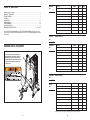
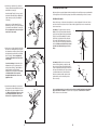
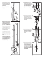
23. Slide the Barbell Adapter (59) onto the Weight
Bar (55). Thread a 1/4” x 9.5mm Allen Head Set
Screw (120) into the Barbell Adapter. Do not
tighten the Screw yet.
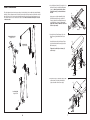
40. Locate the Low Cable (82). Route the eyelet
end of the Cable through the Center Upright (37)
and under a 90mm Pulley (90). Attach the Pulley
inside the Upright with an M10 x 75mm Bolt
(127), two M10 Washers (99), two 17mm Spacers
(86), and an M10 Nylon Locknut (97).
23
Repeat this step with the other Barbell
Adapter (not shown).
55
40
37
97 99
86
90
59
86
82
120
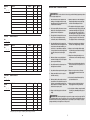
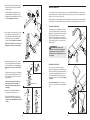
41. Route the Low Cable (82) over a 90mm Pulley
(90) as shown. Attach the Pulley and two Half
Finger Guards (133) to the Double “U”-bracket
(73) with an M10 x 47mm Bolt (136) and an M10
Nylon Locknut (97).
24. Attach the Center Upright (37) to the Center Base
(32) and Rear Base (33) with an M10 x 78mm
Bolt (110), an M10 Washer (99), and an M10
Nylon Locknut (97). Do not tighten the Locknut
yet.
24
99
127
41
97
73
133
Hexagonal
Holes
90
133
136
82
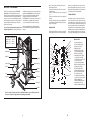
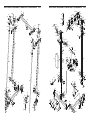
Attach the Center Upright (37) to the Center Base
(32) with an M10 x 75mm Bolt (127), two M10
Washers (99), and an M10 Nylon Locknut (97).
Do not tighten the Locknut yet.
Attach a Weight Carriage Stop (70) to the Rear
Upright (38), at the indicated hole, with an M10 x
88mm Bolt (114) and an M10 Nylon Locknut (97).
Make sure the Square Carriage Bushing (61)
is on top.
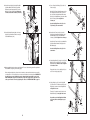
42. Route the Low Cable (82) under a 90mm Pulley
(90) as shown. Attach the Pulley and two Half
Finger Guards (133) to the Rear Base (33) with
an M10 x 47mm Bolt (136) and an M10 Nylon
Locknut (97).
38
Attach the Rear Upright (38), with the hexagonal
holes on the indicated side, to the Rear Base (33)
with two M10 x 75mm Bolts (127), four M10
Washers (99), and two M10 Nylon Locknuts (97).
Do not tighten the Locknuts yet.
42
37
99
97
97
99
97
32
12
33
133
136
Hole
99
127
110
82
90
133
97
99
97
127
61
70
33
114
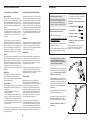
43. Route the Low Cable (82) over a 90mm Pulley
(90) as shown. Attach the Pulley, a Small Cable
Trap (125), and two Half Finger Guards (133) to
the second set of holes from the bottom of the
two Pulley Plates (72) with an M10 x 47mm Bolt
(136) and an M10 Nylon Locknut (97). Make sure
the Cable Trap is oriented to hold the Cable in
the groove of the Pulley.
43
97
133
90
72
133
136
125
82
17