1
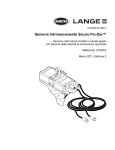
Catalog Number 4979-18
Sigma 911 Flow Meter
Intrinsically Safe (ATEX)
USER MANUAL
August 2009, Edition 6
© Hach Company, 2009. All rights reserved. Printed in the U.S.A.
Table of Contents
Section 1 Safety Precautions .................................................................................................5
1.1
1.2
1.3
1.4
Use of Hazard Information .......................................................................................................... 5
Precautionary Labels .................................................................................................................. 5
Hazardous Locations .................................................................................................................. 6
Intrinsically Safe Equipment ........................................................................................................ 6
1.4.1 Intrinsically Safe Installation Requirements ....................................................................... 7
1.4.2 Intrinsically Safe Wiring Practices ...................................................................................... 8
1.5 Confined Space Entry ................................................................................................................. 9
Section 2 Specifications .......................................................................................................11
Section 3 Getting Started .....................................................................................................13
3.1 Flow Meter Installation Considerations ..................................................................................... 13
3.1.1 Choosing the Proper Site ................................................................................................. 13
3.1.2 Dealing with Difficult Sites ................................................................................................ 13
3.2 Software and Communications ................................................................................................. 13
3.2.1 Required Software ........................................................................................................... 13
Section 4 Meter Installation ..................................................................................................15
4.2 Approved Sigma 911 Installation Drawings .............................................................................. 16
4.3 Installing the Batteries ............................................................................................................... 20
4.3.1 Installing the Battery Pack in the 911 ............................................................................... 20
4.3.2 Battery Compartment Desiccant ...................................................................................... 21
4.3.3 Battery Life Estimates ...................................................................................................... 22
4.4 RS232 Interface Wiring ............................................................................................................. 22
4.4.1 RS232 Serial Port ............................................................................................................ 22
4.5 Installing the Sensor ................................................................................................................. 23
4.5.1 Zeroing the Sensor .......................................................................................................... 24
4.5.2 Important Guidelines for Sensor Installation .................................................................... 25
4.5.3 Connecting the Sensor to the Mounting Bands ............................................................... 26
4.5.4 Placing the Sensor and the Mounting Band into the Pipe ................................................ 27
4.6 Compensating for Velocity Direction ......................................................................................... 28
4.7 Adjusting the Level of the Sensor ............................................................................................. 28
Section 5 Maintenance ..........................................................................................................31
5.1 Maintaining the Battery Compartment Desiccant ..................................................................... 31
5.1.1 Replacing the Battery Compartment Desiccant ............................................................... 31
5.2 Maintaining the O-Ring Gasket on the End Cap ....................................................................... 31
5.3 Cleaning the Flow Meter ........................................................................................................... 31
5.4 Storing the Flow Meter .............................................................................................................. 32
5.5 Cleaning the Connectors .......................................................................................................... 32
5.6 Replacing the Batteries in the RS232 Interface ........................................................................ 33
5.7 Maintaining the Sensor ............................................................................................................. 33
5.7.1 Cleaning the Transducer Port .......................................................................................... 33
5.7.2 Cleaning the Sensor (Oil-filled and Non-oil) ..................................................................... 33
5.7.3 Replenishing the Oil ......................................................................................................... 35
5.8 Changing the Sensor Desiccant ............................................................................................... 38
5.8.1 Replacing the Desiccant .................................................................................................. 38
5.9 Replacing the Hydrophobic Filter .............................................................................................. 39
Section 6 Replacement Parts and Accessories .................................................................41
6.1 Accessories ............................................................................................................................... 41
3
Table of Contents
6.2
6.3
6.4
6.5
Submerged Area/Velocity Sensors ...........................................................................................42
Sensor Mounting Hardware .......................................................................................................43
Mounting Plate Hardware for Directly Mounting to Pipe Wall ....................................................43
Replacement Battery .................................................................................................................43
Section 7 Contact Information for U.S.A. and Outside Europe .........................................45
Section 8 Contact information for Europe ..........................................................................47
Section 9 Warranty ................................................................................................................48
Appendix A Batteries and Chargers ....................................................................................49
4
Section 1
Safety Precautions
Read this entire manual before unpacking, setting up, or operating
this instrument.
Pay particular attention to all danger and caution statements.
Failure to do so could result in serious injury to the operator
or damage to the equipment.
Do not use or install this equipment in any manner other than what
is specified in this manual.
1.1 Use of Hazard Information
If multiple hazards exist, this manual will use the signal word
(Danger, Caution, Important Note, Note) corresponding to the
greatest hazard.
DANGER: Indicates a potentially or imminently hazardous situation
which could result in death or serious injury.
CAUTION: Indicates a potentially hazardous situation that may
result in minor or moderate injury.
Important Note: Information that requires special emphasis.
Note: Information that supplements points in the main text.
1.2 Precautionary Labels
Read all labels and tags attached to the instrument. Personal injury
or instrument damage could occur if not observed.
This symbol, if noted on the instrument, references the instruction manual for operation and/or safety information.
Electrical equipment marked with this symbol may not be disposed of in European public disposal systems after 12
August of 2005. In conformity with European local and national regulations (EU Directive 2002/96/EC), European
electrical equipment users must now return old or end-of life equipment to the Producer for disposal at no charge to
the user.
Note: For return for recycling, please contact the equipment producer or supplier for instructions on how to return
end-of-life equipment, producer-supplied electrical accessories, and all auxiliary items for proper disposal.
This symbol, if noted on an instrument enclosure or barrier, indicates that a risk of electrical shock and/or
electrocution exists. It also indicates that only individuals qualified to work with hazardous voltages should open the
enclosure or remove the barrier.
This symbol, if noted on the instrument, identifies the location of a fuse or a current limiting device.
This symbol, if noted on the instrument, indicates that the marked item can be hot and should not be touched
without care.
This symbol, if noted on the instrument, indicates the presence of devices sensitive to Electro-static Discharge and
indicates that care must be taken to prevent damage to them.
This symbol, if noted on the instrument, identifies a risk of chemical harm and indicates that only individuals
qualified and trained to work with chemicals should handle the chemicals or perform maintenance on the chemical
delivery systems associated with the equipment.
This symbol, if noted on the instrument, indicates the need for protective eye wear.
This symbol, if noted on the instrument, identifies the location of the connection for Protective Earth (ground).
5
Safety Precautions
1.3 Hazardous Locations
DANGER
Although some Sigma products are designed and certified for
installation in hazardous locations as defined by the National
Electrical Code, many Sigma products are not suitable for use
in hazardous locations. It is the responsibility of the
individuals who are installing the products in hazardous
locations to determine the acceptability of the product for the
environment. Additionally, to ensure safety, the installation of
the instrument in hazardous locations must be in accordance
with the manufacturer's control drawing specifications. Any
modification to the instrumentation or the installation is not
recommended and may result in life threatening injury and/or
damage to the facilities.
DANGER
Bien que certains produits Sigma soient conçus et certifiés
pour être installés dans des endroits dangereux tels que
définis par le National Electric Code, de nombreux produits
Sigma ne conviennent pas pour de tels endroits. Il relève de la
responsabilité des personnes qui placent les produits dans
des endroits dangereux de déterminer s'ils sont adaptés à cet
environnement. En outre, à des fins de sécurité, le placement
de machines dans des endroits dangereux doit s'effectuer
dans le respect des consignes des schémas de contrôle du
fabricant. Toute modification apportée aux machines ou tout
déplacement de celles-ci est déconseillé, car susceptible de
provoquer des accidents matériels et/ou corporels.
1.4 Intrinsically Safe Equipment
The 911 Flow Meter is marked as
II2G Ex eq ia IIB T3 for Zone
1 hazardous locations containing explosive gases. The following is
an explanation of this marking:
= Explosion Protection Marking
II = Equipment Group classification for applications other
than mines
2 = Category classification for Zone 1
G = Type of Explosive Atmosphere is gases
Ex = Explosion Protected
e = Protection Method of Increased Safety
q = Protection Method of Powder Filled
ia = Intrinsically Safe Output
IIB = Gas group for Ethylene
T3 = Temperature Class for 200 °C maximum surface temperature
The flow meter is not “Explosion Proof”. If proper safety precautions
are not followed, or if the equipment is not installed properly, there
is a severe possibility of explosion. Be sure to review all safety
precautions, installation, and wiring practices throughout this
manual prior to installing a Sigma 911 Flow Meter.
6
Safety Precautions
1.4.1 Intrinsically Safe Installation Requirements
•
It is important that the installer of an Intrinsically Safe system
reference the requirements of the authority having jurisdiction
at the installation site. The Sigma 911 Flow Meter should be
installed in accordance to these requirements and in
accordance with the approved control drawings in the manual
(Refer to Approved Sigma 911 Installation Drawings on
page 16).
7
Safety Precautions
•
Wherever possible, associated apparatus should be mounted
in a non-hazardous location, closest to the hazardous location.
This will minimize the length of the Intrinsically Safe conductors
within the non-hazardous location, thereby decreasing the
possibility of inadvertent connection to non-intrinsically safe
energy to the protected circuit. It is recommended that the
associated apparatus be mounted and installed in dust and
moisture free enclosures. Dust and moisture are conductive
materials and may reduce the required minimum distance of 50
mm (2 in.) between Intrinsically Safe and Non-Intrinsically Safe
conductors. The panel layout of these enclosures should be
constructed in such a way that the separation of Intrinsically
Safe and Non-Intrinsically Safe conductors is maximized.
WARNING: EXPLOSION HAZARD
Installation of equipment into hazardous locations must be
done so that no friction can be generated between the Flow
Meter and any surrounding surfaces.
1.4.2 Intrinsically Safe Wiring Practices
DANGER
Intinsically Safe wiring must be seperated from
non-intrinsically safe wiring to prevent the transferring of
unsafe levels of energyto the hazardous area.
DANGER
Le câblage à sécurité intrinsèque doit être séparé du câblage à
sécurité non intrinsèque afin d'empêcher tout transfert de
niveaux d'énergie non sûrs vers la zone dangereuse.
The following practices are meant to be used as guidelines or
recommendations only. For specific rules or more detailed
practices, refer to the National Electric Code, Canadian Electric
Code, or ANSI/ISA-RP 12.6-1987 or subsequent.
Intrinsically safe wiring must be installed, maintained, and repaired
with consideration of the following:
Connections
Do not connect non-intrinsically safe wiring to intrinsically safe
terminations of any associated apparatus, usually identified with
light blue.
Routing
Intrinsically safe wiring must enter or leave the non-hazardous
location by the shortest and most direct route.
Clearances
A clearance distance of at least 50 mm (2 in.) must be maintained
between any non-intrinsically safe conductors and any intrinsically
safe wiring or terminations.
The only exceptions allowed for minimum clearances are:
•
8
All intrinsically safe circuit conductors are in Type MI or MC
cables or
Safety Precautions
•
All non-intrinsically safe circuit conductors are in raceways or
Type MI or MC cables where the sheathing or cladding is
capable of carrying fault current to ground.
Raceways
Raceways should be used to keep intrinsically safe wire and
non-intrinsically safe wire separated. Wire lacing or ties are
considered acceptable methods. All raceways for the intrinsically
safe system are identified with permanently affixed labels with the
wording Intrinsic Safety Wiring or equivalent.
Conductor Identification
Intrinsically safe conductors must be identified, either by color
coding with light blue jacketed cable or by tagging, at regular
intervals of every 7.62 m (25 ft), as identified by the NEC.
Voltage Limitations
Non-hazardous location electrical equipment must not contain a
source voltage greater than 250 V unless sufficient means have
been employed to prevent the shorting of a source voltage greater
than 250 V onto the non-intrinsically safe terminals of the
associated apparatus.
Multi-Conductor Cable
Conductors may be part of a multi-conductor cable provided that all
conductors within the cable are intrinsically safe. Each intrinsically
safe conductor must have an insulation thickness of 0.25 mm
(0.010 in.) which is rated for the maximum temperature rating of the
approved device to which it is connected. The intrinsically safe
wiring must be color coded with light blue, if no other wiring is light
blue or appropriately tagged.
Seals
A seal must be provided at the point the intrinsically safe wire
passes between the hazardous and non-hazardous locations to
prevent the hazardous atmosphere from entering the unprotected
control room environment. The seal specification is that it must not
pass more than 198 cu cm (0.007 ft3) of air per hour at a pressure
equivalent to 6 in. (1493 Pascals) of water. While this is the same
specification for the sealing requirements of an explosion proof
system, it may not be necessary to employ those seals.
Grounding
The Sigma 911 Flow Meter and associated Opto-Isolated Interfaces
do not require grounding or bonding. Under no circumstances
should any attempt be made to ground or bond the Sigma 911 or
Opto-Isolated Interfaces.
1.5 Confined Space Entry
Important Note: The following information is provided to guide
users of the Sigma 911 Flow Meter on the dangers and risks
associated with entry into confined spaces.
DANGER
Additional training in Pre-Entry Testing, Ventilation, Entry
Procedures, Evacuation/Rescue Procedures and Safety Work
Practices is necessary to ensure against the loss of life in
9
Safety Precautions
confined spaces.
DANGER
Pour éviter les accidents mortels dans les espaces confinés, il
faut organiser des formations supplémentaires dans les
matières suivantes: Contrôle avant entrée, Ventilation,
Procédures d'entrée, Procédures d'évacuation et de secours
et Méthodes de travail sûres.
On April 15, 1993, OSHA's final ruling on CFR 1910.146, Permit
Required Confined Spaces, became law. This standard directly
affects more than 250,000 industrial sites in the United States and
was created to protect the health and safety of workers in
confined spaces.
Definition of Confined Space
A Confined Space is any location or enclosure that presents or has
the immediate potential to present one or more of the following
conditions:
•
An atmosphere with less than 19.5% or greater than 23.5%
oxygen and/or more than 10 ppm Hydrogen Sulfide (H2S)
•
An atmosphere that may be flammable or explosive due to
gases, vapors, mists, dusts, or fibers
•
Toxic materials which upon contact or inhalation could result in
injury, impairment of health, or death
Confined spaces are not designed for human occupancy. They
have restricted entry and contain known or potential hazards.
Examples of confined spaces include manholes, stacks, pipes,
vats, switch vaults, and other similar locations.
Standard safety procedures must always be followed prior to entry
into confined spaces and/or locations where hazardous gases,
vapors, mists, dusts, or fibers may be present.
Before entering any confined space, check with your employer for
procedures related to confined space entry.
10
Section 2
Specifications
Specifications are subject to change without notice.
General
Certification
II2G Ex eq ia IIB T3 for Zone 1 hazardous locations containing explosive gases
Dimensions
16.5 cm dia. x 57 cm L (6.5 in. x 22.5 in.) with 12 amp battery
Weight
8 kg (17.5 lb) with 12 amp hour battery pack
Enclosure Material
PVC
Enclosure Rating
NEMA, 6P (IP67)
Operating Temp.
–18 to 60°C (0 to 140°F)
Storage Temp.
–40 to 60°C (–40 to 140°F)
Power Source
12 amp hour battery pack
Battery Life
65 days (12 amp hour) typical with a 15 minute recording interval. Assumes data download
once per week, at 10°C (50°F), also affected by site conditions. 21 days (12 amp hour)
typical with a 2 minute recording interval and two total downloads.
User Interface
Optically Isolated Interface to IBM compatible PC
Monitoring Intervals
1, 2, 3, 5, 6, 10, 12, 15, 20, 30, and 60 minutes
Program Memory
Non-volatile, programmable flash, can be updated via RS232 port
Time Based Accuracy
±1 second per day
Level: in., m, cm, ft
Unit Measurements
Flow: gps, gpm, lps, lpm, lph, mgd, afd, cfs, cfm, cfh, cfd, m3s, m3m, m3h, m3d
Totalized Flow: gal, ft3, acre-ft, L, m3
Data Storage
Capacity: 90 days of 1 level reading and 1 velocity reading at a 15 minute recording interval.
Data Types: Level and Velocity, Storage Mode: Wrap or Slate
Communications
Serial connection via optically isolated interface to IBM compatible computer with analysis
software
Velocity Measurement
Method
Doppler Ultrasound Twin 1 MHz piezoelectric crystals
Accuracy(static)
± 2% of reading1
Depth Range
Standard: 0 to 3 m (0 to 0 ft)
Extended: 0 to 9 m (0 to 30 ft)
Recommended Range
–1.52 to 6.10 m/s (–5 to 20 ft/s)
Typical Minimum Depth
2 cm (0.8 in.)
Zero Stability
<0.015 m/s (<0.05 ft/s)
Depth Measurement
Method
Doppler Ultrasound Twin 1 MHz piezoelectric crystals
Accuracy
±0.16% full scale ±1.5% of reading at constant temp (± 2.5°C)
±0.20% full scale ±1.75% of reading from 0 to 30°C (32 to 86°F)
±0.25% full scale ±2.1% of reading from 0 to 70°C (32 to 158°F)
Depth Range
Standard: 0 to 3 m (0 to 10 ft)
Extended: 0 to 9 m (0 to 30 ft)
Maximum Allowable Depth
Standard: 10.5 m (34.5 ft)
Extended: 0 to 9 m (0 to 30 ft)
11
Specifications
Velocity-induced Depth
Error
Compensated based on pipe geometry and flow velocity
Air Intake
Atmospheric pressure reference is desiccant protected.
General
Depth Compensated
Temperature
0 to 70°C (32 to 158°F)
Material
Noryl® plastic outer shell with epoxy potting within
Power Consumption
≤1.2 W @ 12 VDC
Cable
Material: Urethane cable with air vent
Standard Length: 9, 15, 23 and 30.5 m (30, 50, 75 and 100 ft.)
Custom Length: 30.75 to 76 m (101 to 250 ft.) maximum
Diameter: 0.91 cm (0.36 in.)
Dimensions
2.3 cm H x 3.8 cm W x 13.5 cm L (0.9 in. H x 1.5 in. W x 5.31 in. L)
Operating Temperature
Range
0 to 70°C (32 to 158°F)
1 For
12
temperatures above 40 °C (104 °F) add ± 0.3 cm/°C (0.03 in./°F)
Section 3
Getting Started
3.1 Flow Meter Installation Considerations
3.1.1 Choosing the Proper Site
The accuracy of flow measurement depends on the suitability of
individual monitoring sites. Select sites that have normalized flow
and minimal turbulence. Turbulence can make it difficult to detect
an average velocity in the flow stream. Obstructions, vertical drops,
pipe bends, and elbows can create turbulence. Table 1 contains
suggestions for preventing turbulence.
Table 1 Suggestions for Preventing Turbulence
Site Condition
Suggested Remedy
Outfalls
Attach the sensor at least ten times the maximum expected level upstream of the outfall.
Vertical drops in the
channel floor
Attach the sensor at least ten times the maximum expected level upstream of the vertical drop.
Elbows, sharp turns, and
“Y” connections
Attach the sensor at least ten times the maximum expected level upstream of the obstruction.
Attach the sensor at least ten times the maximum expected level downstream of the vertical drop.
Attach the sensor at least ten times the maximum expected level downstream of the obstruction.
3.1.2 Dealing with Difficult Sites
Some sites may be difficult to monitor due to poor site conditions.
The direction and speed of particles in the flow stream contribute to
the signal received by the velocity sensor. If turbulence near the
measurement point is excessive, it may be difficult for the sensor to
determine the average velocity of the stream. The flow meters
provide several unique features to help deal with these
problem sites.
3.2 Software and Communications
3.2.1 Required Software
Programming and data retrieval are performed via an IBM
compatible personal computer (computer must have a serial port,
USB is not supported) using an Optically Isolated Interface with
Hach’s Data Analysis Software.
The Sigma 911 uses built-in flow equations for analysis.
13
Getting Started
14
Section 4
Meter Installation
DANGER
Some of the following manual sections contain information in
the form of warnings, cautions, important notes and notes that
require special attention. Read and follow these instructions
carefully to avoid personal injury and damage to the
instrument. Only personnel qualified to do so should conduct
the maintenance tasks described in this portion of the manual.
WARNING: EXPLOSION HAZARD
Installation of equipment into hazardous locations must be
done so that no friction can be generated between the Flow
Meter and any surrounding surfaces (Figure 1).
Figure 1 Flow Meter friction clearance
This section describes the ONLY approved installation instructions
for the Sigma 911 Flow Meter. This section also describes battery
installation and interface wiring for RS232, Modem, and Sampler
connection.
4.1 Mounting the flow meter
When mounting the flow meter, remember to:
•
Mount the meter so that the connectors face down. The end
of the meter that contains the batteries should face up. If the
connectors face up, they may corrode and allow water to seep
into the instrument. Refer to Figure 2 on page 16.
•
When not in use, cover the connectors with their protective
caps to prevent corrosion.
Use the appropriate manhole support bracket/spanner bar. See
Replacement Parts and Accessories on page 41.
15
Meter Installation
Figure 2 Installation options
1
Instrument Support Bracket (Cat. No. 5713000)
4
911 flow meter
2
Manhole cover
5
Wall/Ladder Mount Suspension Bracket (Cat. No. 4874
and Cat. No. 4839)
3
Suspension harness (Cat. No. 4920)
6
940 flow meter
4.2 Approved Sigma 911 Installation Drawings
DANGER
Any installation or flow meter configuration that is not
specifically detailed on the following control drawings is not
allowed. In all cases, the local authority having jurisdiction
shall have the final say.
DANGER
Il est interdit de procéder à toute installation ou configuration
d'un débitmètre qui n'est pas explicitement détaillée dans les
schémas de contrôle de l'installation ci-dessous. Dans tous
les cas, c'est l'autorité locale responsable qui aura le dernier
16
Meter Installation
mot.
Figure 3 on page 18 and Figure 4 on page 19 are approved control
drawings. These certified drawings explain the ONLY approved
method of installing the Sigma 911 Flow Meter. Additionally, these
drawings list both part number, description, and the only certified
sensors, probes, and associated equipment to be used with these
meters. Any substitutions will automatically void the Intrinsically
Safe certification of the flow meter and could result in fire or
explosion.
17
Meter Installation
Figure 3 Installation Control Drawing 1
18
Meter Installation
Figure 4 Installation Control Drawing 2
19
Meter Installation
4.3 Installing the Batteries
DANGER
Use only exact replacement battery packs purchased directly
from the factory or a factory authorized outlet. Any
unauthorized battery substitution will void the intrinsically
safe design and approval of the unit and could result in a fire
or explosion.
DANGER
Utilisez exclusivement des batteries de rechange identiques
que vous achetez directement auprès de l'usine ou d'un point
de vente agréé par celle-ci. Tout remplacement non autorisé
d'une batterie annule la conception à sécurité intrinsèque et
l'agréation de l'appareil, et peut provoquer un incendie ou une
explosion.
Never short circuit, puncture, deform, or incinerate any of the
battery packs used in the Sigma 911. Proper precautions must be
observed in the handling, shipping, and disposal of battery packs.
4.3.1 Installing the Battery Pack in the 911
DANGER
Lead acid batteries may release explosive gases during
charging. Allow at least 30 minutes for gases to dissipate
before deployment. Battery must be upright in order for gases
to vent.
DANGER
Never install, remove or charge batteries in a hazardous
location.
DANGER
Vous ne devez jamais installer, retirer ou recharger les
batteries dans un environnement dangereux.
The entire battery assembly unscrews and separates to access the
battery connector (Cat. No. 5160-01).
1. Hold the Sigma 911 by the handle on the end and twist
counter-clockwise to open.
2. Remove the rechargable battery pack. Recharge or dispose
off the battery.
DANGER
Batteries have a finite service life. Some battery failure modes
may present a fire or explosion hazard. Before deploying any
battery, measure its voltage and conductance with an IEEE
1188 compliant tester (Midtronics DM-3200 or similar). Do not
deploy batteries with voltages below 11.5 V. Do not deploy
batteries whose measured conductance is not within 20% of
nominal (new) value.
3. Reinstall the rechargable battery. Attach the battery connector
to the center mounted connector at the bottom of the 911 case
20
Meter Installation
(Figure 5 on page 21). Both connectors are physically
polarized.
4. Place the two connectors together. Gently try to pull the two
connectors apart to ensure that the connectors are securely
latched together. Do not use excessive force, or permanent
damage to the connectors may occur.
5. Screw the battery pack assembly onto the flow meter
1
2
Figure 5 Sigma 911 Flow Meter Case and Battery Packs
1
Sigma 911 Case
2
12 amp-hour rechargeable gel-cell battery pack
4.3.2 Battery Compartment Desiccant
The battery compartment in the Sigma 911 is kept dry with a small
desiccant cartridge to avoid moisture damage to the batteries and
power circuitry (Figure 6). When the beads are blue they can
remove moisture from the enclosure. When they turn pink, they
cannot absorb any more moisture. When the blue desiccant turns
pink, replace the desiccant.
Figure 6 Sigma 911 Case, Battery End with Inserted Desiccant
1
Dessicant
21
Meter Installation
4.3.3 Battery Life Estimates
When using the battery pack, battery life is based on:
•
Recording intervals (longer intervals increase battery life).
•
Temperature (colder temperatures decrease battery life).
•
Site hydraulics (second order effect caused by excessive
turbulence).
•
Interval between downloads.
The typical expected battery life for Sigma 911 is 90 days with the
12 amp-hour gel cell (Cat. No. 62370000) under the following
conditions:
•
15 minute logging intervals
•
1 level channel and 1 velocity channel logged
•
Data downloaded once per week
•
10°C (50°F) ambient temperature
•
Also affected by site conditions
4.4 RS232 Interface Wiring
DANGER
All connections to the flow meter must be made in a
non-hazardous location.
DANGER
Tous les raccordements au débitmètre doivent être effectués
dans un environnement qui ne présente aucun danger.
All RS232 interface wiring must follow the installation drawings in
section 4.2 on page 16.
4.4.1 RS232 Serial Port
DANGER
The RS232 Opto-Isolated Interface must be located in a
non-hazardous location.
DANGER
L'interface à isolation optique RS232 doit se trouver en un
emplacement non dangereux, conformément aux schémas de
contrôle de l'installation.
Important Note: The PC or laptop must be used in a
non-hazardous location.
The high speed RS232 serial port communicates with a PC via an
optically isolated interface. The Opto-Isolated Interface (Cat. No.
4087) is only used for data downloading and remote programming.
This interface isolates the energy potential in the PC from
hazardous locations and from the Sigma 911.
DANGER
Route the cable through an approved seal to prevent migration
22
Meter Installation
of dangerous fumes or vapors from the hazardous location to
the non-hazardous location.
DANGER
Acheminez le câble à travers un joint approuvé afin
d'empêcher la migration de fumées ou vapeurs dangereuses
de l'emplacement dangereux vers l'emplacement non
dangereux.
1. Attach the cable with the round connector from the
Opto-Isolated Interface to the connector on the Sigma 911
labelled RS232.
2. Attach the cable with a rectangular connector to the appropriate
serial COM port on the PC or laptop.
1
2
3
4
Figure 7 RS232 Communications Setup
1
Use “approved” seal to minimize passage of gases or vapors from hazardous location to non-hazardous location.
2
RS232, Opto-isolated interface in non-hazardous location (Cat. No. 4087).
3
PC compatible laptop or desktop located in non-hazardous location for downloading data.
4
Sigma 911 Flow Meter in hazardous location.
4.5 Installing the Sensor
Read the instructions carefully before installing the sensor. Failure
to do so could result in serious injury to the operator or damage to
the equipment.
23
Meter Installation
4.5.1 Zeroing the Sensor
The sensor has been factory-calibrated and compensated for
temperature. The sensor needs to be zeroed during each
installation, but does not require calibration. The sensor should be
zeroed when moving it from one flow meter or sample to another.
For specific zeroing instructions, refer to the appropriate flow meter
or sampler manual.
24
Meter Installation
4.5.2 Important Guidelines for Sensor Installation
•
Do not install more than one sensor at a time in pipes less than
61 cm (24 inches). Multiple sensors in smaller pipes can create
turbulent or accelerated flows near the sensors that may cause
inaccurate measurements.
•
Mount the sensor as close as possible to the bottom of the pipe
invert to accurately measure low velocity levels.
•
Do not monitor flows in the invert of the manhole itself. The best
sensor location is 3 to 5 times the sewer diameter/height
upstream of the invert.
•
Locate monitoring sites as far as possible from inflow junctions
to avoid interference caused by combined flows.
•
Avoid sites that contain flow obstacles within 2 to 4 pipe
diameters in front of the sensor installation (rocks, stones, pipe
joints, valve stems, etc.) as these will contribute to turbulence
and generate high speed flows in the immediate vicinity of the
obstruction.
•
Avoid any sites with slow moving flows that will encourage the
build-up of silt in the invert or channel. Excessive silting around
the sensor may inhibit the Doppler signal and decrease sensor
accuracy, and may affect depth measurement accuracy.
•
Avoid sites with deep, rapid flows that will make it physically
difficult or dangerous to install the sensor.
•
Avoid sites with high velocity, low-depth flows. Splash-over and
excessive turbulence will be present around the sensor and
data may be inaccurate.
4.5.2.1 Proper Strain Relief of Sensor Cable
Attach the desiccant hub to the instrument handle to provide a
strain relief for the sensor cable and connector (Figure 8).
Figure 8 Proper Strain Relief
1
Lanyard
3
Desiccant Hub
2
Carabineer
4
Flow Meter
25
Meter Installation
4.5.3 Connecting the Sensor to the Mounting Bands
Important Note: If using an oil-filled sensor, replenish the oil prior
to mounting the sensor to a mounting band. Refer to 5.7.3 on
page 35 for oil replenishment instructions, if applicable.
1. Attach the sensor to the mounting band. Mounting bands come
with pre-drilled holes for direct mounting of the sensor to
the band.
2. To reduce the likelihood of debris collecting on the cable and
the mounting band, route the cable along the edge of the band
and fasten the cable to the mounting band with nylon wire ties
(Figure 9). The cable should exit the tied area at, or near the
top of the pipe to keep it out of the flow stream.
Note: If there is a large amount of silt at the bottom of the pipe, rotate the
band until the sensor is out of the silt (Figure 10), assuring that the sensor
remains below the minimum expected water level at all times. The silt
should not be disturbed and must be measured frequently.
1
4
2
3
Figure 9 Attaching the Sensor to the Mounting Band
1
Mounting band
3
Screws (2)
2
Sensor
4
Nylon Wire Ties
3
1
4
2
Figure 10 Avoiding Silt when Mounting the Sensor
1
26
Water
2
Silt
3
Pipe
4
Sensor
Meter Installation
4.5.4 Placing the Sensor and the Mounting Band into the Pipe
Point the angle-face of the sensor into the flow. The manufacturer
recommends placing the sensor with the arrow pointing with the
flow (Figure 11). For other mounting configurations, see the
appropriate flow meter manual.
Slide the mounting band as far as possible into the pipe to eliminate
drawdown effects near the end of the pipe. Locate the sensor at the
bottom-most point in the channel. If excessive silt is present on the
bottom of the pipe, rotate the band in the pipe until the sensor is out
of the silt.
Manhole
Velocity Sensor
Normal Upstream Position
Manhole
Velocity Sensor
Downstream Position
Figure 11 Placing the Sensor into the Flow
27
Meter Installation
4.6 Compensating for Velocity Direction
When programming the sensor the following may be selected:
Option1
Upstream
(recommended for
most applications)
Description
Use this option at sites with fairly consistent velocities, and low to medium turbulence. The flow stream
over the sensor should be relatively straight, with no drops or turns near the measurement point.
Mount the sensor in the pipe, beveled edge facing into the flow, where the flow stream enters the
measurement area (Figure 11).
Use this option when the sensor is installed downstream of the measurement point (where the flow
stream exits the site). This option is useful when more than one flow stream enters a site and the
combined flow of all streams at a single exit point is measured.
Downstream
Mount the sensor in the downstream direction rather than the typical upstream direction. Mounting the
sensor 'backwards' in this manner (Figure 11) causes the velocity direction readings to be the
opposite of actual stream flow. By selecting the Downstream choice when programming, the logger
reverses the measured signal to show actual flow direction (beveled edge downstream). The
maximum velocity obtained in this type of installation is 5 fps.
1 Additional options may be available depending on the flow meter or sampler used. Refer to the appropriate flow meter or sampler
manual for more information.
4.7 Adjusting the Level of the Sensor
The manufacturer recommends doing a level adjustment whenever
a sensor is first installed into a flow stream. This adjustment
accounts for the various physical tolerance stack-ups in the system
(i.e., thickness of the mounting band, angular placement of the
sensor relative to the “6 O’ clock” position in the pipe, etc.)
1. With the sensor installed in the flow, be certain that the flow
meter is connected to a PC and that the software displays
Current Status.
2. Take a physical measurement of the water depth by measuring
the distance from the top of the pipe to the surface of the water
(item B, Figure 12), and subtracting this number from the pipe
diameter (item A, Figure 12). The resulting number is the water
depth (item C, Figure 12).
3. Enter the physically-measured water depth into the software
using the Adjust Level function.
B
A
C
Figure 12 Measuring the Water Level
28
Meter Installation
29
Meter Installation
30
Section 5
Maintenance
DANGER
Only qualified personnel should conduct the tasks
described in this section of the manual.
DANGER
Seul un technicien qualifié peut effectuer les tâches
d'installation décrites dans cette section du manuel.
DANGER
All maintenance activities related to flow meter and flow meter
accessories must be performed in a non-hazardous location.
DANGER
Toutes les opérations de maintenance relatives au
débitmètre et à ses accessoires doivent être exécutées
dans un environnement qui ne présente aucun danger.
5.1 Maintaining the Battery Compartment Desiccant
The desiccant material is a silica gel indicator. When the gel is
saturated with moisture, the beads turn from blue to pink. To
recondition the beads for reuse, remove them from the assembly.
Heat the beads in an oven at 100 to 180°C (212 to 350°F) until the
beads turn blue again. Discard and replace the beads if they do not
turn blue after heating.
5.1.1 Replacing the Battery Compartment Desiccant
A small desiccant cartridge in the battery compartment prevents
moisture damage to the batteries and power circuitry (Figure 6 on
page 21).
If the normally blue desiccant beads turn pink, replace the cartridge
or remove the cartridge end cap and recharge or replace the
desiccant material. A small clip holds the desiccant cartridge in
place. Pull the cartridge straight out of the clip to remove it.
5.2 Maintaining the O-Ring Gasket on the End Cap
Note: Do not use petroleum jelly to lubricate the O-rings.
Two O-ring gaskets (Cat. No. 4912) are installed in each flow meter
end cap. The end caps maintain the water tight seal on the flow
meter. Use care when the end caps are removed; do not soil, cut, or
nick the gaskets. Replace them immediately if any physical damage
is apparent. Use a light coating of O-ring lubricant to help maintain
a water-tight seal.
5.3 Cleaning the Flow Meter
WARNING: EXPLOSION HAZARD
To avoid electrostatic discharge, clean only with a wetted
cotton type cloth, or remove from the hazardous zone.
Clean the outside of the logger case with warm water and mild
detergent. Do not use solvents or harsh cleaners to clean the
logger. Do not use high pressure washing equipment to clean
the case.
31
Maintenance
5.4 Storing the Flow Meter
Remove all the batteries from the logger when storing for long
periods (more than 3 months). Store the sensors in a dry area.
Make sure that all the desiccant materials in the probes are kept
fresh (blue) at all times.
5.5 Cleaning the Connectors
Coat the connectors with lithium or di-electric grease to prevent
corrosion.
32
Maintenance
5.6 Replacing the Batteries in the RS232 Interface
DANGER
Never replace batteries in a hazardous location.
DANGER
Ne jamais remplacer les piles dans une zone dangereuse.
The Opto-Isolated RS232 interface uses a quantity of industrial
quality Alkaline “C” cells. Under normal circumstances the batteries
should last for more than 1,000 downloads based on an average
download time of 5 minutes. The batteries need to be changed
once a year due to the limited shelf life of any type of battery.
1. Remove the cover from the RS232 interface.
2. Remove the old batteries. Install fresh batteries into the RS232
interface, making certain the polarity is correct.
Figure 13 Replacing RS232 Batteries
5.7 Maintaining the Sensor
5.7.1 Cleaning the Transducer Port
Clean the transducer port when:
•
You observe drift in the readings.
•
Level data are missing or incorrect but velocity data
are valid.
•
Excessive silt has deposited between the transducer and
its protective cover.
5.7.2 Cleaning the Sensor (Oil-filled and Non-oil)
Important Note: DO NOT interchange an oil-filled protective cover
plate with a non-oil cover plate. This will adversely affect level
readings. It is possible to convert one type of sensor to the other
using the Oil Probe Conversion Kit (Cat. No. 7730000), refer to the
Oil Probe Conversion Kit Instruction Sheet, Cat. No. 7730089 for
more information.
Important Note: When cleaning the transducer, use the most
gentle technique possible. Do not use sharp or pointed object
33
Maintenance
remove sediment from the face of the transducer. If you nick or dent
the transducer, it will break!
1. Soak the sensor in soapy water.
Note: Do not soak the sensor in bleach. Bleach will permanently damage
the sensor. Refer to Table 2 for acceptable cleaning solutions.
Table 2 Cleaning Solutions
Acceptable
Unacceptable
Dish Detergent and Water
Concentrated Bleach
Window Cleaner
Kerosene
Isopropyl Alcohol
Gasoline
Dilute Acids
Aromatic Hydrocarbons
2. Remove the screws from the protective cover (Figure 15 on
page 35).
3. Remove the cover and gasket.
4. Swirl the sensor carefully in an appropriate cleaning solution to
remove soil. Use a spray or squeeze bottle to wash away
heavier deposits.
5. Clean the gasket and the cover. Replace the gasket (Cat. No.
7722000) if it is torn or damaged. Level readings will be
adversely affected if the gasket is damaged or not installed.
6. Reattach the gasket and the cover (note orientation in
Figure 15 on page 35). Tighten the screws until the gasket
starts to compress.
7. If using an oil-filled sensor, continue to Replenishing the Oil on
page 35.
34
Maintenance
1
2
3
4
5
Figure 14 Removing the Protective Cover (Non-Oil Sensor)
1
Sensor
2
Screws (#6–32 x
3
Protective Cover
5/16)
4
Gasket
5
Pressure Transducer
2
1
3
4
5
6
Figure 15 Removing the Protective Cover (Oil-filled Sensor)
1
Sensor
2
Screws (#6–32 x
3
Protective Cover
5/16)
4
Screw, set, #2-56
5
Gasket
6
Pressure Transducer
5.7.3 Replenishing the Oil
The manufacturer recommends inspecting the oil in the sensor for
large air bubbles during the customer-scheduled service duty cycle,
and prior to every installation. Small bubbles (less than ¼-in.
diameter) of air within the oil do not affect performance. Larger
bubbles may minimize the anti-fouling benefit of the oil.
1. Remove the yellow tape on the sensor, if the sensor is new.
2. Remove any debris from the sensor.
35
Maintenance
3. Load the oil cartridge into the dispensing gun (Figure 16).
4. Twist the feed tube onto the cartridge and attach the syringe tip
to the feed tube (Figure 17 on page 37).
5. Press the dispenser gun handle to purge any air bubbles from
the syringe tip.
6. Remove the set screw in the transducer cover with the supplied
0.035 hex wrench. Retain the set screw.
7. Insert the syringe tip slowly into the set screw hole and
dispense the oil (Figure 18 on page 37). While dispensing the
oil, hold the probe at an angle to allow the air to be pushed out
the side port (Figure 18 on page 37). Continue to dispense the
oil until all the air bubbles are removed.
Note: Slowly insert the syringe tip and do not dispense oil during insertion
or damage to the transducer may occur if too much pressure is applied.
36
Maintenance
8. Continue to dispense the oil while removing the syringe from
the set screw hole to prevent air bubbles. Replace the set
screw until it is flush with the transducer cover and remove any
excess oil around the screw hole or on the sensor.
9. Clean the entire probe and place a piece of electrical tape over
the side port to prevent oil from leaking out. Remove the tape
from the sensor prior to zeroing and installing the sensor.
2
1
Figure 16 Loading the Cartridge into the Dispensing Gun
1
Dispensing Gun
2
Silicone Oil Cartridge
Figure 17 Attaching the Feed Tube and Syringe
1
3
2
4
Figure 18 Oil Replenishment
1
Sensor
3
Side port
2
Set screw
4
Syringe
37
Maintenance
5.8 Changing the Sensor Desiccant
The desiccant canister contains beads of silica gel which ensure
proper orientation of the pressure transducer. When the beads are
blue, they can remove moisture from the air. When they are pink,
they are saturated and cannot absorb any more moisture from the
air, and they must be replaced immediately.
Important Note: When the beads begin to turn pink, replace or
recondition the beads. Permanent damage to the sensor may occur
if the desiccant is not maintained. Never operate the sensor without
the proper desiccant. When rejuvenating beads, remove them from
the canister and heat at 100 to 180 °C (212 to 350 °F) until the
beads turn blue. If the beads do not turn blue, replace them with
new beads. Do not heat the canister.
5.8.1 Replacing the Desiccant
Note: Replacing the desiccant does not require that the desiccant
container be removed from the desiccant box.
1. Use a slight twisting motion to twist the bottom end-cap until its
slots align with the retaining clips (Figure 19).
2. Remove the end cap gently by grasping it and pulling it
straight out.
3. Pour the desiccant beads out of the canister.
4. Hold the canister up to the light and inspect the
hydrophobic filter.
•
If you see a small, dim light spot while looking through the
hole, the filter is in good condition. If you see a bright light
spot, the filter is probably torn. Replace the filter.
•
If the desiccant beads are completely saturated with water
or the filter has been saturated with water or grease,
replace the filter.
If you need to replace the filter, complete the Replacing the
Hydrophobic Filter on page 39, then continue with step 5.
5. Refill the canister tube with blue desiccant beads
(Cat. No. 3624). Inspect the O-ring (Cat. No. 5252) on the
bottom cap for cracks, pits, or evidences of leakage. Replace if
necessary.
Note: Applying O-ring grease to new or dry O-rings improves the ease of
insertion, sealing, and life span of the O-ring.
6. Make sure that the O-ring is clean and free of dirt or debris
before replacing the end cap.
7. Reinstall the end cap.
38
Maintenance
Figure 19 Removing the Bottom End Cap
1
End Cap
2
Desiccant Container
5.9 Replacing the Hydrophobic Filter
A single Teflon® hydrophobic filter (Cat. No. 3390) is installed in the
top of the canister to prevent liquid from entering the vent tube.
For best performance and to avoid grease buildup on the filter
during submergence or surcharge conditions, hang the canister
vertically so that the end facing the sensor points downward.
1. Disconnect the tubing from the top of the desiccant canister.
2. Unscrew the hex-head tubing nipple from the top of the canister
and discard the old filter.
3. Discard any remnants of Teflon tape from the nipple’s threads.
Reapply two turns of Teflon tape (Cat. No. 10851-45) to the
threads, pulling the tape into the threads until it conforms to the
shape of the threads.
4. Place a new filter over the hole. Make sure that the smooth side
of the filter faces the inside of the canister (Figure 20).
5. Place the threaded nipple on top of the filter.
6. With a slight pressure, press the filter into the hole with the
nipple threads and begin threading the nipple into the hole. The
filter will deflect upward and feed completely into the thread
until it disappears. The filter must rotate with the nipple as it is
threaded into the cap. If it does not, it is torn. Start over with a
new filter.
7. Inspect the installation. In the upper cap, a small, dim light spot
should be visible when held up to the light. A bright spot
indicates a torn filter. Start over with a new filter.
39
Maintenance
1
2
Figure 20 Replacing the Hydrophobic Filter
1
Filter, smooth side down
2
Hex-head tubing nipple
40
3
Finished assembly
3
Section 6
Replacement Parts and Accessories
6.1 Accessories
Description
Part Number
Silicon oil dual 50ml oil pack only. Refills 100 sensors
7724700
Silicon oil refill kit includes dispensing tool, dual 50ml oil pack, instruction sheet and miscellaneous
hardware. Refills 100 sensors
7724800
Instruction Sheet, Oil Fill Kit
7724789
Instruction Sheet, Firmware Upgrade
7726089
Gel Fill Dispensing Gun (also doubles as silicone oil fill gun)
7715300
Retrofit kit for transforming a sensor with a non-oil cover plate into Oil filled cover plate. Includes kit
77248-00
7730000
RS232 Intrinsically Safe Barrier
4087
Suspension Cable (for hanging flow meter)
4920
Manhole Spanner Bars, 18–27 in.
9542
Manhole Spanner Bars, 28–48 in.
9557
Desiccant Cartridge for Electronics
4936
Desiccant Cartridge for Battery
4967
User Manual
4979
Insertion Tool for Mounting Rings
9574
Manhole Support Bracket; 18-27"
5713000
41
Replacement Parts and Accessories
6.2 Submerged Area/Velocity Sensors
GROUP Intrinsically Safe
Description
Part Number
0-10 ft. Depth
I.S. Oil-Filled Area/
Velocity Sensors
W/Connectors
I.S. Oil-Filled Submerged AV Sensor, 0-10 ft range, 30 ft cable, with connector
88064-030
I.S. Oil-Filled Submerged AV Sensor, 0-10 ft range, 50 ft cable, with connector
88064-050
I.S. Oil-Filled Submerged AV Sensor, 0-10 ft range, 75 ft cable, with connector
88064-075
I.S. Oil-Filled Submerged AV Sensor, 0-10 ft range, 100 ft cable, with connector
88064-100
0-30 ft. Depth
I.S. Oil-Filled Submerged AV Sensor, 0-30 ft range, 30 ft cable, with connector
88074-030
I.S. Oil-Filled Submerged AV Sensor, 0-30 ft range, 50 ft cable, with connector
88074-050
I.S. Oil-Filled Submerged AV Sensor, 0-30 ft range, 75 ft cable, with connector
88074-075
I.S. Oil-Filled Submerged AV Sensor, 0-30 ft range, 100 ft cable, with connector
88074-100
0-10 ft. Depth
I.S. Standard Area/
Velocity Sensors
W/Connectors
I.S. Submerged AV Sensor, 0-10 ft range, 30 ft cable, with connector
88065-030
I.S. Submerged AV Sensor, 0-10 ft range, 50 ft cable, with connector
88065-050
I.S. Submerged AV Sensor, 0-10 ft range, 75 ft cable, with connector
88065-075
I.S. Submerged AV Sensor, 0-10 ft range, 100 ft cable, with connector
88065-100
0-30 ft. Depth
I.S. Submerged AV Sensor, 0-30 ft range, 30 ft cable, with connector
88075-030
I.S. Submerged AV Sensor, 0-30 ft range, 50 ft cable, with connector
88075-050
I.S. Submerged AV Sensor, 0-30 ft range, 75 ft cable, with connector
88075-075
I.S. Submerged AV Sensor, 0-30 ft range, 100 ft cable, with connector
88075-100
0-10 ft. Depth
I.S. Oil-Filled Area/
Velocity Sensors
W/Connectors
I.S. Oil-Filled Submerged AV Sensor, 0-10 ft range, 30 ft cable, with connector
88064-030
I.S. Oil-Filled Submerged AV Sensor, 0-10 ft range, 50 ft cable, with connector
88064-050
I.S. Oil-Filled Submerged AV Sensor, 0-10 ft range, 75 ft cable, with connector
88064-075
I.S. Oil-Filled Submerged AV Sensor, 0-10 ft range, 100 ft cable, with connector
88064-100
0-30 ft. Depth
I.S. Oil-Filled Submerged AV Sensor, 0-30 ft range, 30 ft cable, with connector
88074-030
I.S. Oil-Filled Submerged AV Sensor, 0-30 ft range, 50 ft cable, with connector
88074-050
I.S. Oil-Filled Submerged AV Sensor, 0-30 ft range, 75 ft cable, with connector
88074-075
I.S. Oil-Filled Submerged AV Sensor, 0-30 ft range, 100 ft cable, with connector
88074-100
0-10 ft. Depth
I.S. Standard Area/
Velocity Sensors
W/Connectors
42
I.S. Submerged AV Sensor, 0-10 ft range, 30 ft cable, with connector
88065-030
I.S. Submerged AV Sensor, 0-10 ft range, 50 ft cable, with connector
88065-050
I.S. Submerged AV Sensor, 0-10 ft range, 75 ft cable, with connector
88065-075
I.S. Submerged AV Sensor, 0-10 ft range, 100 ft cable, with connector
88065-100
0-30 ft. Depth
I.S. Submerged AV Sensor, 0-30 ft range, 30 ft cable, with connector
88075-030
I.S. Submerged AV Sensor, 0-30 ft range, 50 ft cable, with connector
88075-050
I.S. Submerged AV Sensor, 0-30 ft range, 75 ft cable, with connector
88075-075
I.S. Submerged AV Sensor, 0-30 ft range, 100 ft cable, with connector
88075-100
Replacement Parts and Accessories
6.3 Sensor Mounting Hardware
Option
Submerged Area/Velocity Mounting
Rings for 6–24 in. Pipes
Submerged Area/Velocity Mounting
Bands for 15–42 in. Pipes
Pipe Diameter (Inches)
Part Number (Mounting Ring/Band)
6
1361
8
1362
10
1363
12
1364
15
1365
18
1366
20-21
1353
24
1370
15
9706100
18
9706200
21
9706300
24
9706400
27
9706500
30
9706600
33
9706700
36
9706800
42
9706900
15-42
3766
6.4 Mounting Plate Hardware for Directly Mounting to Pipe Wall
Sensor Type
Submerged Pressure
Part Number
4939
6.5 Replacement Battery
Item
Battery for ATEX certified 911 Flow Meter
Part Number
6237000
43
Replacement Parts and Accessories
44
Section 7
Contact Information for U.S.A. and Outside
Europe
Ordering Information for the U.S.A.
By Telephone:
(800) 368-2723
By Fax:
301-874-8459
By Mail:
Hach Company
4539 Metropolitan Court
Frederick, MD 21704-9452, U.S.A
Ordering information by E-mail:
[email protected]
Information Required
•
Hach account number (if available) •
Billing address
•
Your name and phone number
•
Shipping address
•
Purchase order number
•
Catalog number
•
Brief description or model number
•
Quantity
Ordering Information for Outside the U.S.A. and Europe
Hach maintains a worldwide network of dealers and distributors. To locate the
representative nearest you, send an e-mail to: [email protected] or visit
ww.hachflow.com.
Technical Support
Technical and Customer Service Department personnel are eager to answer questions
about our products and their use. In the U.S.A., call 1-800-635-1230. Outside the U.S.A.
and Europe, send E-mail to [email protected] or call 1-301-874-5599.
Repair Service
Authorization must be obtained from Hach Company before sending any items for repair.
To send the monitor to the factory for repair:
1. Identify the serial number of the monitor unit.
2. Record the reason for return.
3. Call the Customer Service Department (1-800-368-2723) and get a Service Request
Number (SRN) and shipping label.
4. Use the shipping label provided and ship the equipment in the original packaging if
possible.
Note: Do not ship manuals, computer cables, or other parts with the unit unless they are required for
repair.
5. Make sure the equipment is free from foreign debris and is clean and dry before
shipping. Sensors returned without cleaning will be charged a fee.
6. Write the SRN number on the shipping box.
45
7. Make sure that all return shipments are insured.
8. Address all shipments to:
Hach Company
5600 Lindbergh Drive - North Dock
Loveland, Colorado, 80539-0389 U.S.A.
Attn: SRN#XXX
46
Section 8
Contact information for Europe
For technical support, repair service and ordering information please refer to the contact
information below.
For all countries except France, Spain and Great Britain:
Flow-Tronic
RUE J.H. COOL 19a
B-4840 Welkenraedt
Belgium
Ph: +32-87-899797 or 899799
Fx: +32-87-899790
Email: [email protected]
www.flow-tronic.com
For France, Spain and Great Britain:
France
HACH LANGE FRANCE S.A.S.
33, Rue du Ballon
93165 Noisy-le-Grand
Telephone: ++33 (0)1 48 15 68 70
Fax.: ++33 (0)1 48 15 80 00
E-mail: [email protected]
www.hach-lange.fr
Spain
HACH LANGE, S.L.U
C/ Larrauri, 1C, 2ª Pl.
48160 Derio, Bizkaia
Telephone: 902 131441 94 6573388
Fax: 94 6573397
E-mail: [email protected]
www.hach-lange.es
Great Britain:
HACH LANGE LTD
Pacific Way
Salford
Manchester M50 1DL
Telephone: 0 161 872 1487
Fax.: 0 161 872 7324
Email: [email protected]
www.hach-lange.co.uk
47
Section 9
Warranty
Hach Company warrants this product to the original purchaser against any defects that are due
to faulty material or workmanship for a period of one year from date of shipment.
In the event that a defect is discovered during the warranty period, Hach Company agrees that, at
its option, it will repair or replace the defective product or refund the purchase price, excluding
original shipping and handling charges. Any product repaired or replaced under this warranty
will be warranted only for the remainder of the original product warranty period.
This warranty does not apply to consumable products such as chemical reagents; or
consumable components of a product, such as, but not limited to, lamps and tubing.
Contact Hach Company or your distributor to initiate warranty support. Products may not be
returned without authorization from Hach Company.
Limitations
This warranty does not cover:
•
Damage caused by acts of God, natural disaster, labor unrest, acts of war (declared or
undeclared), terrorism, civil strife or acts of any governmental jurisdiction
•
Damage caused by misuse, neglect, accident or improper application or installation
•
Damage caused by any repair or attempted repair not authorized by Hach Company
•
Any product not used in accordance with the instructions furnished by Hach Company
•
Freight charges to return merchandise to Hach Company
•
Freight charges on expedited or express shipment of warranted parts or product
•
Travel fees associated with on-site warranty repair
This warranty contains the sole express warranty made by Hach Company in connection with its
products. All implied warranties, including without limitation, the warranties of merchantability
and fitness for a particular purpose, are expressly disclaimed.
Some states within the United States do not allow the disclaimer of implied warranties and if this
is true in your state the above limitation may not apply to you. This warranty gives you specific
rights, and you may also have other rights that vary from state to state.
This warranty constitutes the final, complete, and exclusive statement of warranty terms and no
person is authorized to make any other warranties or representations on behalf of Hach
Company.
Limitation of Remedies
The remedies of repair, replacement or refund of purchase price as stated above are the
exclusive remedies for the breach of this warranty. On the basis of strict liability or under any
other legal theory, in no event shall Hach Company be liable for any incidental or consequential
damages of any kind for breach of warranty or negligence.
48
Appendix A Batteries and Chargers
DANGER
Never install, remove, or charge batteries in a hazardous
location.
DANGER
Vous ne devez jamais installer, retirer ou recharger les
batteries dans un environnement dangereux.
A.1 Lead-Acid (Gel Cell) Batteries
DANGER
The use of chargers other than those provided by the
manufacturer for use with these batteries is not recommended
and may damage the battery or shorten its life.
DANGER
Il est déconseillé d'utiliser des chargeurs autres que ceux
fournis par le fabricant pour ces batteries, car ils risquent de
les endommager et de réduire leur vie utile.
The manufacturer’s lead-acid batteries are designed to prevent
electrolyte leakage from the terminals or case. The electrolyte is
suspended in a gel, which ensures safe, efficient operation in any
position. Gel cells are classified as “Non-Spillable” and meet all
requirements of the International Air Transport Association.
Maintenance
The manufacturer’s lead-acid batteries are maintenance-free.
DANGER
Lead acid batteries may release explosive gases during
charging. Allow at least 30 minutes for gases to dissipate
before deployment. Battery must be upright in order for gases
to vent.
Charging
The manufacturer’s lead-acid cells are designed to be fully charged
in 22 to 24 hours using their lead-acid battery charger. Do not
exceed 24 hours or you may damage or shorten the life of the
battery. The charge rate is 500 mA dc. The LED is lit, indicating the
battery is charging. The battery is fully charged when the LED
indicator turns off.
DANGER
Batteries have a finite service life. Some battery failure modes
may present a fire or explosion hazard. Before deploying any
battery, measure its voltage and conductance with an IEEE
1188 compliant tester (Midtronics DM-3200 or similar). Do not
deploy batteries with voltages below 11.5 V. Do not deploy
batteries whose measured conductance is not within 20% of
nominal (new) value.
Temperature
At higher temperatures, the electrical capacity that can be taken out
of a battery increases. At lower temperatures, the electrical
capacity that can be taken out of a battery decreases. However,
excessive heat ruins batteries. Avoid placing batteries near heat
49
sources of any kind. To maximize battery life, operate the battery at
an ambient temperature of 20°C (70°F). The permissible operating
temperature range is –15 to 50°C (5 to 120°F), however, use in the
5 to 35°C (47 to 95°F) temperature range is recommended.
50
Disposal
The battery pack assembly for the Sigma 911 Flow Meter is
rechargeable/disposable. Follow local applicable disposal
guidelines for gel-electrolyte type batteries. The entire battery
housing is meant to be disposed off. Do not attempt to open the
case to gain access to the batteries; no user serviceable parts
are present inside.
Storage
Store lead-acid batteries in a cool, dry place. Their low
self-discharge rate and excellent charging characteristics permit
storage for up to one year without loss of efficiency or appreciable
deterioration of battery performance.
At room temperature the self-discharge rate of lead-acid batteries is
approximately 3% of rated capacity per month. The self-discharge
rate will vary as a function of ambient storage temperature.
Figure 21 shows the storage self-discharge characteristics of
lead-acid batteries at various ambient temperatures. Table 3 shows
recommended storage times for lead-acid batteries.
Gel Cell Self Discharge Characteristics
Remaining Capacity
100%
80%
0 °C
10 °C
60%
20 °C
30 °C
40%
40 °C
20%
0%
0
3
6
9
15
12
18
Storage Time (months)
Figure 21 Battery Discharge Characteristics
Table 3 Lead-Acid Battery Storage Recommendations
Storage Temperature
Maximum Recommended Storage Time
0 to 20°C
12 months
21 to 30°C
9 months
31 to 40°C
5 months
41 to 50°C
2.5 months
51
52