1
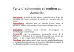
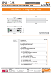
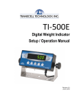
MP-20 Thermal Printer Setup & Operation Manual Revision 1.3 July 17, 2003 2002-2003 Transcell Technology, Inc. Contents subject to change without notice. Transcell Technology, Inc. 975 Deerfield Parkway Buffalo Grove, IL 60089 Tel (847) 419-9180 Fax (847) 419-1515 E-mail: [email protected] Web: www.transcell.net IMPORTANT SAFETY INSTRUCTIONS * Read all of these instructions and save them for later reference. * Follow all warnings and instructions marked on the product. * Unplug this product from the wall outlet before cleaning. Do not use liquid or aerosol cleaners. Use a damp cloth for cleaning. * Do not use this product near water. * Do not place this product on an unstable cart, stand of table. The product may fall, causing serious damage to the product. * Slots and openings on the housing and the back or bottom are provided for ventilation. To ensure reliable operation of the product and to protect it from overheating, do not block or cover these openings. Placing the product on a bed, sofa, rug or a similar surface, can block the openings. This product should never be placed near or over a radiator or heat register. This product should not be placed in a built-in installation unless proper ventilation is provided. * This product should be operated from the type of power source indicated on the marking label. If you’re not sure of the type of power available, consult your dealer or local power company. * Do not allow anything to rest on the power cord. Do not locate this product where the cord will be walked on. * If an extension cord is used with this product, make sure that the total of the ampere ratings on the products plugged into the extension cord do not exceed the extension cord ampere rating. Also, make sure that the total of all products plugged into the wall outlet dose not exceed 15 amperes. * Never push objects of any kind into this product through housing slots as they may touch dangerous voltage points or short out parts that could result in a risk of fire or electric shock. Never spill liquid of any kind on the product. * Except as explained elsewhere in this manual, don’t attempt to service this product yourself. Opening and removing those covers that are marked “Do Not Remove” may expose you to dangerous voltage points or other risks. Refer all servicing on those compartments to service personnel. * Unplug this product from the wall outlet and refer servicing to qualified service personnel under the following conditions: A. When the power cord or plug is damaged or frayed B. If liquid has been spilled into the product. C. If the product has been exposed to rain or water. D. If the product does not operate normally when the operating instructions are followed. Adjust only those controls that are covered by the operating instructions since improper adjustment of other controls may result in damage and will often require extensive work by a qualified technician to restore the product to normal operation. E. If the product has been dropped or the housing has been damaged. F. If the product exhibits a distinct change in performance, indicating a need for service. 1. INTRODUCTION The MP-20 is a thermal printer suitable for use with various data communication devices. This product is extremely compact and features extensive functions suited for a wide range of applications. Please read this manual thoroughly to understand the printer before use. 1.1 Features 1. Compact desktop thermal printer 2. Light weight 3. High speed printing 4. Low power consumption 1.2 Accessories The following attachments are included in this set aside from the printer itself. Please confirm. Paper roll (1 roll) AC adapter (1unit) User’s manual (1 booklet) Interface Cable Gender Changer (9-9 male-male) 1-1 2. TYPE CLASSIFICATIONS 2.1 Type The product is categorized according to the naming plan indicated below. MP-20 Model Name Number of columns (default font) 20 : 20 columns/384 dots per line 2.2 AC adapter Please use the exclusive adapter indicated below. 250115288 (AC 100-240V) 2.3 Specifications Printing method Printing width Number of dots/line Dots density Printing speed Feeding speed Standard paper roll size (W x L) Interface Power Current consumption Weight Dimension (W x D x H) Operation temp. Storage temp. Fonts available Default font Barcode Max. Printable label size (W x L) Error conditions detected 1 2 Thermal dot line printing 48 mm 384 8 dots/mm 18 mm/second1 24 mm/second 57 mm× 36 m (Thermal) Dia = 57 mm Serial Interface (RS-232C) Baud Rate, 9600 Data Bits, 8 Parity, None Stop Bits, 1 DC9V / 2.8A Printing: 800 mA Feeding: 300 mA Stand By: 80 mA Approx. 360g (Paper roll excluded) 120 mm × 170 mm × 92 mm 0 to 50 °C -25 to 65 °C Arial Narrow 14, Arial Narrow 20, Arial 14 Bold, Arial 20 Bold, Lucida 16 Bold, Courier 20 Bold, CHIBLACK 24 CHIBLACK 242 Code 39 50 mm × 100 mm Paper out, Head up, Overheat Version 1.06 or higher only. Lower versions print at 10 mm/second. Version 1.08 or higher only. Lower versions default to Lucida 16 Bold. 2-1 3. EXTERNAL APPEARANCE AND PART DESCRIPTIONS 3.1 External Appearance 6 2 3 5 1 4 7 3.2 Part Descriptions 1. DC Power Jack: Insert one end of the enclosed AC adapter here. 5. Interface Connector: Printer is connected to various hosts via cables. Please ensure that both the printer and the host are turned off before connecting. 2. Power/Status Lamp: Lit when power is turned ON and goes out when turned OFF. Also used to indicate system status. See Section 3.3. 6. Printer Cover: Opened to replace paper roll. 3. CLR Key: Use this key to clear a steady Red Status condition. 7. Print Head Cover: Removed to replace paper roll. 4. LF/FF Key: Paper is fed by one line (LF) when key is pressed and released. Paper is continuously fed (FF) when key is pressed and held. 3-1 3.2 System Status Lamp Condition System Status Description Action Steady Green READY Send command or data to printer Flashing Green Steady Red PROCESSING CMDERR System ready to accept any command and data input System is processing a command(s) Command format error, or command/data buffer overflow Flashing Red SYSERR Amber PENDING Wait for process to finish Clear error state by pressing CLR key, and then resend all commands after the one that caused the error System error. May result from one of the Check paper, printer head, or wait a while for printer to following reasons: Paper out, head in up position, cool down in case of overheat or over heat condition Task pending. Happens after self-test page has Send command to print test page again, or switch to finished another mode and then change pending state to Ready 3-2 4. OPERATION 4.1 Connection of the AC Adapter (1) Connect interface cable between the printer and data communication device using supplied cable. (2) Plug the AC adapter into the DC power jack on the printer. (3) Plug of the AC adapter into a power outlet supplying the designated voltage. (Use of exclusive AC adapter is recommended. Output is DC 9V, 2.8A. Avoid using power sources not conforming to this specification.) The Power/Status Lamp should be green. 4.2 Installing the Thermal Paper Roll NOTE: When the printer is shipped from the factory, the paper roll is pre-installed and the printer is ready to operate. Use these instructions when it becomes necessary to replace the paper roll. (1) Unplug the AC adapter from the printer. (2) Open up the Printer Cover by squeezing at the front to release, then let it fall backwards on its hinges. (3) Remove the Print Head Cover by lifting on the tabs towards the back. Once the back tabs are loose, continue to lift the print head cover off and set aside. (4) Push the green print head release lever down and towards the rear of the printer. (5) Feed new paper roll from the bottom of the print head roller until the paper comes out from the top. Ensure that the paper edge is straight with respect to the roller, i.e. not crooked. (6) Push the green print head release lever up and towards the front of the printer. (7) Use the thumbscrew on the green print head release lever to feed about an inch of paper from the roll. (8) Replace the Print Head Cover by first inserting the front tabs, then installing the rear tabs until the piece is locked into position. Ensure that the paper feeds out from the slot. (9) Close the Printer Cover. (10) Plug the AC adapter back into the printer. (11) After turning ON the printer, press and hold the LF/FF key until 1 or 2 inches of paper is fed out of the printer mechanism. 4.3 Self-Test Printing A self-printing function is incorporated in this product to enable the printer to check itself. This function is triggered by the following procedure. (1) Make sure a paper roll in installed. (2) Unplug the AC adapter from the printer. (3) Press and hold the LF/FF key while plugging the AC adapter back in. Release the LF/FF key after the self-printing operation has started. The printer prints out a test page and then returns to Ready Mode. 4-1 4.4 General Notices (1) Never operate your printer without first loading thermal paper. Any printing without paper or with non-thermal paper may cause damage to printer head. (2) Be careful not to drop any foreign matter, such as paper clips, pins, etc. into your printer. These can cause mechanical and/or electrical problems. (3) Use your printer on a flat, stable desk. (4) Do NOT use an organic solvent (thinner, benzene or the like) to clean the surface of the case. (5) Make sure you unplug power of the printer is turned off whenever you do the following. 1) Taking out any foreign matter that was dropped into the printer. 2) Replacing the paper roll. 4-2 5. SERIAL INTERFACE 5.1 Specifications 1) Synchronization: Asynchronous 2) Baud rate: Fixed at 9,600 Baud / sec 3) Word configuration: Start bits: 1 Data bits: 8 (no parity) Stop bit: 1 4) Signal polarity RS-232C * Mark = Logic “1” (-3 to –12V) * Space = Logic “0” (+3 to +12V) 5) Handshaking control: None 5.2 Connector Pin Assignment 1 2 3 PIN No. PIN NAME FUNCTION 1 2 3 TXD RXD GND Transmitted data Received data Signal ground Note: 1. Signals for RS-232C are based on EIA RS-232C level. Applicable connector (Mini-DIN connector) Printer: Female Cable: Male 5.3 Description of Input / Output Signal (1) I / O signals 1) TXD Serial output data signal. 2) RXD Serial input data signal. Data is ignored when command format error or overrun error has occurred. 3) GND Common ground for the circuit. (2) Data configuration 1) Start bit (1 bit) 2) Data bit (8 bits) 3) Stop bit (1 bit) (3) Electrical characteristics 1) RS-232C circuit Input (RXD) MAX 232 equivalent Mark = (-8V) : Stop bit Space = (+8V) : Start bit 5-1 6. Interface for MP-20 Mini Printer 6.1 Working Modes Name Character Mode (default): Description Prints one line of characters whenever a “carriage return” is received from serial port. Barcode Mode: Prints one line of barcodes whenever “carriage return” is received from serial port. Command-Line Mode: Accepts predefined command lines from serial port. Test Page Mode: Operates a batch of pre-input command lines to print a featured label. Configuration Mode: Restores system default settings including header contents.1 6.2 Accepted Commands in Command-Line Mode: (See Appendix B for examples) Ax,y,rotate,font,reverse,”string” Bx,y,rotate,height,withAscii,”string” Dden Ffont N Qheight,width Lx,y,width,height Xx,y,x1,y1,linewidth Pncp Print one line of characters Print one barcode of characters Set default density Set default font Clear image buffer Set default label size Print a rectangular bar Print a rectangular box Print copies of image buffer Arguments: x y rotate font reverse string height withAscii start position on x axle start position on y axle line orientation font used if reverse printed. 0: No; 1: Yes. characters printed size on y direction if readable characters printed. 0: No; 1: Yes. number of density. 0 – 500. size on x direction end position on x axle end position on y axle width of line used number of copies printed den width x1 y1 linewidth ncp 1 Version 1.07 or higher only. 6-1 6.3 Fonts Used (See Appendix A for sample print outs) Version 1.08 and higher: ARIAL Narrow 14 ARIAL 14 Bold ARIAL Narrow 20 ARIAL 20 Bold COURIER 20 Bold CHIBLACK 24 LUCIDA 16 Bold 1 2 3 4 5 6 7 Version 1.07 and lower: ARIAL Narrow 14 ARIAL 14 Bold ARIAL Narrow 20 ARIAL 20 Bold COURIER 20 Bold LUCIDA 16 Bold 1 2 3 4 5 6 (Default) (Default) 2 0 y 1 Paper direction rotate 3 x 6-2 6.4 Mode-Setting Commands (in effect for all modes): [ESC]@[ESC] Clear command error (function same as CLR key). [ESC]S[ESC] Get system status (return status from serial port). [ESC]M[ESC]mode Mode switching. [ESC]F[ESC]lines Feed lines (in dots). [ESC]P[ESC] Process from pending state. [ESC]H[ESC]headernumber Print header.2 Modes: 1 Character mode 2 Command Line mode 3 Barcode mode 4 Test Page mode 5 Configuration mode2 * When input an empty line (only [LF], or [CR][LF]), process [ESC]F[ESC]16. 6.5 Barcode information 6.5.1 Printable barcode letters: 0-9, A-Z, –, ., [blank space], *, $, /, +, %, a-z (equal to A-Z), _, ~ (equal to – in barcode mode), ,, :, ; (equal to . in barcode mode), # (equal to * in barcode mode), @ (equal to $ in barcode mode), \, | (equal to / in barcode mode), = (equal to + in barcode mode), & (equal to % in barcode mode), others (equal to [blank space]) 6.5.2 Barcode modes: Barcode Mode: Command Line Mode: 2 Consider all input as barcode and print barcode (along x direction) line by line (along y direction) Print barcode on predefined specified input commands. Version 1.07 or higher only. 6-3 6.5.3 Barcode properties: Maximum number of letters printable on paper Start coordinate (x, y) Barcode direction Inter-character gap (dot) Narrow bar width (dot) Wide bar width (dot) Bar height (dot) With human-readable text Human-readable text font Human-readable text position Barcode Mode: 11 (0, 0) X 2 2 5 60 Yes Current font Under barcode (center aligned with barcode) Command Line Mode: Depends on barcode direction and start coordinate On command On command 2 2 5 On command On command Arial 20 bold (bar heigh >= 50) Arial 14 bold (bar height < 50) Under barcode (center aligned with barcode) 6.5.4 Barcode command format: Bx,y,rotate,height,withAscii,”text”↵ (x, y) determines start coordinate rotate determines the barcode direction (0: x; 1: y; 2: -x; 3: -y) height defines bar height withAscii defines whether print human-readable text (0: No; 1: Yes) text is the content text of barcode 6-4 7. CHARACTER SET 7.1 Character codes The printer uses the standard ASCII printable characters plus a few control characters. The control characters are non-printable and are surrounded by brackets. Character <BS> <HT> <LF> <VT> <FF> <CR> <EC> <SP> ! " # $ % & ' ( ) * + , . / 0 1 2 3 4 5 6 7 8 9 : ; < = > ? @ A B C D E F Hex 08 09 0A 0B 0C 0D 1B 20 21 22 23 24 25 26 27 28 29 2A 2B 2C 2D 2E 2F 30 31 32 33 34 35 36 37 38 39 3A 3B 3C 3D 3E 3F 40 41 42 43 44 45 46 Decimal 8 9 10 11 12 13 27 32 33 34 35 36 37 38 39 40 41 42 43 44 45 46 47 48 49 50 51 52 53 54 55 56 57 58 59 60 61 62 63 64 65 66 67 68 69 70 Description BACKSPACE (BS) CHARACTER TABULATION LINE FEED (LF) LINE TABULATION (VT) FORM FEED (FF) CARRIAGE RETURN (CR) ESCAPE (ESC) SPACE EXCLAMATION MARK QUOTATION MARK NUMBER SIGN DOLLAR SIGN PERCENT SIGN AMPERSAND APOSTROPHE LEFT PARENTHESIS RIGHT PARENTHESIS ASTERISK PLUS SIGN COMMA HYPHEN-MINUS FULL STOP SOLIDUS DIGIT ZERO DIGIT ONE DIGIT TWO DIGIT THREE DIGIT FOUR DIGIT FIVE DIGIT SIX DIGIT SEVEN DIGIT EIGHT DIGIT NINE COLON SEMICOLON LESS-THAN SIGN EQUALS SIGN GREATER-THAN SIGN QUESTION MARK COMMERCIAL AT LATIN CAPITAL LETTER LATIN CAPITAL LETTER LATIN CAPITAL LETTER LATIN CAPITAL LETTER LATIN CAPITAL LETTER LATIN CAPITAL LETTER 7-1 (HT) A B C D E F G H I J K L M N O P Q R S T U V W X Y Z [ \ ] ^ _ ` a b c d e f g h I j k l m n o p q r s t u v w x y z { | 47 48 49 4A 4B 4C 4D 4E 4F 50 51 52 53 54 55 56 57 58 59 5A 5B 5C 5D 5E 5F 60 61 62 63 64 65 66 67 68 69 6A 6B 6C 6D 6E 6F 70 71 72 73 74 75 76 77 78 79 7A 7B 7C 71 72 73 74 75 76 77 78 79 80 81 82 83 84 85 86 87 88 89 90 91 92 93 94 95 96 97 98 99 100 101 102 103 104 105 106 107 108 109 110 111 112 113 114 115 116 117 118 119 120 121 122 123 124 LATIN CAPITAL LETTER LATIN CAPITAL LETTER LATIN CAPITAL LETTER LATIN CAPITAL LETTER LATIN CAPITAL LETTER LATIN CAPITAL LETTER LATIN CAPITAL LETTER LATIN CAPITAL LETTER LATIN CAPITAL LETTER LATIN CAPITAL LETTER LATIN CAPITAL LETTER LATIN CAPITAL LETTER LATIN CAPITAL LETTER LATIN CAPITAL LETTER LATIN CAPITAL LETTER LATIN CAPITAL LETTER LATIN CAPITAL LETTER LATIN CAPITAL LETTER LATIN CAPITAL LETTER LATIN CAPITAL LETTER LEFT SQUARE BRACKET REVERSE SOLIDUS RIGHT SQUARE BRACKET CIRCUMFLEX ACCENT LOW LINE GRAVE ACCENT LATIN SMALL LETTER A LATIN SMALL LETTER B LATIN SMALL LETTER C LATIN SMALL LETTER D LATIN SMALL LETTER E LATIN SMALL LETTER F LATIN SMALL LETTER G LATIN SMALL LETTER H LATIN SMALL LETTER I LATIN SMALL LETTER J LATIN SMALL LETTER K LATIN SMALL LETTER L LATIN SMALL LETTER M LATIN SMALL LETTER N LATIN SMALL LETTER O LATIN SMALL LETTER P LATIN SMALL LETTER Q LATIN SMALL LETTER R LATIN SMALL LETTER S LATIN SMALL LETTER T LATIN SMALL LETTER U LATIN SMALL LETTER V LATIN SMALL LETTER W LATIN SMALL LETTER X LATIN SMALL LETTER Y LATIN SMALL LETTER Z LEFT CURLY BRACKET VERTICAL LINE 7-2 G H I J K L M N O P Q R S T U V W X Y Z } ~ <DT> 7D 7E 7F 125 126 127 RIGHT CURLY BRACKET TILDE DELETE (DEL) 7-3 8. EXTERNAL DIMENSIONS 172 mm 92 mm 120 mm 8-1 Appendix A. FONT SAMPLE PRINT OUTS Font 1: Arial Narrow 14 Font 2: Arial 14 Bold Font 3: Arial Narrow 20 A-1 Font 4: Arial 20 Bold Font 5: Courier 20 Bold Font 7: Lucida 16 Bold 1 1 Lucida 16 is Font 6 in Version 1.07 and lower. A-2 Appendix B. COMMAND SET EXAMPLES Command Description Q250,384! Set label size: width 384, length 200 (points). D500! Set density 500. B20,10,0,40,0,"CODE 39"! Draw code-39 barcode of the string “CODE 39”. Start at coordinate x:20, y: 10; direction 0; barcode height 40; no human readable text. B20,80,0,60,1,"Readable"! Draw code-39 barcode of the string “Readable”. Start at coordinate x:20, y: 80; direction 0; barcode height 60; has human readable text. B20,190,0,25,1,"narrow"! Draw code-39 barcode of the string “narrow”. Start at coordinate x:20, y: 190; direction 0; barcode height 25; has human readable text. P1! Print one label. Result: Continued => B-1 Command Description Q140,384! Set label size: width 384, length 140 (points). D500! Set density 500. X10,10,373,130,20! Draw a box. Start at coordinate x:10, y:10; end at x:373, y:130; thickness 20 points. A50,40,0,5,0,"Normal Text"! Write normal text “Normal Text”, start at coordinate x:50, y:40; direction 0; use font Courier-20 (font 5). A50,70,0,5,1,"Reverse Text"! Write reversed text “Reverse Text”, start at coordinate x:50, y:70; direction 0; use font Courier-20 (font 5). P1! Print one label. Result: Continued => B-2 Barcode Mode: Command [ESC]M[ESC]4↵ A1B2C3D4↵ $1,234.56↵ [ESC]M[ESC]2↵ F2↵ [ESC]M[ESC]4↵ $1,234.56↵ [ESC]M[ESC]1↵ Description Switch to Barcode Mode. Print barcode with content “A1B2C3D4”, using current font Print barcode with content “$1,234.56”, using current font Switch to Command Line Mode Change current font to 2 (Arial 14 bold) Switch back to Barcode Mode Print barcode with content “$1,234.56”, using current font (Arial 14 bold) Switch back to text mode (default mode) Result: Continued => B-3 Command Line Mode: Command [ESC]M[ESC]2↵ Q360,240↵ D400↵ B10,5,0,30,1,”A1B2C3D4”↵ B380, 5,1,55,0,”$1,234.56”↵ B250,220,2,60,1,”Verse” ↵ Description Switch to Command Line Mode. Set a 360(wide)*240(long) ticket size Set density 400 Set a barcode “A1B2C3D4”, starting at (10,5), direction x, height 30, with readable text Set a barcode “$1,234.56”, starting at (380, 5), direction y, height 55, without readable text Set a barcode “Verse”, starting at (250,220), direction –x, height 60, with readable text Print defined ticket Switch back to text mode (default mode) P1↵ [ESC]M[ESC]1↵ Result: B-4