1
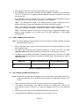
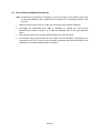
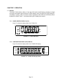
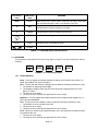
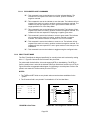
TI-500 / TI-500E Digital Indicator Setup / Operation Manual Revision 2.3 April 20, 2000 2000 Transcell Technology, Inc. Contents subject to change without notice. Transcell Technology, Inc. 35 Waltz Drive Wheeling, IL 60090 USA Tel (847) 419-9180 Fax (847) 419-1515 E-mail: [email protected] Web: www.transcell.net NOTE This equipment has been tested and found to comply with the limits for a Class A digital device, pursuant to Part 15 of the FCC Rules. These limits are designed to provide reasonable protection against harmful interference when the equipment is operated in a commercial environment. This equipment generates, uses and can radiate radio frequency energy and, if not installed and used in accordance with the instructions manual, may cause harmful interference to radio communications. Operation of this equipment in a residential area is likely to cause harmful interference in which case the user will be required to correct the interference at his/her own expense. TABLE OF CONTENTS Page Chapter 1: Introduction To The TI-500/500E Indicator ................................................................ 1-1 Chapter 2: Installation ................................................................................................................ 2-1 2.1 2.2 Chapter 3: ABS Enclosure (TI-500/500E) ................................................................................... 2-1 2.1.1 Connecting the weigh platform ..................................................................... 2-1 2.1.2 Connecting the serial printer, remote display or computer ............................ 2-2 2.1.3 Connecting the power supply........................................................................ 2-2 Stainless Steel Enclosure (TI-500ESS) ..................................................................... 2-2 2.2.1 Connecting the weigh platform ..................................................................... 2-3 2.2.2 Connecting the serial printer, remote display or computer ............................ 2-3 2.2.3 Connecting the power supply........................................................................ 2-3 Configuration ............................................................................................................ 3-1 3.1 Configuration Overview ............................................................................................ 3-1 3.2 Setup (“F”) Menu ...................................................................................................... 3-1 3.3 Chapter 4: 4.1 Chapter 5: 3.2.1 Entering the Setup Menu – ABS Enclosure .................................................. 3-1 3.2.2 Entering the Setup Menu – Stainless Steel Enclosure .................................. 3-1 3.2.3 Navigating in the Setup Menu ...................................................................... 3-1 3.2.4 Notes on the Setup Menu ............................................................................. 3-2 3.2.5 Exiting the Setup Menu – ABS Enclosure..................................................... 3-2 3.2.6 Exiting the Setup Menu – Stainless Steel Enclosure..................................... 3-3 User (“A”) Menu ........................................................................................................ 3-3 3.3.1 Entering the User Menu................................................................................ 3-3 3.3.2 Navigating in the User Menu ........................................................................ 3-3 3.3.3 Notes on the User Menu............................................................................... 3-4 3.3.4 Exiting the User Menu .................................................................................. 3-4 Setup Menu Descriptions and Procedures................................................................. 4-1 Setup Menu Descriptions .......................................................................................... 4-1 User Menu Descriptions and Procedures .................................................................. 5-1 5.1 User Menu Descriptions............................................................................................ 5-1 5.2 User Menu Procedures ............................................................................................. 5-2 5.2.1 ID Number Entry (A8)................................................................................... 5-2 5.2.2 Line Feeds Entry (A9) .................................................................................. 5-2 i Chapter 6: Calibration ................................................................................................................ 6-1 6.1 Calibration Overview ................................................................................................ 6-1 6.2 Zero Calibration (F16)............................................................................................... 6-1 6.3 Span Calibration (F17).............................................................................................. 6-1 6.4 View Calibration Values (F18)................................................................................... 6-2 6.5 Key-in Zero Calibration Value (F19).......................................................................... 6-2 6.6 Key-in Span Calibration Value (F20)......................................................................... 6-3 Chapter 7: 7.1 7.2 Operation.................................................................................................................. 7-1 Display ..................................................................................................................... 7-1 7.1.1 Liquid Crystal Display (LCD)......................................................................... 7-1 7.1.2 Light Emitting Diode (LED) Display .............................................................. 7-1 Keyboard .................................................................................................................. 7-2 7.2.1 7.3 Chapter 8: Function Keys .............................................................................................. 7-2 General Scale Operation .......................................................................................... 7-3 7.3.1 Weighing an item ......................................................................................... 7-3 7.3.2 Taring an item.............................................................................................. 7-3 Legal for Trade Sealing ............................................................................................ 8-1 8.1 ABS Enclosure ......................................................................................................... 8-1 8.2 Stainless Steel Enclosure ......................................................................................... 8-1 Appendix A: Specifications ........................................................................................................... A-1 Appendix B: Serial Port Information.............................................................................................. B-1 B.1 Serial Port Modes ..................................................................................................... B-1 B.1.1 Full Duplex Mode ......................................................................................... B-1 B.1.1.1 Recognized Host Commands........................................................ B-2 B.1.2 Print Ticket Mode ......................................................................................... B-2 B.1.3 Simplex Mode .............................................................................................. B-3 Appendix C: Determining Proper Span Gain (F2).......................................................................... C-1 C.1 Span Gain Overview................................................................................................. C-1 C.2 Setting the initial value for span gain ........................................................................ C-1 C.3 Viewing the internal counts ....................................................................................... C-1 Appendix D: Displayed Error Codes .............................................................................................. D-1 ii LIST OF FIGURES 1-1 2-1 2-2 2-3 2-4 2-5 2-6 2-7 3-1 3-2 3-3 3-4 5-1 6-1 7-1 7-2 7-3 8-1 B-1 B-2 B-3 B-4 B-5 TI-500 Front Panel ............................................................................................................. TI-500/500E Rear Panel..................................................................................................... Color Codes for Shielded Load Cell Cable ......................................................................... Pin Assignments for the Load Cell Port .............................................................................. Pin Assignments for the DSUB9 serial port connector ........................................................ TI-500/500E Main Circuit Board Overview ......................................................................... Connection Assignments for the Load Cell Terminal (J8) ................................................... Connection Assignments for the serial communication Terminal ........................................ Setup Menu Key Assignments............................................................................................ Setup Menu Chart .............................................................................................................. User Menu Key Assignments.............................................................................................. User Menu Chart................................................................................................................ User Menu Key Assignments.............................................................................................. Setup Menu Key Assignments............................................................................................ TI-500 LCD Detail .............................................................................................................. TI-500E LED Display Detail................................................................................................ Function Keys Layout......................................................................................................... TI-500/500E ABS Rear Panel............................................................................................. Cable Diagram for Indicator to IBM PC .............................................................................. Consolidated Controls Demand Mode ................................................................................ Print Ticket......................................................................................................................... Cable Diagram for Indicator to Printer ................................................................................ Consolidated Controls Continuous Mode ............................................................................ 1-1 2-1 2-1 2-1 2-2 2-2 2-3 2-3 3-2 3-2 3-4 3-4 5-2 6-1 7-1 7-1 7-2 8-1 B-1 B-1 B-2 B-2 B-3 LIST OF TABLES 1-1 4-1 6-1 7-1 C-1 TI-500/500E Product Matrix ............................................................................................... Invalid Setup Selections for commercial applications ......................................................... Calibration Value Table...................................................................................................... TI-500/500E Annunciator Definitions .................................................................................. Minimum Recommended Span Gain Table ........................................................................ iii 1-1 4-2 6-2 7-2 C-2 CHAPTER 1: INTRODUCTION TO THE TI-500/500E DIGITAL INDICATORS The TI-500/500E Digital Indicator is a general purpose, industrial grade weight indicator. Three models are currently available, distinguishable by display type and enclosure type. Table 1-1 shows the TI-500/500E product matrix. All models operate identically, can readout up to 50,000 display divisions and can supply enough current for up to 4-350Ω load cells. All setup parameters may be entered via the front panel keys, including calibration. If your Model TI-500/500E Digital Indicator is part of a complete floor scale or has been installed for you, you may skip to Chapter 7 for operating instructions. Prior to using the indicator, please read this chapter carefully and completely. Store the manual in a safe and convenient place so it will be available if you have questions concerning the operation of the scale. If you are an installer, the indicator's installation and wiring instructions are found in Chapter 2. The indicator contains two main setup menus: The Setup (“F”) menu which configures the indicator to your weigh platform and the User (“A”) menu which configures the serial communication port and enables some user options. Chapter 3 gives an overview and explains how to use the five front panel keys to maneuver and save settings in both menus. Chapters 4 and 5 explain the Setup and User Menu options, respectively. Chapter 6 covers system calibration. Prior to installing the indicator, please read this manual carefully and completely. Store the manual in a safe and convenient place so it will be available if you have questions concerning the setup and operation of the scale. MODEL DISPLAY TYPE ENCLOSURE TYPE TI-500E LED (light emitting diode), 0.6" tall ABS, NEMA 12 rated TI-500 LCD (liquid crystal display), 0.75" tall ABS, NEMA 12 rated TI-500ESS LED (light emitting diode), 0.6" tall Stainless Steel, NEMA 4X rated TABLE 1-1: TI-500/500E Product Matrix pcs O lb oz TE OK kg % G LO N n max = 5000 CLASS III lb kg HI ZERO NET GROSS TARE PRINT MODEL Transcell Technology TI-500 FIGURE 1-1: TI-500 Front Panel Page 1-1 CHAPTER 2: INSTALLATION 2.1 ABS ENCLOSURE (TI-500/500E) For indicators contained in the standard ABS enclosure, the rear panel contains all connectors necessary to make the appropriate connections to the weigh platform, printer, remote display and power supply. Power Switch DC Jack Setup/Calibration Switch LOAD CELL Connector RS 232 Figure 2-1: TI-500/500E ABS Enclosure Rear Panel 2.1.1 CONNECTING THE WEIGH PLATFORM The indicators mounted in an ABS enclosure ship with a 15 ft shielded load cell cable for connection to weigh platform’s load cell(s) or junction box. 1. Plug the cable’s 14-pin Centronics-type connector into the load cell port on the rear panel of the indicator. 2. Wire the bare wires and shield to the weigh platform’s load cell(s) or junction box using the color codes shown in Figure 2-2. Color RED BLK GRN WHT Wire Name +Excitation - Excitation +Signal - Signal Figure 2-2: Color Codes for Shielded Load Cell Cable 3. If you do not wish to use the shielded load cell cable, you may use own, following the pin assignments shown in Figure 2-3. (A 14-pin Male Centronics-type connector is required). Pin Nos. 1/8 3/10 5/12 7/14 Pin Name +Excitation - Excitation +Signal 7 5 3 1 - Signal 14 12 10 8 Figure 2-3: Pin assignments for the Load Cell Port Page 2-1 2.1.2 CONNECTING THE SERIAL PRINTER, REMOTE DISPLAY OR COMPUTER The TI-500/500E indicator comes standard with one full duplex RS-232 serial port, designed for connection to either a PC or a serial printer. The same port may be also used as a simplex, RS-232 port designed for connection to a remote display. Figure 2-4 shows the serial port pinout. Refer to Appendix B for some suggested cable diagrams. (A 9-pin pin Male D-type connector is required). 1. Plug the serial printer, remote display or computer communication cable (not included) directly into the DSUB9 serial port connector. 5 Pin No. Pin Name Signal Level 2 3 5 Receive Data Transmit Data Signal Ground RS-232 RS-232 RS-232 3 2 Front View Figure 2-4: Pin assignments for the DSUB9 serial port connector 2.1.3 CONNECTING THE POWER SUPPLY 1. The indicator ships standard with an external AC to DC adapter. Simply plug the AC adapter into the indicator’s DC Power Jack first, and then plug into a standard wall outlet. Make sure that the AC voltage appearing at the wall outlet matches the input voltage marked on the AC adapter. 2.2 STAINLESS STEEL ENCLOSURE (TI-500ESS) For indicators contained in a stainless steel enclosure, the rear cover must first be removed to make the appropriate connections to the weigh platform, printer, remote display and power supply. To remove the rear cover, simply remove the screws that secure it to the enclosure and set aside. NOTE: The rear cover must remain off to access the Setup Menu and calibration procedures. J4 J6 CPU JP2 EPROM J1 J8 E+ S+ E- S- SH J3 P+ P- TXD RXD GND +5 Figure 2-5: TI-500ESS Main Circuit Board Overview Page 2-2 2.2.1 CONNECTING THE WEIGH PLATFORM 1. Connect your shielded load cell cable (not included) to terminal J8 on the main board. Connection assignments for the Load Cell Terminal (J8) are shown in Figure 2-6. J8 E+ S+ E– S– Figure 2-6: Connection assignments for the Load Cell Terminal (J8) 2.2.2 CONNECTING THE SERIAL PRINTER, REMOTE DISPLAY OR COMPUTER The TI-500/500E indicator comes standard with one full duplex RS-232 serial port, designed for connection to either a PC or a serial printer. The same port may be also used as a simplex, RS-232 port designed for connection to a remote display. For indicators housed in a Stainless Steel enclosure, this port is realized in J3. Connection assignments for all serial communication terminals are shown in Figure 2-7. NOTE: Do not connect any RS-232 equipment to the “+5V” terminal (not shown). 1. Connect your serial printer, remote display or computer communication cable (not included) to terminal J3 on the main board. J3 TXD RXD GND Figure 2-7: Connection assignments for the serial communication terminal 2.2.3 CONNECTING THE POWER SUPPLY 1. The indicator ships standard with an external AC to DC adapter. Simply plug the AC adapter into the indicator’s DC Power Jack first, and then plug into a standard wall outlet. Make sure that the AC voltage appearing at the wall outlet matches the input voltage marked on the AC adapter. Page 2-3 CHAPTER 3: CONFIGURATION 3.1 CONFIGURATION OVERVIEW The indicator contains two main setup menus: The Setup (“F”) menu which configures the indicator to your weigh platform and the User (“A”) menu which configures the serial communication port and enables some user options. The Setup and User menus consist of several menu selections, each with its own sub-menu of choices. To set up the indicator, you must first enter the appropriate menu mode. Once there, four of the front panel keys become directional navigators to move around in the menus, and one key is used to save or SET the selections. 3.2 SETUP (“F”) MENU 3.2.1 ENTERING THE SETUP MENU – ABS ENCLOSURE 1. Power off the indicator by unplugging the power source. 2. On the back cover, move the Setup/Calibration Switch to the opposite position. 3. Power on the indicator by plugging in the power source. The indicator shows ” F 1” to indicate that you are in Setup Menu mode. Note: Access to the Setup/Calibration Switch is inhibited if the indicator has been sealed for commercial use. For more information, please refer to Chapter 8. 3.2.2 ENTERING THE SETUP MENU – STAINLESS STEEL ENCLOSURE 1. Power off the indicator by unplugging the power source. 2. Remove the back cover and locate jumper JP2. 3. Position the shunt block as shown at right. JP2 Note: On certain models, the shunt block position will be exactly the opposite. 4. Power on the indicator by plugging in the power source. The indicator shows ” F 1” to indicate that you are in Setup Menu mode. Note: Access to the back cover is inhibited if the indicator has been sealed for commercial use. For more information, please refer to Chapter 8. 3.2.3 NAVIGATING IN THE SETUP MENU Use the directional keys shown in Figure 3-1 to move around in the Setup Menu Chart shown in Figure 3-2 on the following page. 1. To move to a new “F” heading, use the TARE (left) or PRINT (right) key to move right or left in the Setup Menu Chart. 2. To move to the selection level, press the ZERO (down) key once. The current saved selection is shown. 3. To view the available selections for the current “F” heading, use the TARE (left) or PRINT (right) key to move through the selection field. 4. To save a new selection, press the NET/GROSS (Set) key .To exit without saving, press the lb/kg (up) key to return to the current “F” heading. 5. Repeat Steps 1 through 4 until the Setup Menu is programmed. Page 3-1 SET Figure 3-1: Setup Menu Key Assignments F1 Grads F2 Span Gn. F3 Zero Band 0d 0.5d 1d F4 Zero Range F5 Mot. Band 3d 5d F6 Dig. Filter 1d 3d 5d 10d F8 Calib. Unit 0d 2% 1d 9d 1 2 4 8 100% 1.9% 25 50 75 100 150 200 F7 Ovld. Limit lb kg 500 1000 1500 2000 2500 3000 4000 5000 6000 8000 10000 12000 20000 30000 40000 50000 F9 Dsp. Div. 1 2 5 F10 Dec. Pt. F16 Zero Calib. F17 Span Calib. F18 Cal. View F19 Key-in Zero F20 Key-in Span Press ZERO key to begin Press ZERO key to begin Press ZERO key to begin Press ZERO key to begin Press ZERO key to begin 0 0.0 0.00 0.000 0.0000 00 Figure 3-2: Setup Menu Chart 3.2.4 NOTES ON THE SETUP MENU 1. There is an F21 sub-menu present that is for FACTORY USE ONLY! 2. Detailed descriptions of the setup menu parameters can be found in Chapter 4 of this manual. 3. The User (“A”) menu sub-menus appear when scrolling left or right from the “F” menu. 3.2.5 EXITING THE SETUP MENU – ABS ENCLOSURE 1. Power off the indicator by unplugging the power source. 2. On the back cover, move the Setup/Calibration Switch back to its original position. 3. Power on the indicator by plugging in the power source. The display will go through a digit check, then settle into Normal Operating mode. All front panel keys will now return to their normal mode of operation. Page 3-2 3.2.6 EXITING THE SETUP MENU – STAINLESS STEEL ENCLOSURE 1. Power off the indicator by unplugging the power source. 2. Position the shunt block as shown at right. JP2 Note: On certain models, the shunt block position will be exactly the opposite. 3. Power on the indicator by plugging in the power source. The display will go through a digit check, then settle into Normal Operating mode. All front panel keys will now return to their normal mode of operation. 3.3 USER (“A”) MENU 3.3.1 ENTERING THE USER MENU 1. Enter the Setup (“F”) menu by following the directions in Section 3.2.1 or 3.2.2. 2. Use the right or left directional keys shown in Figure 3-3 to move right or left in the Setup (“F”) menu until the indicator shows ” A 1”. Note: On certain older models, the User (“A”) Menu is independent from the Setup (“F”) Menu. To enter the User Menu on these models, first exit the Setup Menu Mode. Turn the unit off, then press and hold the lb/kg key while powering the unit back on. When the screen shows ” A 1” you may release the lb/kg key. 3.3.2 NAVIGATING IN THE USER MENU Use the directional keys shown in Figure 3-3 to move around in the User Menu Chart shown in Figure 3-4 on the following page. 1. To move to a new “A” heading, use the TARE (left) or PRINT (right) key to move right or left in the User Menu Chart. 2. To move to the selection level, press the ZERO (down) key once. The current saved selection is shown. 3. To view the available selections for the current “A” heading, use the TARE (left) or PRINT (right) key to move through the selection field. 4. To save a new selection, press the NET/GROSS (Set) key .To exit without saving, press the lb/kg (up) key to return to the current “A” heading. 5. Repeat Steps 2 through 5 until the User Menu is programmed. Page 3-3 SET Figure 3-3: User Menu Key Assignments A1 Baud Rate A2 Data Bits, Parity A3 Transmission Mode 8n 7O 7E 7n C A4 Display Check A5 Enable lb/kg Key Press ZERO key to begin d 0 1 1200 2400 4800 9600 A6 Serial Port Mode 0 1 A7 ID No. Enable 0 1 A8 ID No. Entry Press ZERO key to begin A9 No. of Line Feeds Press ZERO key to begin Figure 3-4: User Menu Chart 3.3.3 NOTES ON THE USER MENU 1. Detailed descriptions of the user menu parameters can be found in Chapter 5 of this manual. 3.3.4 EXITING THE USER MENU 1. Exit the User (“A”) menu by following the directions in Section 3.2.5 or 3.2.6. The display will go through a digit check, then settle into Normal Operating mode. All front panel keys will now return to their normal mode of operation. Page 3-4 CHAPTER 4: SETUP MENU DESCRIPTIONS AND PROCEDURES 4.1 SETUP MENU DESCRIPTIONS This section provides more detailed descriptions of the selections found in the Setup Menu Chart. Factory-set defaults are shown in bold with a checkmark (√). Table 4-1 shows the selections that are not allowed for “Legal-for-Trade” applications: NAME/CODE DESCRIPTION CODE/VALUE F1 Graduations Specifies number of full-scale graduations. Value should be consistent with legal requirements and environmental limits on the useful system resolution. 500 1,500 2,500 4,000 6,000 10,000 20,000 40,000 F2 Span Gain Span Gain is related to A/D integration time. The larger the span gain, the higher the internal resolution, but the slower the update speed. Note that the scale must be re-calibrated whenever this parameter is altered. See Appendix C for more information. 25 75√ √ 150 F3 Zero Track Band Selects the range within which the scale will automatically zero. Note that the scale must be in standstill to automatically zero. Selections are in Display Divisions. 0d 0.5d√ √ 1d 3d 5d F4 Zero Range Selects the range within which the scale may be zeroed. Note that the indicator must be in standstill to zero the scale. 100%√ √ 1.9% F5 Motion Band Sets the level at which motion is detected by comparing the present display update with the previous one. If motion is not detected for two seconds or more, scale is in standstill and can process a Print or Zero command. Maximum value varies depending on local regulations. 1d√ √ 3d 5d 10d F6 Digital Filter Averages weight readings to produce higher stability. The higher the filter setting, the greater the stability but the slower the indicator’s response time. Choose 8 unless a very fast response is needed. 1 4 F7 Overload Limit Selects the desired formula which determines the point at which the indicator shows overload. All selections are based on the primary unit selected in F8. FS FS + 2%√ √ FS + 1d FS + 9d "FS" = Full scale in primary units. F8 Calib. Unit Selects the primary base unit to be used in the calibration process. Also the default unit for normal operation. "1" = primary unit is lb. "2" = primary unit is in kg. Page 4-1 1√ √ 2 1,000 2,000 3,000 5,000√ √ 8,000 12,000 30,000 50,000 50 100 200 2 8√ √ NAME/CODE DESCRIPTION CODE/VALUE F9 Display Divisions Determines the desired weight increments. Value should be consistent with legal requirements. 1√ √ 2 5 F10 Decimal Pt. Determines location of the decimal point. 0√ √ 0.00 0.0000 F16 Zero Calibration Places indicator into the zero calibration routine. Scrolling down with the ZERO key one level begins the procedure. Press ZERO key to begin sequence F17 Span Calibration Places indicator into the span calibration routine. Scrolling down with the ZERO key one level begins the procedure. Press ZERO key to begin sequence F18 View Calibration Actuates the function that allows you to view both the zero and span calibration value. The values displayed in this function are valid only after Calibration (F16 & F17) has been successfully completed. Scrolling down with the ZERO key one level begins the procedure. Press ZERO key to begin sequence F19 Key-in Zero Allows you to key-in known zero calibration value in case of memory loss in the field. Scrolling down with the ZERO key one level begins the procedure. Press ZERO key to begin sequence F20 Key-in Span Allows you to key-in a known span calibration value in case of memory loss in the field. Scrolling down with the ZERO key one level begins the procedure. Press ZERO key to begin sequence F21 Factory Reset This sub-menu will reset all parameters in the “F” and “A” menu to the default settings. USE WITH CAUTION! Press the ZERO key twice to execute. SUB-MENU TITLE 0.0 0.000 00 SELECTIONS F1 Graduations 6,000 10,000 20,000 40,000 F3 Zero Tracking Band (SAZSM) 0d 5d F5 Motion Band 3d 5d 10d F6 Digital Filter 1 2 4 8,000 12,000 30,000 50,000 Table 4-1: Invalid Setup Menu selections for commercial applications Page 4-2 CHAPTER 5: USER MENU DESCRIPTIONS AND PROCEDURES 5.1 USER MENU DESCRIPTIONS This section provides more detailed descriptions of the selections found in the User Menu Chart. Factory-set defaults are shown in bold with a checkmark (√). NAME/CODE DESCRIPTION CODE/VALUE 2400√ √ 9600 A1 Baud Rate Selects the baud rate for data transmission through the serial port. 1200 4800 A2 Data Bits and Parity Selects the number of data bits and parity of serial transmission. "8n" = 8 data bits with no parity bit and one stop bit "7O" = 7 data bits with odd parity bit and one stop bit "7E" = 7 data bits with even parity bit and one stop bit "7n" = 7 data bits with no parity bit and two stop bits 8n√ √ 7O 7E 7n A3 Mode of Serial Transmission Selects when data will be sent out of the serial port to a printer or computer: "C" = Continuous mode; send data continuously "d" = Demand mode; send data when a PRINT command is issued from the printer, computer, or indicator. C d√ √ A4 Display Check Actuates the function that illuminates all digit segments, decimal points, and LCD annunciators in a test sequence. Pressing the ZERO key to scroll down one level begins the test sequence. Press ZERO key to begin sequence A5 Disable the lb/kg Key Allows the lb/kg key to be disabled so that an operator cannot accidentally press the key and change the displayed units. "0" = Disable the lb/kg key "1" = Enable the lb/kg key 0 1√ √ A6 Serial Port Mode Selects the mode of the RS-232 serial port: Refer to Appendix B for more information. "0" = Full Duplex Mode "1" = Print Ticket Mode 0√ √ 1 A7 ID No. Enable Allows the ID number to be disabled in the Print Ticket mode. Valid only when A6 is set to “1”. "0" = Disable the ID No. "1" = Enable the ID No. 0√ √ 1 A8 ID No. Entry Actuates the function that allows entry of a new ID No. Valid only when A6 is set to “1”. Pressing the ZERO key to scroll down one level begins the sequence. 0 - 199999 (500) 0 - 999999 (500E) 123456√ √ A9 No. of Line Feeds Actuates the function that allows entry of the desired number of line feeds to be printed in Print Ticket Mode. Valid only when A6 is set to “1”. Pressing the ZERO key to scroll down one level begins the sequence. 0 - 99 5√ √ Page 5-1 5.2 USER MENU PROCEDURES This section provides instructions for all of the User Menu procedures. 5.2.1 ID Number Entry (A8) 1. While in the User Menu mode, scroll to "A 8", then scroll down once using the ZERO key to enter the ID Number menu. 2. The display will momentarily show "ID NO", followed by a value with one flashing digit. This value will be the current ID number value. 3. Use the four directional keys (shown in Figure 5-1 below) to adjust the displayed value to the actual ID Number value. Increase the flashing digit by pressing the lb/kg key. Decrease the flashing digit by pressing the ZERO key. Pressing the PRINT key or the TARE key will change the position of the flashing digit. USER MODE KEY FUNCTIONS lb/kg ZERO NET GROSS TARE PRINT SET Figure 5-1: User Menu Key Assignments 4. 5.2.2 After setting the exact value, press the NET/GROSS key to save the ID Number value. The display will show "SET" momentarily, then revert back up to A8. LF (Line Feeds) Number Entry (A9) 1. While in the User Menu mode, scroll to "A 9", then scroll down once using the ZERO key to enter the Line Feeds menu. 2. The display will momentarily show "LF", followed by the current line feeds value. 3. Use the four directional keys (shown in Figure 5-1 above) to adjust the displayed value to the actual line feeds value. Increase the flashing digit by pressing the lb/kg key. Decrease the flashing digit by pressing the ZERO key. Pressing the PRINT key or the TARE key will change the position of the flashing digit. 4. After setting the exact value, press the NET/GROSS key to save the line feeds value. The display will show "SET" momentarily, then revert back up to A9. Page 5-2 CHAPTER 6: CALIBRATION 6.1 CALIBRATION OVERVIEW The indicator is calibrated by following the procedures embedded in F16 (Zero) and F17 (Span) of the Setup Menu. Each procedure enters a value into the indicator's non-volatile memory - F16 the zero value (deadweight) and F17 the span value (test weight). The minimum test weight that can be used is 1% of full-scale capacity. After the two calibration procedures are executed successfully, you should record both calibration values in Table 6-1 using the F18 View procedure. In the unlikely event that either value is lost while in the field, the setup menu makes provisions for re-entering these values via F19 and F20, thus eliminating the need for re-calibration with test weights. NOTE: This chapter assumes that the indicator is in Setup (“F”) Menu mode. If the indicator is not in Setup Menu mode, refer to Chapter 3 for instructions. 6.2 ZERO CALIBRATION (F16) 1. While in the Setup mode, scroll to "F 16", then scroll down once using the ZERO key to enter zero calibration menu. The display will momentarily show "C 0" followed by a value. This value is the internal A/D count and can prove useful when trying to troubleshoot setup problems. 2. After making sure that there are no test weights on the platform, press the ZERO key again to zero out the displayed value. 3. Press the NET/GROSS key to save the zero point value. The display will show "EndC0" momentarily, then revert back up to F16. At this time, proceed to the F17 span calibration to complete indicator calibration. 6.3 SPAN CALIBRATION (F17) 1. While in the Setup mode, scroll to "F 17", then scroll down once using the ZERO key to enter span calibration menu. 2. The display will momentarily show "C 1" for the span calibration, followed by a value with one flashing digit. This value will be zero with the Decimal Point parameter selected in F10. Place the test weight on the weighing mechanism. 3. Use the four directional keys (shown in Figure 6-1 below) to adjust the displayed value to the actual test weight value. Increase the flashing digit by pressing the lb/kg key. Decrease the flashing digit by pressing the ZERO key. Pressing the PRINT key or the TARE key will change the position of the flashing digit. SETUP MODE KEY FUNCTIONS lb/kg ZERO NET GROSS TARE PRINT SET Figure 6-1: Setup Menu Key Assignments Page 6-1 4. After setting the exact value, press the NET/GROSS key to save the value. 5. If the calibration was successful, the display will show "EndC1" momentarily, then revert back up to F17. At this time it is suggested that the calibration values be recorded for future use (see Section 6.4). 6. If the calibration was not successful, one of the error messages below will appear. Take the indicated action to correct the problem, then perform a new calibration. "Err0" - The calibration test weight or the adjusted keyed-in weight is larger than the full capacity of the scale. Change the calibration test weight or check the input data. "Err1" - The calibration test weight or the adjusted keyed-in weight is smaller than 1% of the full capacity of the scale. Change the calibration test weight or check the input data. "Err2" - The internal resolution of the scale is not high enough to accept the calibration value. Select a larger parameter for the Span Gain (F2). SEE APPENDIX C FOR MORE INFORMATION. 6.4 VIEW CALIBRATION VALUES (F18) Note: The values displayed in this procedure are valid only after a successful calibration has been performed using F16 and F17. 1. While in the Setup mode, scroll to "F 18", then scroll down once using the ZERO key to enter View calibration menu. 2. The display will momentarily show "CAL 0" followed by a value. This value is the zero calibration value and should be recorded in the table below. Press any key to continue. 3. The display will momentarily show "CAL 1" followed by another value. This value is the span calibration value and should also be recorded in the table below. Press any key to return to upper level (F18). INDICATOR ZERO CALIBRATION VALUE SPAN CALIBRATION VALUE S/N: Table 6-1: Calibration Value Table 6.5 KEY-IN ZERO CALIBRATION VALUE (F19) Note: This procedure is intended for emergency use only in the case of non-volatile memory loss. A valid zero calibration value, obtained from a successful F16 calibration procedure, must be used. 1. While in the Setup mode, scroll to "F 19", then scroll down once using the ZERO key. 2. The display will momentarily show "CAL 0", followed by a flashing zero. Use the four directional keys (shown in Figure 6-1) to adjust the displayed value to the zero calibration value. 3. After setting the exact value, press the NET/GROSS key to save the value. 4. The display will show "E CAL 0" momentarily, then revert back up to F19. Page 6-2 6.6 KEY-IN SPAN CALIBRATION VALUE (F20) Note: This procedure is intended for emergency use only in the case of non-volatile memory loss. A valid span calibration value, obtained from a successful F17 calibration procedure, must be used. 1. While in the Setup mode, scroll to "F 20", then scroll down once using the ZERO key. 2. The display will momentarily show "CAL 1", followed by a flashing zero. Use the four directional keys (shown in Figure 6-1) to adjust the displayed value to the span calibration value. 3. After setting the exact value, press the NET/GROSS key to save the value. 4. If the entered value is greater than zero, the display will show "E CAL 1" momentarily, then revert back up to F20. If a value of zero is entered, the indicator will briefly show "Err 5", then revert back to the screen described above in Step # 2. Page 6-3 CHAPTER 7: OPERATION 7.1 DISPLAY The Model TI-500 indicator utilizes a 5-1/2 digit LCD (Liquid Crystal Display) to display the weight and system information while the Model TI-500E indicator utilizes a 6-digit LED (Light Emitting Diode) display. Typically, LCD’s are used for outdoor applications while LED’s are used indoors where brightness is needed. Table 7-1 summarizes both types of display annunciators. 7.1.1 LIQUID CRYSTAL DISPLAY (LCD) Figure 7-1 shows the display detail of the TI-500 LCD. pcs O lb oz TE HI OK kg % G LO N FIGURE 7-1: TI-500 LCD Detail 7.1.2 LIGHT EMITTING DIODE (LED) DISPLAY Figure 7-2 shows the display detail of the TI-500E LED display. lb GROSS NET kg TARE PCS ZERO STABLE FIGURE 7-2: TI-500E LED Display Detail Page 7-1 LCD Annunciator LED Annunciator MEANING è0ç ZERO Better known as the “Center of Zero” annunciator, this light is active whenever the displayed weight is within ± 0.25 divisions of true zero. N NET G GROSS Indicates that the indicator is displaying net weight. Indicates that the indicator is displaying gross weight. TARE Indicates that a tare weight has been established in the system. lb, kg Indicates the unit of the displayed weight. TE lb, kg STABLE This light is on whenever the scale is stable. TABLE 7-1: TI-500/500E Annunciator Definitions 7.2 KEYBOARD The keyboard is composed of five function keys. Refer to Figure 7-3 for the overall layout and key locations. lb kg ZERO NET GROSS TARE PRINT FIGURE 7-3: Function Keys Layout 7.2.1 FUNCTION KEYS lb/kg – This key toggles the indicator between lb and kg units if enabled in the User (“A”) Menu. See Chapter 5 for more information. Zero - This key sets the indicator to display zero provided the following conditions are met: 1. The indicator is displaying Gross weight. 2. The displayed weight is within the zero reset range that is programmed in F4 of the Setup (“F”) Menu. 3. The scale is not in motion. 4. The scale is not in overload (see Appendix D for error codes). Net/Gross - This key toggles the indicator between Gross weight and Net weight only if a Tare has been established. Tare - This key is used to establish a Tare provided the following conditions are met: 1. The indicator is not at or below Gross zero. 2. The scale is not in motion. 3. The scale is not in overload (see Appendix D for error codes). Print - This key is used to send weight information out to the serial port provided the following conditions are met: 1. The scale is not in motion. 2. The scale is not in overload (see Appendix D for error codes). Page 7-2 7.3 GENERAL SCALE OPERATION 7.3.1 WEIGHING AN ITEM 1. Select the desired weighing unit by pressing the lb/kg key until that unit is indicated on the display. 2. If necessary, press the ZERO key to obtain a weight reading of zero. 3. Place the object to be weighed on the scale’s platter and allow the weight indication to stabilize. If the item weight exceeds the scale’s weight capacity, it displays “pppppp”. 4. Read the weight shown on the display. 7.3.2 TARING AN ITEM To weigh an item in a container, the weight of that container must first be subtracted from the overall weight to obtain an accurate weight reading. This is known as taring. 1. Select the desired weighing unit by pressing the lb/kg key until that unit is indicated on the display. 2. If necessary, press the ZERO key to obtain a weight reading of zero. 3. Place the empty container on the scale’s platter and allow the weight indication to stabilize. 4. Press the TARE key. The display shows zero weight and turns the NET annunciator on. 5. Place the material to be weighed in the container and allow the weight indication to stabilize. 6. Read the weight shown on the display. 7. You may toggle between the gross weight and the net weight by pressing the NET/GROSS key. Page 7-3 CHAPTER 8: LEGAL FOR TRADE SEALING 8.1 ABS ENCLOSURE The TI-500/500E indicator in the ABS enclosure can be sealed for commercial (Legal for Trade) applications as follows. 1. Power off the indicator by unplugging the power source. 2. On the back of the indicator, locate the Setup/Calibration Slide Switch Cover Plate (see illustration below). 3. Thread a wire security seal through both drilled head screws securing the calibration switch cover. Power Switch DC Jack Setup/Calibration Switch RS 232 LOAD CELL Connector Figure 8-1: TI-500/500E ABS Rear Panel 8.2 STAINLESS STEEL ENCLOSURE The TI-500ESS indicator in the stainless steel enclosure can be sealed for commercial (Legal for Trade) applications as follows. 1. Power off the indicator by unplugging the power source. 2. Locate the two adjacent drilled head screws securing the rear cover. 3. Thread a wire security seal through both drilled head screws securing the rear cover. Page 8-1 APPENDIX A: SPECIFICATIONS ANALOG SPECIFICATIONS Full Scale Input Signal Minimum Sensitivity - Non H-44 Minimum Sensitivity - H-44 Input Impedance Internal Resolution Display Resolution Measurement Rate System Linearity Calibration Method Excitation Voltage 30mV, including dead load 0.4 µV / grad 1.0 µV / grad 30MΩ, typical Approximately 260,000 counts 50,000 display division max 10 Meas/sec, nominal Within 0.02% of FS Software Calibration, with long term storage in EEPROM +10VDC, 4 x 350Ω load cells DIGITAL SPECIFICATIONS Microcomputer Digital Filtering Intel 80C32 Program Memory: EEPROM: Software selectable 32K x 8, external to µC 64 x 16, external to µC SERIAL COMMUNICATIONS Serial Port Full Duplex, 1200, 2400, 4800, 9600 Baud 8 data bits, no parity, 1 stop bit 7 data bits, odd parity, 1 stop bit 7 data bits, even parity, 1 stop bit 7 data bits, no parity, 2 stop bits OPERATOR INTERFACE Display - TI-500E/500ESS Display - TI-500 Additional Symbols Keyboard 0.56" (14 mm) 7-segment, Led, 6 Digit 0.75" (19 mm) 7-segment, Liquid Crystal, 5½ Digit Net, Gross, Stable, Tare, lb, kg, Zero 5-key flat membrane panel POWER AC Adapter DC Power Consumption - TI-500 DC Power Consumption - TI-500E 12 VDC @ 500mA 80mA + 30mA/350Ω Load Cell 200mA + 30mA/350Ω Load Cell ENVIRONMENTAL Operating Temperature Storage Temperature –10° to +40° C -25° to +70° C MECHANICAL Overall Dimensions – ABS Overall Dimensions – Stainless 3.2" x 6.8" x 2.3" (81mm x 173mm x 57mm) 5.5" x 8.9" x 2.8" (140mm x 225mm x 72mm) APPROVALS NTEP COC # 94-080A2 Page A-1 APPENDIX B: SERIAL PORT INFORMATION B.1 SERIAL PORT MODES B.1.1 FULL DUPLEX MODE The Full Duplex Mode provides a Demand serial transmission mode and is selected by setting A3 to “d” and A6 to “0”. The Demand mode allows control from a host device, usually a PC, and can be activated by pressing the PRINT key on the indicator’s front panel. Figure B-1 shows a suggested cable diagram for interface to a PC. Figure B-2 shows the serial data format for the Demand Mode. INDICATOR PC RXD 2 TXD 3 S. GND 5 2 RXD 3 TXD 5 S. GND 4 DTR 6 DSR 8 CTS DSUB9 DSUB9 FIGURE B-1. Cable Diagram for Indicator to IBM PC <STX> <POL> xxxxx.xx Start Transmission Polarity: <SP> = Positive "–" = Negative Weight Data <SP> <LB/KG> Space <SP> <GR/NT> Space Units: lb = pound kg = kilogram pc = pieces cu = cusotm unit <CR> <LF> Carriage Return Gross/Net: GR = Gross NT = Net FIGURE B-2. Consolidated Controls Demand Mode Page B-1 Line Feed B.1.1.1 RECOGNIZED HOST COMMANDS “P” - This command is sent to the indicator to print the indicated display. The indicator will not respond if the scale is in motion, positive overload or negative overload. “Z” - This command is sent to the indicator to zero the scale. The indicator will not respond if the scale is in motion, positive overload or negative overload. The indicator will also not respond if it is not in gross mode or within the zero range specified in F4 of the Setup Menu. “T” - This command is sent to the indicator to tare the scale. The indicator will not respond if the scale is in motion, positive overload or negative overload. The indicator will also not respond if it displaying a negative gross value. “G” - This command is sent to the indicator to revert to gross mode. The indicator will not respond if the scale is in motion, positive overload or negative overload. The indicator will also not respond if it is not in net mode. “N” - This command is sent to the indicator to revert to net. The indicator will not respond if the scale is in motion, positive overload or negative overload. The indicator will also not respond if it is not in gross mode or a tare has yet to be established. “C” - This command is sent to the indicator to toggle among the configured units. B.1.2 PRINT TICKET MODE The Print Ticket Mode is designed specifically for a serial printer and is selected by setting A6 to “1”. Figure B-3 shows the fixed format of the print ticket. For printers with limited buffers, this mode supports DTR pin handshaking. The DTR pin from the serial printer is wired to the indicator’s RXD pin which then functions as a CTS pin. Figure B-4 shows a suggested cable diagram for interfacing to a serial printer. Refer to the printer’s user manual to confirm which pin is the DTR pin. NOTES: 1. The TARE and NET fields are not printed unless a tare has been established in the system. 2. The ID number field is not printed if it is disabled in A7 of the User Menu. INDICATOR ID. NO. GROSS TARE NET 123456 25.00 LB 1.48 LB 23.52 LB CTS 2 TXD 3 S. GND 5 DSUB9 FIGURE B-3. Print Ticket PRINTER 3 RXD 20 DTR 7 S. GND DSUB25 FIGURE B-4. Cable Diagram for Indicator to Printer Page B-2 B.1.3 SIMPLEX MODE The Simplex Mode provides a continuous serial transmission mode and is selected by setting A3 to “C” and A6 to “0”. The Continuous mode is used to interface to computers, scoreboards, and other remote devices requiring constant data updating. The transmission occurs at the end of each display update. Figure B-5 shows the serial data format for Continuous Mode. <STX> <POL> xxxxx.xx Start Transmission Polarity: <SP> = Positive "–" = Negative Weight Data <L/K> <G/N> Gross/Net: G = Gross N = Net Units: L = pound K = kilogram P = pieces C = custom units <STAT> <CR> <LF> Carriage Return Line Feed Status: <SP> = Valid M = Motion O = Over/under range FIGURE B-5. Consolidated Controls Continuous Mode Page B-3 APPENDIX C: DETERMINING PROPER SPAN GAIN (F2) C.1 SPAN GAIN OVERVIEW The Span Gain parameter found in F2 of the Setup Menu is directly related to the ADC (Analog to Digital Converter) integration time. This means that the lower the setting, the higher the number of measurements per second. A span gain setting of 25 produces about 25 to 30 measurements per second, while a span gain of 200 produces only about 3 or 4 measurements per second. There is really no wrong setting for span gain – except in two cases. Using a low setting for a high resolution, low output system could yield instability. Using a high setting in a high output system could yield non-linearity. C.2 SETTING THE INITIAL VALUE FOR SPAN GAIN 1. Determine the number of desired external graduations and choose the corresponding value listed in Table C-1 under the number closest to your full-scale input range in millivolts. 2. Enter the Setup Menu and save this number for the Span Gain parameter in F2. 3. Perform a system calibration. If the calibration proves unsuccessful, or you wish to view the internal counts, proceed to the next set of instructions. C.3 VIEWING THE INTERNAL COUNTS 1. Enter the zero calibration menu (F16) and follow steps 1 to 3, but do not save the zero point. 2. After pressing ZERO to zero the offset, place the test weight(s) on the platform. The displayed count is the internal count. If the count remains on zero, check your load cell connections. 3. At full scale, the displayed count should be a minimum of 2 times the desired external graduations. However, for maximum stability, a ratio of 6:1 or higher is recommended. 4. If the displayed count is large enough, remove the test weight(s), re-zero the indicator if necessary, and proceed with the calibration. If the displayed number is not large enough, increase the Span Gain to the next highest choice in the Setup Menu and re-calibrate. Page C-1 # of External Grads 500 1,000 1,500 2,000 2,500 3,000 4,000 5,000 6,000 8,000 10,000 12,000 15,000 20,000 30,000 40,000 Full Scale Input Range (mV/V) 0.2 25 50 75 100 150 150 200 – – – – – – – – – 0.4 25 25 50 50 75 75 100 150 150 200 – – – – – – 0.6 25 25 25 50 50 50 75 100 100 150 200 200 – – – – 0.8 25 25 25 25 50 50 50 75 75 100 150 150 200 – – – 1.0 25 25 25 25 25 50 50 50 75 75 100 150 150 200 – – 1.2 25 25 25 25 25 25 50 50 50 75 100 100 150 200 – – 1.4 25 25 25 25 25 25 50 50 50 75 75 100 100 150 200 – 1.6 25 25 25 25 25 25 25 50 50 50 75 75 100 150 200 – 1.8 25 25 25 25 25 25 25 50 50 50 75 75 100 150 200 – 2.0 25 25 25 25 25 25 25 25 50 50 50 75 75 100 150 200 2.2 25 25 25 25 25 25 25 25 25 50 50 50 75 100 150 – Table C-1: Minimum Recommended (6:1) Span Gain Table Page C-2 2.4 25 25 25 25 25 25 25 25 25 50 50 50 75 100 150 – 2.6 25 25 25 25 25 25 25 25 25 50 50 50 75 75 150 150 2.8 25 25 25 25 25 25 25 25 25 50 50 50 50 75 100 150 3.0 25 25 25 25 25 25 25 25 25 25 50 50 50 75 100 – APPENDIX D: DISPLAYED ERROR CODES CODE MODE MEANING / POSSIBLE SOLUTION rrrrrr Normal Operating Mode Gross Overload. A weight greater than the rated capacity has been applied to the scale. Remove the weight from the platter or try recalibrating the scale. Otherwise, check for a bad load cell connection or possible load cell damage due to overloading. Err 0 Span Calibration Mode (F17) Keyed-in weight value is larger than full scale capacity. Use a smaller test weight or check keyed-in value. Err 1 Span Calibration Mode (F17) Keyed-in weight value is less than 1% of full scale capacity. Use a larger test weight or check keyed-in value. Err 2 Span Calibration Mode (F17) There is not enough load cell signal to produce the internal counts necessary to properly calibrate the scale. First check all load connections. Use F16 mode to view internal counts. See Appendix C for more information. Err 3 All Modes Non-volatile memory read error. One or more setup parameters have been lost. Err 4 All Modes Non-volatile memory write error. Indicator needs service. Err 5 Key-in Span Calibration Mode (F20) You have attempted to enter a zero value for C1. Enter a known calibration value greater than zero. Err 7 Initialization No reading from the ADC. Make sure there is a load cell(s) connected to the indicator at start-up. Err 9 Normal Operating Mode Span calibration value has been lost. Re-calibrate the scale. Page D-1