1
S200
TECHNICAL REFERENCE MANUAL
Revision 3.0, October 1997
AUTOMATION MODULES, INC
P.O. BOX 1907
VANCOUVER, WA 98668
PHONE: 1-360-604-9512 / FAX: 1-360-604-9518
FOR TECHNICAL ASSISTANCE CALL: 1-712-338-9042
© COPYRIGHT AUTOMATION MODULES, INC 1993 - 1997
Automation Modules, Incorporated
S200 Technical Reference Manual
Table of Contents
1. INTRODUCTION....................................................................................................................................... 7
1.1 SPECIFICATIONS ........................................................................................................................................ 7
1.2 DIGITAL I/O INTERFACE ............................................................................................................................. 8
1.2.1 Dedicated Digital Inputs ................................................................................................................... 8
1.2.2 General Purpose Inputs ................................................................................................................... 8
1.2.3 General Purpose Outputs................................................................................................................. 9
1.2.4 Digital I/O "States" ............................................................................................................................ 9
1.2.5 I/O Technical Specifications ........................................................................................................... 10
1.3 ENCODER INTERFACE .............................................................................................................................. 11
1.4 OUTPUT DRIVER INTERFACE .................................................................................................................... 11
1.5 ANALOG TO DIGITAL CONVERSION (A/D) INTERFACE ................................................................................. 11
1.6 SERIAL INTERFACE .................................................................................................................................. 11
2. MACRO INTERRUPT SYSTEM ............................................................................................................. 13
2.1 THE INTERRUPT VECTOR TABLE ............................................................................................................... 13
2.2 ENABLING AND DISABLING INTERRUPTS .................................................................................................... 13
2.3 INTERRUPT SOURCES .............................................................................................................................. 14
2.4 INTERRUPT PRIORITY ............................................................................................................................... 14
2.5 INTERRUPT COMPLETION ......................................................................................................................... 15
2.6 INTERRUPT LATENCY ............................................................................................................................... 15
3. ENTERING COMMANDS....................................................................................................................... 17
3.1 DOWNLOADING COMMANDS ..................................................................................................................... 18
4. INTRODUCTION TO COMMANDS........................................................................................................ 19
4.1 PARAMETER COMMANDS ......................................................................................................................... 19
4.2 REPORTING COMMANDS .......................................................................................................................... 30
4.3 MOTION COMMANDS ................................................................................................................................ 37
4.4 REGISTER COMMANDS............................................................................................................................. 44
4.4.1 Internal Variables ........................................................................................................................... 44
4.5 SEQUENCE COMMANDS ........................................................................................................................... 52
4.6 LEARNED POSITION STORAGE (LPS) COMMANDS ..................................................................................... 57
4.7 MACRO COMMANDS ................................................................................................................................ 58
4.8 INPUT / OUTPUT (I/O) COMMANDS ........................................................................................................... 62
4.9 FUTURE EXPANSION INTERFACE ............................................................................................................... 64
4.10 SERIAL COMMUNICATIONS AND MISCELLANEOUS COMMANDS .................................................................. 65
5. APPENDIX A, S200 ERROR CODE DEFINITIONS .............................................................................. 72
6. APPENDIX B, SUMMARY OF S200 COMMANDS ............................................................................... 74
7. APPENDIX C, S200-1 CONNECTOR PIN DEFINITIONS ..................................................................... 75
8. INDEX ..................................................................................................................................................... 76
5
Automation Modules, Incorporated
S200 Technical Reference Manual
6
Automation Modules, Incorporated
S200 Technical Reference Manual
1. Introduction
The S200 is a two axis stand-alone integrated controller / driver, with input / output (I/O)
capabilities, designed primarily for the control of DC brush type motors or actuators with it’s integrated
driver, or other types or motors by interfacing the onboard analog output capabilities with external drivers.
The S200 implements a mnemonic type command instruction set via a standard RS-232 serial
communications interface. These commands can be executed directly or used to create command
macros which are stored in the onboard nonvolatile RAM (NVRAM).
The S200 can interface to the real world via the onboard motor drivers, 2 channels of quadrature
type encoder interface, 4 channels of optoisolated digital input and 4 channels of optoisolated digital
output, with additional optoisolated inputs serving for limit, home and fault functions, 5 channels of 10-bit
analog to digital (A/D) conversion (2 of which are reserved for monitoring amplifier output current), and an
RS-232 serial communications link. A proprietary RS-422 interface is provided for future I/O expansion
modules.
1.1 Specifications
Description
Operating Modes
Filter Algorithm
Max. Filter Update Rate
Trajectory Generator
Servo Position Feedback
Output (Standard)
PWM Frequency
Encoder And Index Input
Encoder Supply Voltage
Encoder Input Voltage
Encoder Count Rate
Position Range
Velocity Range
Acceleration Range
General Purpose Digital I/O
Dedicated Digital Inputs
Analog Inputs
Communication Interface
Supply Voltage
Motor Voltage
Dimensions
Weight
Stand-Alone 2 Axis Servo Motor Controller / Driver
Position, Velocity, Torque and Electronic Gearing
PID
100 µS Per Enabled Axis
Trapezoidal, Electronic Gearing
Incremental Encoder with Index
PWM Motor Drive, 3 Amps Cont. and 6 Amps Peak at 50 VDC Max.
Approximately 19.531 KHz
Single-ended or Differential
5 VDC
5.5 VDC Max., -0.1 VDC Min.
2 Million Quadrature Counts per Second
32 Bits
31 Bits
31 Bits
4 Optoisolated Inputs, 4 Optoisolated Outputs
Limit+, Limit-, Home and Fault for each axis
5 Channels With 10-Bit Resolution, 3 are user accessible
RS-232 Serial Interface, Adjustable Baud Rate, 8 Bits, 1 Stop Bit, No
Parity, XON/XOFF Handshake
+18 To +50 VDC
+12 To +48 VDC
Approximately 7.6” Long by 3.3” Wide by 1.1” Thick
Approximately 1 Lb.
Table 1. Specifications.
7
Automation Modules, Incorporated
S200 Technical Reference Manual
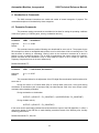
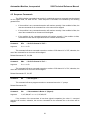
1.2 Digital I/O Interface
The S200 includes 4 channels of general purpose digital input and 4 channels of general purpose
digital output. Additionally, there are four channels of dedicated digital input for each of the two axis'. All
of these I/O are protected through the use of optoisolators.
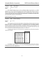
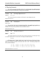
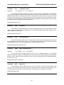
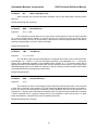
1.2.1 Dedicated Digital Inputs
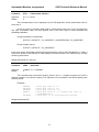
Figure 1 illustrates one of the S200’s dedicated digital inputs. These inputs are Limit+, Limit-,
Home and Fault for both axis of the S200. The power to activate these inputs is provided by the S200 so
it is only necessary to complete the circuit to activate the input.
The Limit inputs are intended for signaling the S200 that an axis has reached it’s end of travel.
When such an event occurs, the S200 can ignore the event or stop the servo in some controlled fashion.
The Home input is for detecting some sort of "home position" sensor. This can be used with the encoder
index input to implement a very accurate homing method. A typical use for the Fault input is for an
external device to signal a fault condition such as over-temperature.
Note: The external Fault input is tied to the internal over-temperature signal from the onboard drivers.
When a fault condition occurs, that is either the internal over-temperature signal or external Fault
signal go active, the 16-bit internal variable FCNT (see Internal Variables) begins to increment at 1
rate of once per millisecond. If the fault condition clears then the FCNT variable is also cleared. If
the fault condition remains present long enough for the FCNT variable to count up to the value
assigned to the FCMP variable, then the over Fault bit in the status word will be set and the servo
will be disabled (assuming the Fault interrupt has not been enabled). The default value for FCMP
is 10000 which will give a 10 second delay before causing the Fault bit to be set.
Figure 1. S200 Dedicated Input.
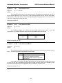
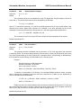
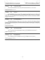
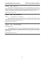
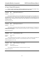
1.2.2 General Purpose Inputs
Figure 2 illustrates one of the S200’s general purpose inputs. These inputs are galvanically
isolated from the S200. Current of the proper polarity must be supplied to the circuit to activate the input.
8
Automation Modules, Incorporated
S200 Technical Reference Manual
Figure 2. S200 General Purpose Inputs
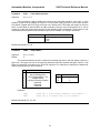
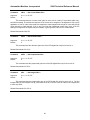
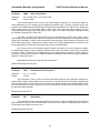
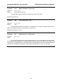
1.2.3 General Purpose Outputs
Figure 3 illustrates one of the S200’s general purpose outputs. These outputs are galvanically
isolated from the S200. When an output is activated, positive current will flow from the collector of the
optocoupler transistor (the output pin) to it’s emitter (the output return pin),
Figure 3. S200 General Purpose Output
1.2.4 Digital I/O "States"
There are several commands that deal with controlling the digital I/O. All of these commands
operate based on the following philosophy: With regard to an input, "active" means there is sufficient
current flowing through that input and "inactive" means there is lack of sufficient current through that
input. With regard to outputs, "active" means the ability for an output to pass current and "inactive" means
the inability for an output to pass current.
The Channel High (CH) and Channel Low (CL) commands provide the user with the ability to
determine whether a channel is active in the "on" state (CH) or active in the "off" state (CL). This is
analogous to a switch and to whether it is normally open or normally closed. The Channel On (CN) and
Channel Off (CF) commands do exactly as they imply in that they will turn a given output either on or off,
which will make that output either active or inactive depending on the CH and CL commands as stated
previously.
The (CH) command causes the following interpretation of the inputs and outputs:
•
•
•
•
An "activated" output is considered to be ON (e.g., Channel On “CN” command).
An "inactivated" output is considered to be OFF (e.g., Channel Off “CF” command).
An "activated" input is considered to be ON (e.g., Do If On “DN” command).
An "inactivated" input is considered to be OFF (e.g., Do If Off “DF” command).
9
Automation Modules, Incorporated
S200 Technical Reference Manual
The (CL) command causes the following interpretation of the inputs and outputs:
•
•
•
•
An "activated" output is considered to be OFF (e.g., Channel Off “CF” command).
An "inactivated" output is considered to be ON (e.g., Channel On “CN” command).
An "activated" input is considered to be OFF (e.g., Do If Off “DF” command).
An "inactivated" input is considered to be ON (e.g., Do If On “DN” command).
Input Current
Flowing
No Flow
“CH”
On
Off
“CL”
Off
On
Output Current
Flowing
No Flow
“CH”
CN
CF
“CL”
CF
CN
Table 2. I/O States.
Another feature of the digital input system is the ability for software input debouncing. All of the
general purpose digital inputs are automatically sampled once every millisecond. Depending on the
debounce delay set by the Input Debounce (ID) command, a given input must remain in the same state
during one or more samplings before it is considered valid. If an input were to be found in a changed
state during a sampling, the input would become invalid and the debounce delay would be restarted. If no
or "0" debounce delay is used, then no input debouncing is performed. For example: if a "ID5" command
has been issued, then a given input must remain in the same state for 5 samplings or for 5 milliseconds.
1.2.5 I/O Technical Specifications
1.2.5.1 General Purpose I/O Nominal Specifications.
5
0.83
24
4.87
1.1
6
40
100
Unit
V
mA
V
mA
V
V
V
mA
Specification
Minimum voltage to activate input.
Input current at minimum activation voltage.
Maximum input voltage.
Input current at maximum voltage.
Maximum voltage to deactivate input.
Absolute maximum reverse input voltage.
Maximum voltage output can sustain.
Maximum current output can sustain.
Table 3: General Purpose I/O Specifications
1.2.5.2 Dedicated I/O Nominal Specifications.
10
1
Unit
Ω
KΩ
Specification
Maximum external circuit resistance to activate input.
Minimum external circuit resistance to deactivate input.
10
Automation Modules, Incorporated
S200 Technical Reference Manual
Table 4: Dedicated I/O Specifications
1.3 Encoder Interface
The S200 has two channels of quadrature type encoder interface with optional index signal input
and the ability to supply +5 VDC at a minimum of 50 mA (or greater depending on other demands put on
the internal 5 VDC power supply). The phase A+ and phase B+ inputs are pulled up to +5 VDC with 2.7K
resistors, and the phase A- and phase B- inputs a biased at +2.5 VDC with 2.7K resistors. This
arrangement which will accommodate both open collector and totem pole single-ended output encoders
or differential output encoders. The phasing of the channels as well as the index signal sense can be
changed via program command.
1.4 Output Driver Interface
The S200 onboard output drivers are PWM switching amplifiers capable of supplying 3 Amps
continuous and 6 Amps peak (for 200 mS minimum) at a switching frequency of approximately 19.531
KHz. These drivers are intended for driving DC brush type motors or actuators. Both drivers share the
main power supply input and the peak voltage output to the motor will be nearly that of what is supplied.
The output drivers include an over-temperature sensor. If this sensor determines that the
amplifier’s temperature is greater than 140° C, the amplifier will then be disabled and the OverTemperature bit will be set in that axis' status word.
For applications requiring capabilities above those of the onboard drivers, the ability to interface
to external drivers is provided. This consists a 12-bit D/A ±10 VDC analog output signal for each axis. In
applications where external drivers are not required, the analog outputs can be used for other purposes
(e.g.,: oscilloscope monitoring of following error or output command).
1.5 Analog to Digital Conversion (A/D) Interface
The S200 provides a 5 channel, 10 bit A/D conversion interface with a +10 VDC reference and
analog ground. For reverse compatibility purposes the A/D interface is actually ten channels but
the user is only given access to channels 0, 1 and 2 while channels 6 and 7 are used internally for
monitoring the output current of the onboard drivers. The other channels are unavailable and
should be ignored.
Whenever a Tell Analog "TA" or Get Analog "GA" command is issued, the specified A/D channel
is converted and the result is either reported or stored for access by the user. Also, whenever the servo
loop for an axis is executed, the "current monitoring" channel for that axis is converted and the result is
stored for later access.
1.6 Serial Interface
The S200 communicates with a host computer or a "dumb" terminal via an RS-232 serial
interface. The baud rate is user selectable from 300 to 19,200 baud with 9600 baud being the default.
Characters are fixed at 8 bits in length with 1 stop bit and no parity. Software XON / XOFF handshaking is
provided. Hardware handshaking is not supported at this time.
11
Automation Modules, Incorporated
S200 Technical Reference Manual
2. Macro Interrupt System
The S200 employs a "Macro Interrupt System" to provide additional versatility in programming the
S200. This system comprises 32 interrupt sources with corresponding vectors. When an interrupt's
source is enabled for operation and then becomes active, the current macro being executed is saved to a
so called macro stack and execution of the macro specified by that interrupt's vector table entry begins.
This happens to be similar procedure to that which the Macro Call (MC) command follows.
2.1 The Interrupt Vector Table
The Interrupt Vector Table consists of an entry for each interrupt source and each entry will
correspond to that interrupt's level (level 0 = entry 0, level 1 = entry 1, etc.). A particular table entry must
be loaded with the number of a valid macro to be executed should that interrupt source become active.
The method for loading a vector table entry is provided by the Load Vector (LV) command. The user must
first use the Accumulator Load (AL) command to set the number of the macro for a vector. The LV
command is then used to transfer the low 8-bits of the accumulator to the vector table entry specified by
the LV command. If an interrupt is generated and that vector table entry has not been defined (equal to 0)
then the interrupt will not be executed. Note that this implies that macro "0" cannot be used as an
interrupt macro. If an interrupt is generated and it's vector table entry has been defined but the macro it
specifies has not, then an error will be reported.
2.2 Enabling and Disabling Interrupts
Loading a vector table entry will not enable an interrupt for operation. The Enable Vector
(EV) command must be used for this purpose. When the EV command is used, it will enable the interrupt
source (specified with the command) to function. In the event that it is necessary to disable an interrupt
source, there is a Disable Vector (DV) command that functions in a similar manner as the EV command.
In order to prevent multiple or continuous interrupts, as an interrupt is taken it is automatically
disabled. This means that the user must re-enable that interrupt using the EV command before it will
occur again.
13
Automation Modules, Incorporated
S200 Technical Reference Manual
2.3 Interrupt Sources
The following table lists all the possible interrupt sources.
Interrupt Source
Axis 0 Error
Axis 1 Error
Reserved
Reserved
Axis 0 Fault
Axis 1 Fault
Reserved
Reserved
Axis 0 Limit
Axis 1 Limit
Reserved
Reserved
Axis 0 IP/IR
Axis 1 IP/IR
Reserved
Reserved
Level / Vector
31
30
29
28
27
26
25
24
23
22
21
20
19
18
17
16
Interrupt Source
Reserved
Reserved
Reserved
Reserved
Reserved
Reserved
Reserved
Reserved
Reserved
Reserved
Reserved
Reserved
Digital Input 3
Digital Input 2
Digital Input 1
Digital Input 0
Level/Vector
15
14
13
12
11
10
9
8
7
6
5
4
3
2
1
0
Table 5. Macro Interrupt Sources.
The Axis Error interrupts indicate that the position following error for a given axis has exceeded
the limit set by the Set Error (SE) command. Normally, when this limit is exceeded, the servo is disabled
and the "Error" bit in that axis' status word is set. If the interrupt for this condition is enabled, the
"Error" bit will still be set but the servo will not be disabled.
The Axis Fault interrupts indicate that a fault condition (usually an over-temperature condition)
has arisen. Normally, when this condition is detected, the servo is disabled and the "Fault" bit in that axis'
status word is set. If the interrupt for this condition is enabled, the "Fault" bit will still be set but the
servo will not be disabled.
The Axis Limit interrupts indicate that either a Limit+ or Limit- condition for an axis has been
detected. Whether or not a limit input will be recognized is determined by the Limit On (LN) and Limit Off
(LF) commands. The action taken is determined by the Limit Mode (LM) command.
Digital Inputs 00 - 03 provide 4 levels of undedicated, user definable interrupts. The interrupt for a
given input will be active when that input is active.
2.4 Interrupt Priority
If more than one interrupt source becomes active at the same time, then the source with the
higher level will be executed first. Level/vector 31 has the highest priority and level/vector 0 has the
lowest priority.
14
Automation Modules, Incorporated
S200 Technical Reference Manual
2.5 Interrupt Completion
Once an interrupt macro (or set of macros) has finished executing, a Return from Call (RC)
command or an undefined macro may be used to cause a return from the interrupting macro back to the
interrupted macro where command execution will continue from where it was interrupted (see MS
command). In cases where it is undesirable to return to the interrupted macro, the Unpush Macro (UM)
command can be used to remove the previously pushed macro from the macro stack. This command can
also be used to completely reset the macro stack in order that the user program can be restarted.
2.6 Interrupt Latency
Interrupt sources are sampled before each command in a macro is executed. This means that
the amount of time that an interrupt is held off before execution (also known as interrupt latency) depends
on how long it takes the previous command to complete. For most commands this delay will be
imperceptible.
Commands such as Wait (WA), Wait for Edge (WE), Wait for Stop (WS), Wait for Off (WF), Wait
for On (WN) and Wait for Index (WI) would normally be a source of unacceptable delay in that they can
quite often be indeterminate in length. This problem has been avoided by making these instructions
interruptable. For example, if a WA10000 command (a 10 second delay) is currently in progress and an
interrupt comes along, the remaining delay period will be saved and then returned to after the interrupt
has completed. If the interrupt were to take 3 seconds to execute, then the total wait time of the WA10000
command would be extended to 13 seconds.
The Position Mode (PM), Torque Mode (QM), Velocity Mode (VM), Wait for Position Absolute
(WP) and Wait for Position Relative (WR) commands and any command that uses the serial
communications link are all commands that could cause unacceptable interrupt latency. Therefore, their
usage should be carefully considered where interrupts are possible.
15
Automation Modules, Incorporated
S200 Technical Reference Manual
3. Entering Commands
Immediately after power-up, the S200 is ready to accept commands. To verify this, you can hit
the ESC key. If everything is working properly, this should cause a greater than sign (">") prompt to
appear on your display. If not, you need to verify that the power and communications connections are
correct and verify the compatibility of the communications protocol.
Commands are entered via a "dumb" terminal or host computer such as a PC compatible.
Commands sent to the S200 should consist of standard ASCII characters, and the command lines should
be followed by a carriage return. Linefeeds are not necessary since they are used for formatting and
therefore they are ignored. As characters are entered at the keyboard, they should be echoed on your
display. If your display echoes its own transmitted characters, you will want to issue the Echo Off (EF)
command; otherwise, the Echo On (EN) command (which is the default mode) should be issued. If you
enter an invalid command, the S200 will respond with a question mark "?" followed by a code indicating
the type of error and the Status LED will begin to blink. These codes are listed in Appendix A, S200 Error
Code Definitions.
If you make a mistake when entering a command, you can backspace to correct the error. If you
are entering commands and change your mind, hitting the ESC key will cancel the line and give a new ">"
prompt.
Once a command line has been entered and has finished executing, hitting the RETURN key
will cause the same command line to be re-executed. While a set of commands are executing, hitting
the space bar will cause command execution to pause until the space bar is hit again. Also, if the ESC
key is hit during execution or pause, command execution will be terminated, and you will receive a
new ">" prompt.
Command instructions are intended for use with the following syntax:
[Axis#]Command[Argument]<CR>
or...
[Axis#]Command[Argument],[Axis#]Command[Argument],...etc.
The axis number is normally specified as being from "1" to "2" with "0" being used to refer to both
axis' at the same time. Once an axis has been specified, the same one will remain in effect until another
is specified. For example, if the following were entered:
1SG100,SD500,SV1000000<CR>
or...
1SG100<CR>
SD500<CR>
SV1000000<CR>
the SG command specifies the axis number, so the subsequent SD and SV commands are performed on
the same axis. If the following command were issued:
0TP<CR>
it would have the same affect as issuing these commands:
1TP<CR>
17
Automation Modules, Incorporated
S200 Technical Reference Manual
2TP<CR>
During interrupts and macro calls, the axis number is saved and then later restored. After an
interrupt macro entered or a macro call is taken, it is a good idea for the user to make sure an axis
number (if necessary) gets set during one of the first commands encountered.
The numerical range of an argument will vary depending on the command with which it is used.
The mathematical interpretation of the argument will depend on whether the Decimal Mode (DM) or
Hexadecimal Mode (HM) was the last issued (DM is the power on default). Both decimal and
hexadecimal numbers less than zero should be entered with a preceding minus "-" sign. If no argument is
given, then it will be assumed as "0". The exceptions to this are the Macro Define (MD), Macro Jump
(MJ), Macro Call (MC),Macro Sequence (MS), Reset Macro (RM) and Tell Macro (TM), commands. It
should be noted that commands can be strung together by using commas, up to a maximum line length
of 127 characters.
If a command line is ended by a ";" and a comment, i.e...
>SG1000,SD5000 ; Set filter gains.<CR>
then the ";" and anything following it to the end of the line will be ignored. This feature is not particularly
useful if you are entering commands manually, as comments are not retained by the S200. However, if
commands are downloaded to the S200 from a host computer, the ability for line comments can make
program documentation possible and desirable.
3.1 Downloading Commands
In many cases, it is more convenient to enter commands using a text editor on a host computer
and then download that text file to the S200 using a communications program such as ProComm® or the
Microsoft® Windows™ Terminal program. Whatever communications software is used, it must have the
ability to provide a short delay (approx. 100 mS) after transmitting each line to give the S200 time to
interpret and store the commands that were just sent.
18
Automation Modules, Incorporated
S200 Technical Reference Manual
4. Introduction to Commands
The S200 command instructions are varied and consist of several categories of purpose. The
command descriptions will be detailed by these categories.
4.1 Parameter Commands
The parameter setting commands are considered to be those for setting the operating conditions
of the servo system (i.e. PID filter gains, velocity, acceleration and etc.).
Command:
aDBn -- Dead-Band --
Argument:
Default:
0 <= n <= 16383
0
This command sets the position following error dead-band for servo axis 'a'. The purpose for the
DB command is to allow an acceptable static position error for which there will be no restoring force. This
has the affect of reducing or eliminating "hunting" which is the continuous movement at or about a
position in trying to seek that position. This is useful for applications that cannot tolerate this condition.
Please note that the DB command is only in effect when the servo is not in motion (or when the
Trajectory Complete bit is set in the servo status word).
Related Commands: TF
Command:
aFAn
-- Feed-forward, Acceleration --
Argument:
Default:
0 <= n <= 32767
0
This command allows for the adjustment of the PID digital filter acceleration feed-forward term for
servo axis 'a'.
During the course of a Position Mode (PM) or Velocity Mode (VM) move, at any point during
acceleration or deceleration (with a consistent load), the ideal required value of the servo output is fairly
consistent and somewhat predictable.
During acceleration or deceleration:
OUTPUT = (VELOCITY * FV_CONSTANT) + (ACCELERATION * FA_CONSTANT)
During constant velocity:
OUTPUT = (VELOCITY * FV_CONSTANT)
If this value can be dynamically predicted and summed with the output of the PID digital filter, in effect, it
reduces the burden of the PID filter to make lead/lag corrections based of the following error, thereby
enhancing performance.
Related Commands: FV, OM, OO
19
Automation Modules, Incorporated
Command:
FF
Default:
Off
S200 Technical Reference Manual
-- Fail Input Off --
This command has no effect but is retained for backward compatibility purposes.
Command:
FN -- Fail Input On --
Default:
Off
This command has no effect but is retained for backward compatibility purposes.
Command:
aFRn
-- Set Derivative Sampling Period --
Argument:
Default:
0 <= n <= 127
0
This command allows for the adjustment of the derivative sampling interval for servo axis 'a'. The
period of this interval can be calculated by the following:
T = (n+1) * S * 0.000100
where "T" is the period in seconds, "n" is the FR command argument and "S" is the sample period count
specified by the Servo Speed (SS) command. For example, if the value previously set by the SS
command is 10 and the value set by the FR command is 1, then the derivative sample period will be:
(1+1) * 10 * 0.000100 = .002000 S or 2 mS
This command is useful in tuning the PID servo loop to the inertial properties of the system.
Related Commands: RI, SS
20
Automation Modules, Incorporated
Command:
aFVn
Argument:
Default:
0 <= n <= 32767
0
S200 Technical Reference Manual
-- Feed-forward, Velocity --
This command allows for the adjustment of the PID digital filter velocity feed-forward term for
servo axis 'a'.
During the course of a Position Mode (PM) or Velocity Mode (VM) move, at any point along the
way (with a consistent load), the ideal required value of the servo output is fairly consistent and
somewhat predictable.
During acceleration or deceleration:
OUTPUT = (VELOCITY * FV_CONSTANT) + (ACCELERATION * FA_CONSTANT)
During constant velocity:
OUTPUT = (VELOCITY * FV_CONSTANT)
If this value can be dynamically predicted and summed with the output of the PID digital filter, in effect, it
reduces the burden of the PID filter to make lead/lag corrections based of the following error, thereby
enhancing performance.
Related Commands: FA, OM, OO
Command:
aGRn -- Gear Ratio --
Argument:
Default:
-8388607 <= n <= 8388607
0
This command sets the electronic gearing ratio for axis 'n'. A negative argument will cause a
direction reversal in the electronic gearing. The argument to this command is the desired gearing ratio
scaled by 65536.
Examples:
GR65536
GR131072
GR32768
GR6554
GR-65536
;
;
;
;
;
;
Slave gear ratio is 1:1
Slave gear ratio is 2:1
Slave gear ratio is .5:1
Slave gear ratio is .1:1 (actual gear ratio is
.100006103516:1).
Slave ratio is 1:1 with direction reversal
Related Commands: EG
21
Automation Modules, Incorporated
Command:
aILn
Argument:
Default:
0 <= n <= 16,383
0
S200 Technical Reference Manual
-- Set Integration Limit --
This command clamps the level of influence that the PID digital filter integral term can use to
reduce the static position error of servo axis 'a'. When properly adjusted, this can enhance loop stability
and operation. The Integral Limit (IL) and Set Integral Gain (SI) must both be set to a non-zero value in
order for the integral term to have any effect.
Related Commands: SI
Command:
aLFn
-- Limit Switch Input Off --
Argument:
Default:
0 <= n <= 3
0
This command disables one or more of the limit switch inputs for servo axis 'a'. The valid
arguments to this command determine which inputs will be disabled and are as follows:
n
0, 3 or no argument
1
2
Limit Switch Inputs Disabled
Limit+ and LimitLimit+
Limit-
Related Commands: LM, LN
Command:
aLMn -- Limit Switch Input Mode --
Argument:
Default:
0 <= n <= 3
0
This command is used to select how the S200 will react when a limit switch is activated for servo
axis 'a'. The valid arguments for this command are as follows:
n
0
1
2
3
Action
Turn servo off, continue commands
Stop abruptly, continue commands
Decelerate smoothly, continue commands
Interrupt only
In all cases, the Error flag in the status word will be set. This will prevent the S200 from moving
the servo until the flag is cleared by issuing the Motor On (MN) command. Before this command will have
any effect, the limit switch must be enabled with the Limit Switch On command (LN).
Related Commands: LF, LN
22
Automation Modules, Incorporated
Command:
aLNn
Argument:
0 <= n <= 3
S200 Technical Reference Manual
-- Limit Switch Input On --
This command is used to enable one or both of the limit switch inputs for servo axis ‘a’. Once
enabled, the servo will be stopped or turned off if a limit switch input goes active. At the same time the
Limit Switch Tripped and Error Flags will be set in the status word. These flags will remain set until the
servo is turned back on with the Motor On (MN) command. Once the servo is turned back on, it can be
moved out of the limit switch region with any of the standard motion commands. The argument to this
command determines which of the limit switch inputs will be enabled. The coding is as follows:
n
0,3 or no argument
1
2
Limit Switch Inputs Enabled
Limit+ and LimitLimit+
Limit-
Related Commands: LF, LM
Command:
aOMn -- Output Mode --
Argument:
Default:
0 <= n <= 255
0
This command allows the user to determine what data gets sent to the D/A analog output for a
given axis. The upper four bits of the argument determine what D/A channel data gets output to. This
allows for redirection of the data to any of the D/A channels. If no redirection is specified, the default D/A
channel selected is that of the current axis.
‘n’
0
1
2
3
4
5
6
7
Value Output
Servo Output Command
Servo Following Error
Servo Following Error * 64
Variable USER1
Low Bits of Encoder Position
Reserved
Reserved
Reserved
‘n+’
0
16
32
Redirect Channel
Default
1
2
Examples:
1OM0
2OM9
; Send axis 1 servo output command to D/A channel 1.
; Send axis 2 following error to D/A channel 1.
Related Commands: FA, FV, OO
23
Automation Modules, Incorporated
Command:
aOOn -- Output Offset --
Argument:
Default:
-32767 <= n <= 32767
0
S200 Technical Reference Manual
This command allows the user to set a continuous output for servo axis ‘a’. In certain
applications, such as an overhanging load, there will be a continuous burden placed upon a servo axis. In
cases like these, where there is a predictable load, the OO command can be used to provide a
continuous restoring force that will be combined with the output of the PID digital filter. This has the affect
of improving the performance of the PID digital filter in that because it is not saturated with static load, it
has a better dynamic response to load disturbances.
Related Commands: FA, FV, OM
Command:
aPHn
-- Set Servo Phasing --
Argument:
Default:
0 <= n <= 63
0
This command is used to set the output polarity, encoder phasing, Index input sense, Home input
sense, Limit+ and Limit- input sense for servo axis ‘a’. The polarity of the output will determine whether
the servo is driven in a direction that reduces or increases position error. The encoder phase will
determine whether the position count will increase or decrease for a valid encoder input sequence. The
Index sense determines what logic edge will cause the Index input to be active. The Limit+, Limit- and
Home sense determines whether these signals are active “on” or active “off.
To determine the argument to be used with the PH command, use the follow table and add the
required values together.
Output Phase Normal
Output Phase Reversed
Encoder Phase Normal
Encoder Phase Reversed
Index Active Level Low
Index Active Level High
Home Sense Active "ON"
Home Sense Active "OFF"
Limit+ Sense Active "ON"
Limit+ Sense Active "OFF"
Limit- Sense Active "ON"
Limit- Sense Active "OFF"
Add to 'n'
0
1
0
2
0
4
0
8
0
16
0
32
For example, if it were necessary to reverse the encoder phasing and to set the Limit+ and Limitinputs to active "OFF", then 'n' would be (2 + 16 + 32) or 50. The default phasing and sense is equivalent
to issuing this command with a argument of 0.
24
Automation Modules, Incorporated
Command:
aRIn
Argument:
Default:
0 <= n <= 127
0
S200 Technical Reference Manual
-- Sampling Rate of Integral --
This command allows for the adjustment of the PID digital filter integral sampling interval for
servo axis 'a'. The period of this interval can be calculated by the following:
T = (n+1) * S * 0.000100
where "T" is the period in seconds, "n" is the RI command argument and "S" is the sample period count
specified by the Servo Speed (SS) command. For example, if the value previously set by the SS
command is 10 and the value set by the RI command is 1, then the integral sample period will be:
(1+1) * 10 * 0.000100 = .002000 S or 2 mS
This command is useful in tuning the PID servo loop to the inertial properties of the system.
Related Commands: FR
Command:
aSAn
-- Set Acceleration --
Argument:
Default:
0 <= n < 1,073,741,823
0
This command sets the acceleration rate for servo axis 'a'. The 32 bit argument to this command
is scaled by 65536. This number determines how much the servo's velocity will be altered by each servo
loop interval (determined by the Servo Speed "SS" command) while it is accelerating or decelerating. If
this command is executed during a Position Mode move, it will be ignored.
Example:
Encoder: 500 lines or 2000 Counts/Rev
Desired Acceleration: 75 Rev/Sec²
Servo Loop Interval: 1,000 Hz
9830.4 = ((75 Rev/Sec * 2000 Counts/Rev) / 1000 Hz²) * 65536
To achieve an acceleration of 75 Rev/Sec², the command SA9830 would be issued. A simpler
way to calculate the acceleration argument would be to determine a constant for your application by
which to calculate desired acceleration.
131.072 = K = ((1 Rev/Sec * 2000 Counts/Rev) / 1000 Hz²) * 65536
9830.4 = 75 Rev/Sec * K
Please note that if the Set Acceleration (SA) command is used with an argument of "0", then you
have commanded the velocity to change in steps of zero which means if the servo is stopped it will not be
able to move, and if the servo is moving it will not be able to change velocity.
Related Commands: SS, SV
25
Automation Modules, Incorporated
Command:
aSCn
Argument:
Default:
0 <= n <= 32,767
0
S200 Technical Reference Manual
-- Set Current Mode Gain --
This command sets the "current mode" gain for servo axis 'a' used by Torque Mode (QM1 only,
see QM command). This allows the response of the current error integrator to be adjusted to suit a given
application. A low SC value will provide slow response to load changes while a high SC value will provide
quick response to load changes. If SC is set is too low then inadequate control may occur. If the SC
setting is too high then the system may be unstable. A good "general" value for SC is about 8000.
Related Commands: QM, SQ
Command:
aSDn
-- Set Derivative Gain --
Argument:
Default:
0 <= n <= 32,767
0
This command sets the derivative gain term of the PID digital filter loop for servo axis 'a'.
Related Commands: SG, SI, IL
Command:
aSGn -- Set Proportional Gain --
Argument:
Default:
0 <= n <= 32,767
0
This command sets the proportional gain term of the PID digital filter loop for servo axis 'a'.
Related Commands: SI, SD, IL
Command:
aSIn
-- Set Integral Gain --
Argument:
Default:
0 <= n <= 32,767
0
This command sets the integral gain term of the PID digital filter loop for servo axis 'a'. The Set
Integral Gain (SI) and Integral Limit (IL) must both be set to a non-zero value in order for the integral term
to have any effect.
Related Commands: SG, SD, IL
26
Automation Modules, Incorporated
S200 Technical Reference Manual
Command:
aSQn -- Set [Maximum] Torque Level --
Argument:
-32,767 <= n <= 32,767 in Torque Mode 0 (QM0)
-1,023 <= n <= 1,023 in Torque Mode 1 (QM1)
0 <= n <= 32,767 in Position Mode (PM)
0 <= n <= 32,767 in Velocity Mode (VM)
32,767
Default:
For servo axis 'a', this command sets the maximum output level when in Position Mode (PM) or
Velocity Mode (VM) and sets the desired output level when in Torque Mode (QM). When this command is
issued in Position Mode (PM) or Velocity Mode (VM), its limiting effect will remain, in all modes of
operation, until again changed. Note that an argument less than zero is allowed only in Torque Mode
(QM).
Examples:
>PM,SQ20000<CR>
; Set maximum output to +-20000.
>VM,SQ10000<CR>
; Set maximum output to +-10000.
>QM,SQ20000<CR>
; Set output to forward 20000.
>QM,SQ-10000<CR>
; Set output reverse 10000.
>PM,SQ10000<CR>
>QM0,SQ15000<CR>
;
;
;
;
Set maximum output to +-10000.
Set output to forward 15000 but
will only achieve output of 10000
due to previous command.
Related Commands: PM, QM, SC, VM
27
Automation Modules, Incorporated
Command:
SSn
Argument:
Default:
1 <= n <= 255
2
S200 Technical Reference Manual
-- Set Servo Speed --
This command sets the servo loop interval, which is the same for both axis' of the S200. The
period of this interval can be calculated by the following:
T = (n) * 0.000100
where "T" is the period in seconds and "n" is the SS command argument. For example, if the value set
by the SS command is 10 then the servo loop period will be:
10 * 0.000100 = .001000 S or 1 mS
The minimum servo loop rate is 100 µS per enabled axis. The following table shows the minimum
servo loop times:
# Axis
Enabled
0
1
2
Minimum Loop Time
100µS
100µS
200µS
Using the SS command affects the Set Velocity (SV) and Set Acceleration (SA) commands in
that they both are specified in terms of servo loop intervals. For example, if the servo loop rate is doubled,
the velocity and acceleration would appear to have been halved. It should also be noted that the "SS"
command will most likely affect the required settings of the PID digital filter.
Related Commands: SA, SV
28
Automation Modules, Incorporated
Command:
aSVn
Argument:
Default:
0 <= n < 1,073,741,823
0
S200 Technical Reference Manual
-- Set Maximum Velocity --
This command sets the desired velocity (in quadrature counts per servo loop interval) for servo
axis 'a'. The 32 bit argument to this command consists of a 16 bit integer part and a 16 bit fractional part.
Example:
Encoder: 500 lines, 2000 Counts/Rev
Desired Velocity: 40 Rev/Sec
Servo Loop Interval: 1,000 Hz
5242880 = ((40 Rev/Sec * 2000 Counts/Rev) / 1000 Hz) * 65536
To achieve a velocity of 40 Rev/Sec, the command SV5242880 would be issued. A simpler way
to calculate the velocity would be to determine a constant for your application by which to calculate
desired velocity.
131072 = K = ((1 Rev/Sec * 2000 Counts/Rev) / 1000 Hz) * 65536
5242880 = 40 Rev/Sec * K
Related Commands: SA, SS
29
Automation Modules, Incorporated
S200 Technical Reference Manual
4.2 Reporting Commands
The reporting commands output data relevant to the operating status of the S200. Numerical
output will be in the mathematical base determined by the Decimal Mode (DM) / Hexadecimal Mode (HM)
commands and output will be followed by a carriage return and linefeed.
Command:
TAn
-- Tell Analog to Digital Channel 'n' --
Argument:
0 <= n <= 9
This command will cause a conversion on A/D channel 'n' and will display the result.
Related Commands: GA
Command:
aTB
-- Tell Breakpoint --
Default: "None"
This command reports the last programmed breakpoint value specified by the Interrupt on
Position Absolute (IP) or the Interrupt on Position Relative (IR) commands for servo axis 'a'. If no
breakpoint value has yet been specified then the word "NONE is returned.
Related Commands: IP, IR
Command:
TCn
-- Tell State of I/O Channel 'n' --
Argument:
Default:
0 <= n <= 63
"Off"
This command reports the current state of the I/O channel specified by 'n' and what type of logic
the channel is (either active "on" or active "off"). The display is formatted as follows:
/xx = aaa
The presence of the "/" character indicates that a channel is active in the "off" state. A lack of the
"/" character indicates that the channel is active in the "on" state. The "xx" indicates the channel number
and the "aaa" indicates the channel's current state, either "ON" or "OFF". The following examples show
all the possible combinations:
01
/01
01
/01
=
=
=
=
ON
ON
OFF
OFF
;
;
;
;
Channel
Channel
Channel
Channel
1
1
1
1
is
is
is
is
"ON" in the active "ON” state.
"ON" in the active "OFF" state.
"OFF" in the active "ON" state.
"OFF" in the active "OFF" state.
Related Commands: CF, CH, CL, CN
30
Automation Modules, Incorporated
Command:
aTD
S200 Technical Reference Manual
-- Tell Derivative Gain --
This command reports the derivative gain value of the PID digital filter for servo axis 'a'.
Related Commands: TG, TI, TL
Command:
TE
-- Tell Error --
This command reports the last error code caused by any command or macro. If no error has
occurred then a "0" will be reported. Once the TE command has been issued, then the error code will be
reset to zero. The TE command is useful for determining what error occurred in the case that no display
was connected at the time.
Command:
aTF
-- Tell Following Error --
This command reports the following error for servo axis 'a'. This value is the difference between
the current desired temporal position (or that which is reported by the Tell Optimal (TO) command) of the
trajectory generator and the servo's current real position (or that which is reported by the Tell Position
(TP) command).
Related Commands: DB
Command:
aTG
-- Tell Proportional Gain --
This command reports the proportional gain value of the PID digital filter for servo axis 'a'.
Related Commands: TI, TD, TL
Command:
aTI
-- Tell Integral Gain --
This command reports the integral gain value of the PID digital filter for servo axis 'a'.
Related Commands: TG, TD, IL
31
Automation Modules, Incorporated
Command:
aTKn
Argument:
0 <= n <= 1
S200 Technical Reference Manual
-- Tell (K) Constants --
This command will display a number of internal settings depending on the value specified by 'n'. If
'n' is "0" or is not specified, then various parametric values for the servo axis specified by 'a' will be
displayed. If 'n' is "1", then various system parameters will be displayed.
Example display for the command "1TK0":
>1TK0
Parameter Values for Axis [1]
Proportional Gain ---------Integral Gain -------------Derivative Gain -----------Integral Limit ------------Current Gain --------------Velocity Feed-forward Gain Accel. Feed-forward Gain --Output Offset -------------Position Error Dead-Band --Maximum Following Error ---Integral Sample Rate ------Derivative Sample Rate ----Phase and Sense Settings --Maximum Velocity ----------Acceleration --------------Desired Direction ---------Torque (output) Limit -----Axis Type ------------------
(SG)
(SI)
(SD)
(IL)
(SC)
(FV)
(FA)
(OO)
(DB)
(SE)
(RI)
(FR)
(PH)
(SV)
(SA)
(DI)
(SQ)
(OM)
=
=
=
=
=
=
=
=
=
=
=
=
=
=
=
=
=
=
0
0
0
0
0
0
0
0
0
16383
0
0
0
0
0
0
32767
0
Example display for the command "TK1":
>TK1
System Parameter Settings (group 1).
Axis 1 Enabled ------------- (EA)
Axis 2 Enabled ------------- (EA)
Base 16 Input & Output -- (HM/DM)
Character Echo ---------- (EN/EF)
Handshake --------------- (HN/HF)
Fail -------------------- (FN/FF)
Servo Loop Rate ------------ (SS)
Input Debounce/Delay ------- (ID)
Phase and Sense Settings --- (CV)
Intr. Vector Enable, HIGH (EV/DV)
Intr. Vector Enable, LOW (EV/DV)
Firmware Revision ---------- (VE)
32
=
=
=
=
=
=
=
=
=
=
=
=
Yes
Yes
Off
On
Off
Off
2
0
0
0
0
3.10
Automation Modules, Incorporated
Command:
aTL
S200 Technical Reference Manual
-- Tell Integration Limit --
This command reports the integration limit value of the PID digital filter for servo axis 'a'.
Related Commands: TG, TI, TD
Command:
TMn
-- Tell Macros --
Argument:
-2 <= n <= 255
The Tell Macro (TM) command will display the commands which make up any macros that have
been defined. If 'n' >= 0 and 'n' <= 255, then the macro specified by 'n' be displayed. If 'n' = -1, then all the
macros will be displayed preceded by the individual macro number. If 'n' =-2, then all macros will be
displayed and will be preceded by the letters "MD" and the individual macro number. This is useful when
downloading programs from the S200 to a computer in that you need not re-enter the Macro Define (MD)
command and number at the beginning of each macro.
Related Commands: MD, RM
Command:
aTO
-- Tell Optimal Position --
This command reports the desired position for servo axis 'a'. This value may be different from the
position reported by the TP command if the servo is moving or the controller is unable to drive the servo.
Related Commands: TT, TP
Command:
aTP
- Tell Real Position --
This command reports the absolute position of servo axis 'a'. It may be used to monitor motion
during both the Motor On (MN) and the Motor Off (MF) states.
Related Commands: TT, TO
Command:
aTQ
-- Tell Torque --
his command reports the current output torque being commanded for servo axis 'a'. This value
will be either that which is generated by the PID output or which is set by the user via the Torque Mode
(QM).
Command:
TRn
-- Tell Contents of Register 'n' --
Argument:
0 <= n <= 511
This command reports the value contained by Register 'n'.
Related Commands: Register Commands
33
Automation Modules, Incorporated
Command:
aTS
S200 Technical Reference Manual
-- Tell Status Word --
This command reports the operating status word of servo axis 'a'. The response is coded into a
single 32 bit value. The meaning of each bit is listed below:
Bit
0
1
2
3
4
5
6
7
8
9
10
11
12
13
14
15
16
17
18
19
Purpose
Servo Enabled. This bit will be set to “1” when the servo is enabled via
the Motor On (MN) command. A “0” indicates that the servo has been
disabled via one of the following reasons: a Motor Off (MF) command, a
servo error due to excessive following error or over temperature
condition, a limit event, an external fault.
Servo Error. A “1” in this bit position indicates that the maximum servo
following error or over-temperature condition has occurred, or the
external fault has been activated.
Over Temperature. A “1” in this bit position indicates that an overtemperature condition has occurred or the external fault input has been
activated.
Breakpoint Reached. A “1” in this bit position indicates that a previously
defined breakpoint has been reached. This bit will be reset by any of the
following commands: Motor On (MN), Interrupt on Position (IR), Interrupt
on Relative Position (IR).
Trajectory Complete. A “1” in this bit position indicates that the servo
has completed a commanded move. A “0” indicates that the servo is busy
executing a commanded move.
Servo Stopping. A “1” in this bit position indicated that the servo has
been commanded to stop. Upon stopping, this bit is then cleared.
Current Direction. This bit indicated the current direction of travel for the
servo. (0 = Positive, 1 = Negative)
Desired Direction. This bit indicates the direction commanded by the
Direction (DI) command. (0 = Positive, 1 = Negative)
Reserved.
Output Phasing. This bit indicates the output phasing as set by the
Phase (PH) command. (0 = Normal, 1 = Reversed)
Looking for Index. A “1” in this bit position indicates that the IMCSA is
currently watching for an index pulse to occur as commanded by the Find
Index (FI) command.
Looking for Edge. A “1” in this bit position indicates that the IMCSA is
currently watching for the Coarse Home input to go active as commanded
by the Find Edge (FE) command.
Reserved.
Coarse Home Input Active. A “1” in this bit position indicates that the
Coarse Home input is active.
Capture Index Flag. A “1” in this bit position indicates that the Find Index
(FI) command is trying to capture the position on occurrence of an index
pulse as opposed to initializing the position.
Reserved.
Accelerating.? A “1” in this bit position indicates that the servo is
currently accelerating.
Position Mode. A “1” in this bit position indicates that the servo is
currently operating in position mode.
Velocity Mode. A “1” in this bit position indicates that the servo is
currently operating in velocity mode.
Torque Mode. A “1” in this bit position indicates that the servo is currently
34
Automation Modules, Incorporated
20
21
22
23
24
25
26
27
28
29
30
31
Command:
aTT
S200 Technical Reference Manual
operating in (voltage) torque mode.
Current Mode. A “1” in this bit position indicates that the servo is
currently operating in (current) torque mode).
Reserved.
Electronic Gearing Mode. A “1” in this bit position indicates that the
servo is currently operating in electronic gearing mode.
Reserved.
Limit Mode Abort. Used by Limit Mode (LM) to determine what action to
take upon the occurrence of a limit switch event.
Limit Mode Stop. Used by Limit Mode (LM) to determine what action to
take upon the occurrence of a limit switch event.
Limit- Tripped. A “1” in this bit position indicates that a Limit- input event
has occurred and has been acted upon as set by the Limit Mode (LM)
command.
Limit- Enabled. A “1” in this bit position indicates that the Limit- input has
been enabled for action via the Limit Mode (LM) command.
Limit- Active. A “1” in this bit position indicates that the Limit- input is
currently active.
Limit+ Tripped. A “1” in this bit position indicates that a Limit+ input
event has occurred and has been acted upon as set by the Limit Mode
(LM) command.
Limit+ Enabled. A “1” in this bit position indicates that the Limit+ input
has been enabled for action via the Limit Mode (LM) command.
Limit+ Active. A “1” in this bit position indicates that the Limit+ input is
currently active.
-- Tell Target Position --
This command reports the current target position of servo axis 'a'. This is the absolute position to
which the servo was last commanded to move. It may have been specified directly with the Move to
Position (MP) or Move Absolute (MA) commands or indirectly with the Move Relative (MR) command. If
the servo axis is in Velocity Mode (VM), then the target position will track the current optimal position (or
that which is reported by the Tell Optimal (TO) command).
Related Commands: TO, TP
Command:
aTV
-- Tell Current Velocity --
This command reports the trajectory generator current velocity for servo axis 'a'. The value
reported has the same units as the Set Velocity (SV) command. See the description of that command for
further details.
Related Commands: SV, SS
35
Automation Modules, Incorporated
Command:
VE
S200 Technical Reference Manual
-- Tell Version --
This command reports the firmware revision level. This revision level exists as a code in the
internal RAM memory (see Register Commands). This code should be interpreted as the first byte being
the major revision number and second byte being the minor revision number. This allows user programs
to determine the firmware revision for compatibility purposes.
Related Commands: Register Commands
36
Automation Modules, Incorporated
S200 Technical Reference Manual
4.3 Motion Commands
Motion Commands are those commands that involve or cause the actual movement of a servo.
Any position mode (PM) based motion will be carried out using a trapezoidal velocity profile with the
maximum velocity determined by the Set Velocity (SV) command. The acceleration and deceleration are
the same and both are determined by the Set Acceleration (SA) command.
During the execution of a Position Mode based motion, the target position (MA or MR) and the
maximum velocity (SV) may be changed at any time, however, changes to the acceleration (SA)
will be ignored. If a velocity mode (VM) based motion is under way, the maximum velocity (SV) and the
acceleration (SA) may be changed at any time. During this type of motion, the target position will
continuously be set equal to the current optimal position. If a torque mode (QM) based motion is under
way, the torque setting (SQ) may be changed at any time. During this type of motion, the target and
optimal positions will continuously be set equal to the current real position. In either PM, VM or QM, a
Stop (ST) or Abort (AB) command will cause motion for the specified servo axis to cease. If a servo axis
is in Position Mode (PM) and is commanded into Velocity Mode (VM), the motion will continue (only with
no target destination) at the current maximum velocity set by the Set Velocity (SV) command. If a servo
axis is in PM or VM and commanded into Torque Mode (QM), the servo output will be reduced to zero,
and the unit will be placed in QM. If a servo axis is in VM and commanded into PM, the servo will be
stopped at the current acceleration rate and placed into the PM mode. If a servo axis is in QM and
commanded into VM, it will attempt to instantly assume the last known maximum velocity and remain in
VM. If a servo axis is in QM and commanded into PM, the output will be reduced to zero, and the servo
will begin station keeping in PM.
There is another mode of operation referred to as "Electronic Gearing Mode". This mode is a
supplement to the position based modes of operation. Electronic gearing causes the servo axis for which
it is in effect (or the slave axis), to move proportionally to the servo axis it is tracking (or the master axis)
in conjunction with it's own motion profile. The proportion of the slave axis it set by the Gear Ratio (GR)
command.
When the EG command is issued, the relative position of the master axis (from the time of the EG
command), is monitored by the slave axis. This relative motion is multiplied by the value set with the GR
command and the product of which is added to the optimal temporal position of the slave axis. The result
of this is to allow the motion profile of the master servo axis to be superimposed on the slave axis' motion
profile. While the EG mode is primarily intended for use with axis' that are operating in position mode
(PM), it will also work with axis' that are operating in velocity mode (VM).
Command:
aAB
-- Abort Motion --
This command causes an emergency stop on servo axis 'a'. The servo stops abruptly but leaves
the servo control loop enabled. The target position is changed to be equal to the present position. The
command is used for stopping an undesired motion.
Related Commands: ST
37
Automation Modules, Incorporated
Command:
aCI
S200 Technical Reference Manual
-- Capture on Index --
This command causes the position counter of servo axis 'a' to be stored in the internal variable
HREG upon receipt of an index pulse. For more information on HREG, see the Register Commands and
the listing of the internal variables.
Related Commands: FI, WI
Command:
aDA
-- Enable Axis for Operation --
Default:
Axis 1 and 2 enabled.
This command will disable operation of servo axis 'a'. Because no operation may be made on a
disabled axis, the equivalent of a Motor Off (MF) command is executed before the axis is disabled.
Related Commands: EA
Command:
aDHn -- Define Home --
Argument:
-2,147,483,647 <= n <= 2,147,483,647
This command causes the current position of the servo axis 'a' to be defined as 'n'. From then on,
all positions used and reported for the servo axis will be relative to that physical position.
Related Commands: FE, FI
Command:
aDIn
-- Set Direction --
Argument:
Default:
n = 0 for positive, n = 1 for negative
0
This command sets the move direction for servo axis 'a' when in velocity mode. Issuing this
command with an argument of "0" will cause the servo to move in a positive direction while an argument
of "1" will cause it to move in a negative direction.
Related Commands: SA, SV, VM
38
Automation Modules, Incorporated
Command:
aEA
Default:
Axis 1 and 2 enabled.
S200 Technical Reference Manual
-- Enable Axis for Operation --
This command will enable operation of servo axis 'a'. If an axis is not enabled for operation, no
system resources will be expended on it. For example, this means that if an axis is going to be used for
it's encoder interface only, it must still be enabled for operation via the EA command, however, the
undedicated encoder interface is always enabled and does not apply here.
Before using the EA command, one should be sure that the Set Servo Speed (SS) command has
been used such that the servo loop time is long enough to service the newly enabled axis as well as any
previously enabled axis'.
Related Commands: DA
Command:
aEGn -- Electronic Gearing Mode --
Argument:
Default:
-2 <= n <= 2
Position Mode
This command causes (slave) servo axis 'a' to begin to move proportionally to (master) servo
axis 'n'. If 'n' is "0" then the electronic gearing mode for axis 'a' will be disabled. If 'n' is positive then the
slave axis will track the master axis' optimal position (or that which is reported by the TO command). If 'n'
is negative then the slave axis will track the master axis' real position (or that which is reported by the TP
command). It is preferable that the EG command only be used when the target (or slave) axis is not in
motion.
Related Commands: GR
Command:
aFEn
-- Find Edge of Coarse Home Input --
Argument:
-2,147,483,647 <= n <= 2,147,483,647
This command is used to initialize servo axis 'a' at a given position. It will remain in effect until the
Home input goes active. At that time, the current position of the servo will be defined as 'n'. This
command will neither start nor stop any servo motion. It is up to the user to initiate servo motion before
issuing the command and to stop any motion after the command is completed.
Related Commands: WE
39
Automation Modules, Incorporated
S200 Technical Reference Manual
Command:
aFIn
-- Find Edge of Index --
Argument:
-2,147,483,647 <= n <= 2,147,483,647
This command is used to initialize servo axis 'a' at a given position. It will remain in effect until the
Index input goes active. At that time, the current position of the servo will be defined as 'n'. Like the Find
Edge (FE) command, this command will not start or stop any servo motions; that is up to the user. Since
an index pulse may occur at numerous points of the servo's travel (once per revolution in rotary
encoders), a typical application will require a home signal to establish a coarse position reference before
the index pulse can be used to fine tune that reference.
Related Commands: CI, WI
Command:
aGH
-- Go Home --
This command causes servo axis 'a' to move to absolute position 0. This is equivalent to a Move
Absolute (MA) command when the destination is 0. This command will initiate motion; therefore, a Go
(GO) command is not required.
Related Commands: MA, GO
Command:
aGO
-- Go (start motion) --
This command causes servo axis 'a' to begin motion. When in the Velocity Mode (VM), the axis
will accelerate to a constant velocity. When in the Position Mode (PM) the axis will begin to seek the
specified target position. The servo must be in the "on" state for motion to occur.
Related Commands: MA, MR, PM, VM
Command:
aMAn -- Move Target Absolute --
Argument:
-2,147,483,647 <= n <= 2,147,483,647
This command sets the target position of servo axis 'a' to absolute position 'n'. The absolute
position is relative to the point of initialization (home or 0). As the Move Absolute (MA) command will not
initiate a motion, a Go (GO) command must be used. The servo's target position will be adjusted whether
the servo is on or off.
Related Commands: GO, MR, PM
Command:
aMF
-- Motor Off --
This command is used to place servo axis 'a' in the "off" state. The servo's output will go to the
null level. This command can be used to prevent unwanted motion or to allow manual positioning of the
unit. When the servo is turned off, the target and the optimal positions will follow the real position.
Related Commands: MN
40
Automation Modules, Incorporated
Command:
aMN
S200 Technical Reference Manual
-- Motor On --
This command is used to place servo axis 'a' in the "on" state. When the servo is turned on, its
target position is set to its current position so that the servo is not inclined to move. When this command
is issued, it will disable the Home and Index interrupt sources and will reset the Error, Fault, Breakpoint
reached, Looking for Edge, Looking for Index and Limit Tripped bits in the status word for axis 'a'.
Related Commands: LM, LN, MF
Command:
aMRn -- Move Target Relative --
Argument:
-2,147,483,647 <= n <= 2,147,483,647
This command generates a relative target position of 'n' counts for servo axis 'a'. Since the Move
Relative (MR) command will not initiate a motion, a Go (GO) command must be used. The servo's target
position will be adjusted whether the servo is on or off.
Related Commands: GO, MA, PM
Command:
aPM
-- Enter Position Mode --
Default: Position mode
This command causes servo axis 'a' to enter the position mode of operation. In this mode, the
servo can be commanded to move to a specific target position. The moves will be executed using a
trapezoidal velocity profile based upon parameters set by the Set Velocity (SV) and the Set Acceleration
(SA) commands.
Related Commands: EG, QM, VM
41
Automation Modules, Incorporated
S200 Technical Reference Manual
Command:
aQMn -- Enter Torque Mode --
Argument:
Default:
0 for voltage mode, 1 for current mode
Position mode
This command places servo axis 'a' in the Torque Mode of operation. For mode 0 (or QM0), the
output PWM duty cycle (or analog output for appropriate models) can be manually controlled by the user
program. Once QM0 has been entered, the Set Torque (SQ) command can be used to set or change the
servo output (see the SQ command). Bear in mind, that if the output was being limited by an SQ
command before entering torque mode (while in PM or VM), it will remain limited while in QM and cannot
be changed until the unit is in PM or VM.
For mode 1 (or QM1), the S200 will use one of its A/D channels to monitor servo output current
and attempt to maintain that output current at a steady level as commanded by the user program (see the
SQ and SC commands). In that the A/D converter has 10-bit resolution, this will result in a value from 0 to
1023 which represents the instantaneous output current with 0 being approximately 0 Amps and 1023
being approximately 5 Amps with intermediate values being somewhat linear.
In the case of a motor (for example), when an output command of 512 is set (or about 2.5 amps),
the PWM output begins to ramp up until the desired output current is reached. If the motor is not loaded
enough to require 2.5 amps then the PWM will ramp up to 100% putting the maximum supply voltage to
the motor. If at this point the motor is suddenly loaded, the PWM will ramp down to a level sufficient to
supply 2.5 amps to the motor.
Mode QM1 will not function with the D/A module option.
Related Commands: EG, PM, VM
Command:
aSEn
-- Set Maximum Following Error --
Argument:
Default:
0 <= n <= 16,383
16,383
This command is used to set the maximum allowable following error (difference between the
actual position and the optimal position) for servo axis 'a'. If the following error exceeds the programmed
value, the servo will be turned off (except in the case of the related interrupt being enabled) and the Error
bit in the status word for axis 'a' will be set. This bit will remain set until the servo is turned back on with
the Motor On (MN) command.
Related Commands: DB, TF
Command:
aST
-- Stop Motion --
This command is used to terminate motion on servo axis 'a'. This command differs from the Abort
(AB) command in that the servo will decelerate at its preset rate instead of stopping abruptly. When in
Torque Mode, the outputs will be set to null.
Related Commands: AB, WS
42
Automation Modules, Incorporated
Command:
aVM
Default:
Position mode
S200 Technical Reference Manual
-- Enter Velocity Mode --
This command places servo axis 'a' in the Velocity Mode of operation. In this mode, the servo can
be commanded to move in either direction to a maximum velocity. The servo will move in that direction
until commanded to stop. When using Velocity Mode, the user must specify the direction for the servo to
move using the Direction (DI) command. After specifying the desired maximum velocity and the desired
direction and placing the servo in velocity mode, the servo can be started by issuing the Go (GO)
command. While the servo is moving in Velocity Mode, the user can change the velocity by issuing new
Direction (DI) and/or Set Velocity (SV) commands. The acceleration rate at which the servo's velocity will
change, is determined by the Set Acceleration (SA) command. The acceleration can also be changed at
any time.
Related Commands: EG, QM, PM
43
Automation Modules, Incorporated
S200 Technical Reference Manual
4.4 Register Commands
The S200 uses part of its nonvolatile RAM (NVRAM) to create a 512 by 32 bit general purpose
register space with Register "0" being referred to as the Accumulator.
The registers have many uses including storing data and parameters, performing mathematical
operations and controlling command execution. The registers can be manipulated by several commands
and can also be used to replace the argument in most commands. For example, if register "6" contains
the value "-12000" and the following command is used...
MA@6,GO
it would use the contents of register "6" as the argument thus giving the same result as if the following
command was issued...
MA-12000
Note that the use of the "@" character is what caused the command to assume a register
argument (or indirect argument) instead of a direct argument. If the value following the "@" is not in the
range of the 512 registers (0 to 511), an error will be reported. If the value contained by the register of the
indirect argument is out of range, an error will also be reported.
As stated earlier, because the registers are within the NVRAM, they are non-volatile and can be
used as such. For example, if a register is incremented once every user program cycle, it can be used as
an ongoing cycle counter for maintenance purposes, production accounting and etc.
4.4.1 Internal Variables
In certain applications, the user may find it necessary to use data pertinent to the internal
operation of the S200. This may be accomplished via the use of the Read Byte (RB), the Read Word
(RW) and the Read Long (RL) commands which copy the S200's internal RAM memory to the
accumulator and the Write Byte (WB), the Write Word (WW) and the Write Long (WL) commands which
copy the accumulator to the S200's internal RAM memory. The listings below tell the location of and
describe the internal variables that may be of use to the user.
WARNING:
Randomly modifying these variables or other internal RAM not listed will most
likely affect the operation of the S200 resulting in unpredictable behavior or
possible damage.
44
Automation Modules, Incorporated
S200 Technical Reference Manual
Axis Variable Descriptions.
Status
PV
MPV
V
Desp
Carp
Ack
Curp
HREG
IPPOS
QI
PGAIN
IGAIN
DGAIN
IL
CGAIN
FVGAIN
BIAS
THRO
QCMD
TLMTPL
FAGAIN
PERR
OERR
MAXERR
I
DERIV
IMON
INTRVL
SMPCNT
IINTRVL
ISMPCNT
AXIS
ATYPE
PHASE
GMAxis
DBAND
DERR
GMOFF
RATIO
USER1
FCNT
FCMP
TLMTMI
Status word (TS command).
Peak velocity (SV command).
Negative peak velocity (SV command).
Temporal velocity (TV command).
Desired position (TT command).
Temporal desired position (TO command).
Acceleration constant (SA command).
Current real position (TP command).
Holding register (CI,IP,IR commands).
Interrupt on position reference.
Integral of current mode error (QM1 command).
Proportional term of PID filter (SG command).
Integral term of PID filter (SI command).
Derivative term of PID filter (SD command).
Integral limit of PID filter (IL command).
Current mode gain (QM1 command).
Velocity feed-forward of PID filter (FV command).
Output offset (OO command).
Current servo output (TQ,SQ command).
Current command (QM1,SQ command).
Maximum positive servo output (SQ command).
Acceleration feed-forward of PID filter (FA command).
Last calculated servo position error (TF command).
Old servo position error.
Maximum servo position error (SE command).
Servo error integral.
Servo error derivative.
Servo output current monitor.
PID derivative sample interval (FR command).
PID derivative sample counter.
PID integral sample interval (RI command).
PID integral sample counter.
Axis number lookup index.
Axis output type (OM command).
Phase, sense and polarity information (PH command).
Gear mode "gear to" axis (EG command).
Position error dead-band (DB command).
Position error with dead-band.
Gear mode initial position offset (EG command).
Gear mode gear ratio (GR command).
User variable #1 (See OM command).
Fault system counter.
Fault system comparator.
Maximum negative servo output (SQ command).
45
Automation Modules, Incorporated
S200 Technical Reference Manual
System Variable Descriptions
RecRate
RecAddr
RecSize
AIN0
AIN1
AIN2
AIN3
AIN4
AIN5
AIN6
AIN7
AIN8
AIN9
VERSION
LST_ERR
LTIMER
ADSEMA
SYSSTAT
IPEND0
IPEND1
SCLOCK
RCLOCK
IO_DELAY
Data recorder sample rate.
Data recorder sample address source.
Data recorder sample data size.
Analog Input 0. (After TA0,GA0 command).
Analog Input 1. (After TA1,GA1 command).
Analog Input 2. (After TA2,GA2 command).
Analog Input 3. (After TA3,GA3 command).
Analog Input 4. (After TA4,GA4 command).
Analog Input 5. (After TA5,GA5 command).
Analog Input 6. (After TA6,GA6 command).
Analog Input 7. (After TA7,GA7 command).
Analog Input 8. (After TA8,GA8 command).
Analog Input 9. (After TA9,GA9 command).
Version number for program use. (VE command).
Last error code (TE command).
1 Hz LED timer.
A/D Interrupt system semaphores flags.
System status word.
User interrupt pending level 0 -15 (EV,DV command).
User interrupt pending level 16 - 31 (EV,DV command).
Servo loop counter.
1 mS Real time clock/counter.
User digital input delay (ID command).
SYSSTAT Variable Bit Definitions
Bit
0
1
2
3
4
5
6
7
8
9
10
11
12
13
14
15
Purpose
Axis 0 Enabled. This bit is set to “1” when axis 0 is enabled.
Axis 1 Enabled. This bit is set to “1” when axis 1 is enabled.
Reserved.
Reserved.
Reserved.
Pause. This bit is set to “1” when the space bar is used to pause a user program.
SXOff. This bit is set to “1” when the S200 receives an XOFF code.
HexMod. This bit is set to “1” by the HM command and set to “0” by the DM command.
Echo. This bit is set to “1” by the EN command and set to “0” by the EF command.
HandSh. This bit is set to “1” by the HN command and set to “0” by the HF command.
Reserved.
Reserved.
Reserved.
Reserved.
Fail. This bit is set to “1” by the FN command and set to “0” by the FF command.
BadInp. This bit is set to “1” by the VI command to indicate an error in user input.
46
Automation Modules, Incorporated
S200 Technical Reference Manual
Axis Variable Locations
Variable Name
Status
PV
MPV
V
Desp
Carp
Ack
Curp
HREG
IPPOS
QI
PGAIN
IGAIN
DGAIN
IL
CGAIN
FVGAIN
BIAS
THRO
QCMD
TLMTPL
FAGAIN
PERR
OERR
MAXERR
I
DERIV
IMON
INTRVL
SMPCNT
IINTRVL
ISMPCNT
AXIS
ATYPE
PHASE
GMAxis
DBAND
DERR
GMOFF
RATIO
USER1
FCNT
FCMP
TLMTMI
Type
LONG
LONG
LONG
LONG
LONG
LONG
LONG
LONG
LONG
LONG
LONG
WORD
WORD
WORD
WORD
WORD
WORD
WORD
WORD
WORD
WORD
WORD
WORD
WORD
WORD
WORD
WORD
WORD
BYTE
BYTE
BYTE
BYTE
WORD
BYTE
BYTE
BYTE
WORD
WORD
LONG
LONG
WORD
WORD
WORD
WORD
Axis #1 Address
01C0H/0448
01C6H/0454
01CAH/0458
01CEH/0462
01E0H/0480
01E6H/0486
01EAH/0490
01EEH/0494
01F8H/0504
01FCH/0508
0200H/0512
0204H/0516
0206H/0518
0208H/0520
020AH/0522
020CH/0524
020EH/0526
0210H/0528
0212H/0530
0214H/0532
0216H/0534
0218H/0536
021AH/0538
021CH/0540
021EH/0542
0220H/0544
0222H/0546
0224H/0548
0226H/0550
0227H/0551
0228H/0552
0229H/0553
022AH/0554
022CH/0556
022EH/0558
022FH/0559
0230H/0560
0232H/0562
0234H/0564
0238H/0568
0240H/0576
0242H/0578
0244H/0580
0246H/0582
47
Axis #2 Address
0250H/0592
0256H/0598
025AH/0602
025EH/0606
0270H/0624
0276H/0630
027AH/0634
027EH/0638
0288H/0648
028CH/0652
0290H/0656
0294H/0660
0296H/0662
0298H/0664
029AH/0666
029CH/0668
029EH/0670
02A0H/0672
02A2H/0674
02A4H/0676
02A6H/0678
02A8H/0680
02AAH/0682
02ACH/0684
02AEH/0686
02B0H/0688
02B2H/0690
02B4H/0692
02B6H/0694
02B7H/0695
02B8H/0696
02B9H/0697
02BAH/0698
02BCH/0700
02BEH/0702
02BFH/0703
02C0H/0704
02C2H/0706
02C4H/0708
02C8H/0712
02D0H/0720
02D2H/0722
02D4H/0724
02D6H/0726
Automation Modules, Incorporated
S200 Technical Reference Manual
System Variable Locations
Variable Name
RecRate
RecAddr
RecSize
AIN0
AIN1
AIN2
AIN3
AIN4
AIN5
AIN6
AIN7
AIN8
AIN9
VERSION
LST_ERR
LTIMER
ADSEMA
SYSSTAT
IPEND0
IPEND1
SCLOCK
RCLOCK
IO_DELAY
Type
WORD
WORD
WORD
WORD
WORD
WORD
WORD
WORD
WORD
WORD
WORD
WORD
WORD
WORD
BYTE
WORD
WORD
WORD
WORD
WORD
LONG
LONG
BYTE
Command:
AAn
Argument:
-2,147,483,647 <= n <= 2,147,483,647
Address
01A6H/422
01A8H/424
01AAH/426
0600H/1536
0602H/1538
0604H/1540
0606H/1542
0608H/1544
060AH/1546
060CH/1548
060EH/1550
0610H/1552
0612H/1554
0616H/1558
0619H/1561
061AH/1562
061CH/1564
0712H/1810
0718H/1816
071AH/1818
0722H/1826
0726H/1830
073EH/1854
-- Add 'n' to Accumulator (Signed) --
This command adds the value 'n' to the accumulator.
Command:
AC
-- Accumulator Complement --
This command causes a (bit-wise) 1's complement of the accumulator.
Command:
ADn
-- Accumulator Divide by 'n' (Signed) --
Argument:
-2,147,483,647 <= n <= 2,147,483,647
This command performs a 64 bit by 32 bit signed division with a 64 bit quotient and a 32 bit
remainder. The low order 32 bits of the numerator must be in the accumulator and the high order
32 bits must be in Register 1. The divisor is specified by 'n'. The lower 32 bits of the quotient will be
stored in the accumulator and the upper 32 bits will be stored in Register 1. The remainder will be in
Register 2.
Related Commands: AM
48
Automation Modules, Incorporated
S200 Technical Reference Manual
Command:
AEn
-- Exclusive-Or Accumulator with 'n' --
Argument:
-2,147,483,647 <= n <= 2,147,483,647
This command causes the result of an exclusive-OR of the accumulator with 'n' to reside in the
accumulator.
Command:
ALn
-- Load Accumulator with 'n' (Signed) --
Argument:
-2,147,483,647 <= n <= 2,147,483,647
This command causes the accumulator to be loaded with the value 'n'.
Command:
AMn
-- Multiply Accumulator by 'n' (Signed) --
Argument:
-2,147,483,647 <= n <= 2,147,483,647
This command does a signed multiply of the 32 bit contents of the accumulator and 'n', leaving
the lower 32 bits of the 64 bit product in the accumulator and the upper 32 bits in Register 1.
Related Commands: AD
Command:
ANn
-- And Accumulator with 'n' --
Argument:
-2,147,483,647 <= n <= 2,147,483,647
This command causes the result of the accumulator ANDed with 'n' to reside in the accumulator.
Command:
AOn
-- Or Accumulator with 'n' --
Argument:
-2,147,483,647 <= n <= 2,147,483,647
This command causes the result of the accumulator ORed with 'n' to reside in the accumulator.
Command:
ARn
-- Copy Accumulator to Register 'n' --
Argument:
0 <= n <= 511
This command causes the value in the accumulator to be copied to Register 'n'.
Related Commands: RA
Command:
ASn
-- Subtract 'n' from Accumulator (Signed)
Argument:
-2,147,483,647 <= n <= 2,147,483,647
This command causes the value 'n' to be subtracted from the accumulator.
49
Automation Modules, Incorporated
Command:
RAn
Argument:
0 <= n <= 511
S200 Technical Reference Manual
-- Copy Register 'n' to Accumulator --
This command causes the value in Register 'n' to be copied to the accumulator.
Related Commands: AR
Command:
RBn
-- Read Byte (8 bits) at RAM location 'n'
Argument:
0 <= n <= 2047
This command reads the 8 bit value at internal RAM location 'n' and copies it to the low 8-bits of
the accumulator while clearing the upper 24 bits.
Related Commands: RW, RL, WB, WL, WW
Command:
RLn
-- Read Long (32 bits) at RAM location 'n' --
Argument:
0 <= n <= 2046
This command reads the 32 bit value at internal RAM location 'n' and copies it to the
accumulator. The value specified by 'n' must be evenly divisible by 2.
Related Commands: RB, RW, WB, WL, WW
Command:
RWn
-- Read Word (16 bits) at RAM location 'n' --
Argument:
0 <= n <= 2046
This command reads the 16 bit value at internal RAM location 'n' and copies it to the low 16-bits
of the accumulator while clearing the upper 16 bits. The value specified by 'n' must be evenly divisible by
2.
Related Commands: RB, RL, WB, WL, WW
Command:
SLn
-- Shift Accumulator Left 'n' bits --
Argument:
0 <= n <= 31
This command causes the accumulator to be shifted left 'n' bits while filling the low order bits with
zero.
Related Commands: SR
50
Automation Modules, Incorporated
Command:
SRn
Argument:
0 <= n <= 31
S200 Technical Reference Manual
-- Shift Accumulator Right 'n' bits --
This command causes the accumulator to be shifted right 'n' bits while filling the high order bits
with zero.
Related Commands: SL
Command:
TRn
-- Tell Contents of Register 'n' --
Argument:
0 <= n <= 511
This command reports the value contained by Register 'n'.
Command:
WBn
-- Write Byte (8 bits) to RAM location 'n' --
Argument:
0 <= n <= 2047
This command copies the low 8-bits of the accumulator to the internal RAM location 'n'.
Related Commands: RB, RL, RW, WL, WW
Command:
WLn
-- Write Long (32 bits) to RAM location 'n' --
Argument:
0 <= n <= 2046
This command copies all 32 bits of the accumulator to the internal RAM location 'n'. The value of
'n' must be evenly divisible by two.
Related Commands: RB, RL, RW, WB, WW
Command:
WWn
-- Write Word (16 bits) to RAM location 'n' --
Argument:
0 <= n <= 2046
This command copies the low 16-bits of the accumulator to the internal RAM location 'n'. The
value of 'n' must be evenly divisible by two.
Related Commands: RB, RL, RW, WB, WL
51
Automation Modules, Incorporated
S200 Technical Reference Manual
4.5 Sequence Commands
The S200 includes commands that provide for conditional sequence command execution based
on the register data, I/O state and etc. These Sequence Commands are illustrated by the following
general forms:
•
If the condition is true, command execution will continue normally. If the condition is false, the
next two commands in the command line or the macro will be skipped.
•
If the condition is true, command execution will continue normally. If the condition is false, the
rest of the command line or the macro will be skipped.
•
If the condition is true, command execution will continue normally. If the condition is false,
command execution will be suspended until the condition becomes true.
Command:
DFn
-- Do if I/O Channel is "Off" --
Argument:
0 <= n <= 63
This command will cause command execution to continue if I/O channel 'n' is "Off"; otherwise, the
rest of the command line or the macro will be skipped.
Related Commands: CF, CN, DN
Command:
DNn
-- Do if I/O Channel is "On" --
Argument:
0 <= n <= 63
This command will cause command execution to continue if I/O channel 'n' is "On"; otherwise, the
rest of the command line or the macro will be skipped.
Related Commands: CF, CN, DF
Command:
EP
-- End Program --
This command will cause program execution to cease and return the ">" prompt.
Related Commands: RC
Command:
IBn
-- If Accumulator is Below 'n' (Signed) -
Argument:
-2,147,483,647 <= n <= 2,147,483,647
If the contents of the accumulator is less than (signed comparison) the value 'n', command
execution will continue; otherwise, the next two commands in the command line or the macro will be
skipped.
52
Automation Modules, Incorporated
Command:
ICn
Argument:
0 <= n <= 31
S200 Technical Reference Manual
-- If Bit 'n' of Accumulator is Clear (0) --
If bit 'n' of the accumulator is clear (equals 0), command execution will continue; otherwise, the next two
commands in the command line or the macro will be skipped.
Command:
IEn
-- If Accumulator Equal to 'n' --
Argument:
-2,147,483,647 <= n <= 2,147,483,647
If the accumulator is equal to the value 'n', command execution will continue; otherwise, the next
two commands in the command line or the macro will be skipped.
Related Commands: IU
Command:
IFn
-- If I/O Channel is "Off" --
Argument:
0 <= n <= 63
If the I/O channel specified by 'n' is in the "off" state, command execution will continue; otherwise,
the next two commands in the command line or the macro will be skipped.
Related Commands: CF, CN, IN
Command:
IGn
-- If Accumulator is ">" 'n' (Signed) --
Argument:
-2,147,483,647 <= n <= 2,147,483,647
If the contents of the accumulator is greater than (signed comparison) the value 'n', command
execution will continue; otherwise, the next two commands in the command line or the macro will be
skipped.
Command:
INn
-- If I/O Channel is "On" --
Argument:
0 <= n <= 63
If the I/O channel specified by 'n' is in the "on" state, command execution will continue; otherwise,
the next two commands in the command line or the macro will be skipped.
Related Commands: CF, CN, IF
53
Automation Modules, Incorporated
S200 Technical Reference Manual
Command:
aIPn
-- Interrupt on Absolute Position 'n' --
Argument:
-2,147,483,647 <= n <= 2,147,483,647
This command is used to determine when servo axis 'a' has achieved the specified position 'n'
referenced by the home position (or zero). When that position has been reached, the "breakpoint
reached" flag in the status register will be set. This command can be issued before or after the servo has
been commanded to move.
Related Commands: IR, TB
Command:
aIRn
-- Interrupt on Relative Position 'n' --
Argument:
-2,147,483,647 <= n <= 2,147,483,647
This command is used to determine when servo axis 'a' has achieved the specified position 'n'
referenced by the current position when this command is executed. When that position has been
reached, the "breakpoint reached" flag in the status register will be set. This command can be issued
before or after the servo has been commanded to move.
Related Commands: IP, TB
Command:
ISn
-- If Bit 'n' of Accumulator is Set (1) --
Argument:
0 <= n <= 31
If bit 'n' of the accumulator is set (equals 1), command execution will continue; otherwise, the next
two commands in the command line the or the macro will be skipped.
Related Commands: IC
Command:
IUn
-- If Accumulator Unequal to 'n' --
Argument:
-2,147,483,647 <= n <= 2,147,483,647
If the accumulator is unequal to the value 'n', command execution will continue; otherwise, the
next two commands in the command line or the macro will be skipped.
Related Commands: IE
Command:
RPn
-- Repeat --
Argument:
0 <= n <= 65,535
This command causes the command line to repeat 'n' more times. If 'n' is not specified or is "0",
the command line is repeated indefinitely.
54
Automation Modules, Incorporated
Command:
WAn
Argument:
0 <= n <= 65,535
S200 Technical Reference Manual
-- Wait ‘n’ milliseconds --
This command causes a wait period of 'n' milliseconds before going on to the next command.
Command:
aWEn -- Wait for Edge --
Argument:
0 or 1
This command waits until the Coarse Home Input Active bit in the status word of servo axis 'a' is
at the logic state specified by 'n' before continuing command execution. If 'n' is not specified or is 0, it will
wait for the Home input to go inactive. If 'n' is 1, it will wait for the Home input to go active.
Note: The argument for this command works in reverse as compared to that of the IMCSA controller.
Related Commands: FE
Command:
WFn
-- Wait for I/O Channel "Off" --
Argument:
Default:
0 <= n <= 63
"Off"
This command waits until I/O channel 'n' is in the "off" state before continuing command
execution.
Related Commands: CF, CN, WN
Command:
aWI
-- Wait for Index --
This command will wait for the occurrence of an Index input signal on servo axis 'a' before
continuing to the next command. If a Find Index (FI) command has not been issued prior to this
command, no waiting will occur.
Related Commands: CI, FI
Command:
WNn
-- Wait for I/O Channel "On" --
Argument:
Default:
0 <= n <= 63
"Off"
This command waits until I/O channel 'n' is in the "on" state before continuing command
execution.
Related Commands: CF, CN, WF
55
Automation Modules, Incorporated
S200 Technical Reference Manual
Command:
aWPn -- Wait for Absolute Position 'n' --
Argument:
-2,147,483,647 <= n <= 2,147,483,647
This command is used to determine when servo axis 'a' has achieved the specified position 'n'
referenced by the home position (or zero). Until that position has been reached, command execution will
be suspended. This command can be issued before or after the servo has been commanded to move;
however, if the servo is not moving, then command execution may be suspended indefinitely.
Related Commands: WR
Command:
aWRn -- Wait for Relative Position 'n' --
Argument:
-2,147,483,647 <= n <= 2,147,483,647
This command is used to determine when servo axis 'a' has achieved the specified position 'n'
referenced by the current position when this command is executed. Until that position has been reached,
command execution will be suspended. This command can be issued before or after the servo has been
commanded to move; however, if the servo is not moving, then command execution might be suspended
indefinitely.
Related Commands: WP
Command:
aWSn -- Wait for Stop --
Argument:
0 <= n <= 65535
This command will wait until servo axis 'a' has stopped moving for 'n' milliseconds before
continuing to the next command. So that there is only one delay period, in the case where 'n' is specified
as "0", the command will wait for all servo axis' to stop moving before the delay is executed.
Related Commands: ST
56
Automation Modules, Incorporated
S200 Technical Reference Manual
4.6 Learned Position Storage (LPS) Commands
The S200 uses part of its nonvolatile RAM (NVRAM) to create a 256 item table for storing
positions. This table overlaps the last 256 registers of the register table.
The LPS table is normally accessed by three commands: Learn Position (LP), Learn Target (LT)
and Move to Position (MP). The purpose for the LPS table is to allow the user to store pre-determined
positions for later use (such as in contouring) as the NVRAM will retain data even when powered down.
In other cases, this table can be built through calculations using the register commands.
Command:
aLPn
-- Learn Current Position --
Argument:
0 <= n <= 255
This command causes the current position of servo axis 'a' (that position reported by the Tell
Position (TP) command) to be stored in location 'n' of the Learned Position Storage table. This command
is useful for "teaching" target positions to the S200.
Related Commands: LT, MP
Command:
aLTn
-- Learn Target Position --
Argument:
0 <= n <= 255
This command causes the current target position of servo axis 'a' (that position reported by the
Tell Target (TT) command) to be stored in the location 'n' of the Learned Position Storage table. This
command is useful for setting up a table of target positions via a downloading procedure.
Related Commands: LP, MP
Command:
aMPn -- Move to Index Table Position 'n' --
Argument:
0 <= n <= 255
This command causes the position contained by the Learned Storage Position table location 'n' to
become the new target position. This command will not initiate a motion; therefore, a Go (GO) command
may be required.
Related Commands: LP, LT
57
Automation Modules, Incorporated
S200 Technical Reference Manual
4.7 Macro Commands
Command instructions can be entered and executed immediately, but the S200 also has the
capability of using commands to form other commands called "macros". These macros are stored in the
nonvolatile RAM (NVRAM) and can be executed automatically. Macros are created by stringing together
one or more commands (with arguments), separated by commas, and indicating where they are to be
stored. It should be noted that macros can use indirect as well as direct arguments. The S200 allows for
the creation of 256 macros consisting of a total of nearly 2,300 command instructions. Macro calls via the
Macro Call (MC) command or the interrupt system, may be nested up to 25 calls deep.
An example of a macro might be...
>MD5,SV1000000,SA10000,MA25000,GO,WS100<CR>
Once this command line is entered, it will become the definition for macro 5. When macro 5 is
used via the Macro Call (MC), Macro Sequence (MS) or Macro Jump (MJ) commands, the commands
contained within the macro will be executed automatically.
There are a few necessary restrictions when creating macros. When using the Macro Define
(MD) command, it must be placed first in the command line and it may be used only once. This also
implies that it cannot be used as part of a macro. The Reset Macro (RM) command is similar in that it too
cannot be used as part of a macro.
Another feature of the S200 is the ability to automatically execute macro "0" on power-up or after
a Reset (RT) command. If macro "0" is not defined, the user will receive the ">" prompt, and the S200 will
wait for manual input.
Command:
DVn
-- Disable Interrupt Vector 'n' --
Argument:
0 <= n <= 31
This command disables interrupt vector 'n'. This prevents any possibility of an interrupt being
caused by that source.
Related Commands: EV, LV
Command:
EVn
-- Enable Interrupt Vector 'n' --
Argument:
0 <= n <= 31
This command enables interrupt vector 'n'. This allows the possibility of an interrupt being caused
by that source.
Related Commands: DV, LV
58
Automation Modules, Incorporated
Command:
JPn
Argument:
0 <= n <= 31
S200 Technical Reference Manual
-- Jump to Command, Absolute --
This command causes execution of a macro to jump to the absolute command specified by 'n’.
Commands are numbered sequentially starting from 0. If 'n' is specified whereas the command would
attempt to jump past the end of the macro, command execution will resume as if the macro had ended.
Related Commands: JR
Command:
JRn
-- Jump to Command, Relative --
Argument:
0 <= n <= 31
This command causes execution of a macro to jump to the command specified by 'n' relative to
the current command location. If 'n' is specified as zero, then this command will jump to itself. If 'n' is
specified such that the command would attempt to jump past the end of the macro, command execution
will resume as if the macro had ended. If 'n' is specified such that the command would attempt to jump to
a point before the beginning of the macro, an error will be reported.
Related Commands: JP
Command:
LVn
-- Load Interrupt Vector 'n' --
Argument:
0 <= n <= 31
This command loads interrupt vector table entry 'n' with the contents of the low 8-bits of the
accumulator. The following program fragment will cause execution of macro "10" upon the activation of
digital input 0 (while a macro program is running).
MD1,AL10
MD2,LV0
MD3,EV0
; Load accumulator with number for macro "10".
; Load that number to interrupt vector 0.
; Enable interrupt vector 0.
MD10,MG"Input 0 was just activated.",RC
When input 0 is activated, the line "Input 0 was just activated." will be displayed.
Related Commands: DV, EV
59
Automation Modules, Incorporated
Command:
MCn
Argument:
0 <= n <= 255
S200 Technical Reference Manual
-- Macro Call --
This command allows a previously defined macro specified by 'n' to be called like a subroutine.
When this command is used, the current macro being executed is pushed to the macro stack and
execution of macro 'n' begins. If macro 'n' has not been defined, then an error will be reported. After
execution of the defined macro, command execution will continue immediately after the Macro Call (MC)
command. The Macro Call (MC) command can be used any place in a macro. Macro calls may be nested
up to 25 times; however, it is NOT advisable for a macro to call itself.
Related Commands: RC, UM
Command:
MDn
-- Macro Definition --
Argument:
0 <= n <= 255
This command is used to define a new macro. Any duplication of numbers will simply result in the
loss of the previously defined macro using that number and the loss of the memory that it used. The
Macro Define (MD) command must be the first command in the command line or an error will be reported.
Related Commands: RM, TM
Command:
MJn
-- Macro Jump --
Argument:
0 <= n <= 255
This command may be used to "Jump" to a previously defined macro command. Once the S200
begins executing the new macro, it has no record of how it got there. This means that any commands that
appear after the Macro Jump (MJ) command will not be executed. If there is no macro defined by the
number 'n', an error will be reported. Once the end of the macro is encountered, macro execution stops
(See the Macro Sequence (MS) command). The Macro Jump command can be used any place in a
command string or macro command. It is also acceptable for
a macro to jump to itself.
Related Commands: MC, MS
Command:
MSn
-- Begin Macro Sequence --
Argument:
0 <= n <= 255
This command will cause macros to be executed sequentially beginning with macro 'n' until an
undefined macro or an End Program (EP) command is encountered. This command can be used
anywhere in a command string or macro command. If the Macro Jump (MJ) or Macro Call (MC)
commands are encountered, macro execution will still continue to execute sequentially.
Related Commands: MC, MJ
60
Automation Modules, Incorporated
Command:
RC
S200 Technical Reference Manual
-- Return from Macro Call --
When executed, this command will cause immediate return to the calling macro (assuming there
was one).
Related Commands: MC, interrupts
Command:
RMn
-- Reset Macro(s) --
Argument:
0 <= n < 255
This command is used to delete one or more macros. If an argument is used, the macro specified
by 'n' will be deleted and the memory it used will be lost. If no argument is used, all macros will be
deleted, and all macro memory will be recovered. A Reset Macro command (RM) should be used before
entering or downloading a new set of macro commands.
Related Commands: MD
Command:
TMn
-- Tell Macros --
Argument:
-2 <= n <= 255
The Tell Macro (TM) command will display the commands which make up any macros that have
been defined. If 'n' >= 0 and 'n' <= 255, then the macro specified by 'n' be displayed. If 'n' = -1, then all the
macros will be displayed preceded by the individual macro number. If 'n' =-2, then all macros will be
displayed and will be preceded by the letters "MD" and the individual macro number. This is useful when
downloading programs from the S200 to a computer in that you need not re-enter the Macro Define (MD)
command and number at the beginning of each macro.
Related Commands: MD
Command:
UMn
Argument:
0 or 1
-- Un-push Macro(s) --
This command is used for controlling the macro subroutine call and return stack. If this command
is used with no argument or an argument of "0" then one macro will be removed from the macro stack. If
there is no macro to be removed then a MACRO_STACK_UNDERFLOW error will be reported. If the
argument is "1" then the macro stack will be completely reset. The UM command is used in the event that
a macro is paused due to a program interrupt and it is not desirable to return to that macro, or under
some circumstances, a program may need to completely reset itself.
Related Commands: MC, interrupts
61
Automation Modules, Incorporated
S200 Technical Reference Manual
4.8 Input / Output (I/O) Commands
The user is able to manipulate the S200's I/O channels via the use of several commands. These
include setting or clearing outputs, reading inputs and altering the logic type of both.
Command:
BIn
-- Bulk Input from I/O Port 'n' --
Argument:
0 <= n <= 7
This command reads the value at the 8-bit digital input port and copies it to the low 8-bits of the
accumulator with the lower channel being the lowest bit in the accumulator. The unused bits of the
accumulator will be set to 0. The state of the inputs will be determined by the Channel High (CH) and
Channel Low (CL) commands and the inputs will have been debounced if the Input Debounce (ID)
command is in effect.
Related Commands: BO
Command:
BOn
-- Bulk Output to I/O Port 'n' --
Argument:
0 <= n <= 7
This command copies the low 8-bits of the accumulator to the digital output port. The state of the
outputs will be determined by the Channel High (CH) and Channel Low (CL) commands. Unused bits in
the accumulator are ignored.
Related Commands: BI
Command:
CFn
-- Turn I/O Channel 'n' "Off" --
Argument:
Default:
0 <= n <= 63
"Off"
This command will cause I/O channel 'n' to assume the "off" state. The actual output state will
depend on whether the channel is set active "on" (CH command) or active "off" (CL command).
Related Commands: CH, CL, CN
Command:
CHn
-- Make I/O Channel 'n' Active High --
Argument:
Default:
0 <= n <= 63
Active high or active "on"
This command causes I/O channel 'n' to assume an active "on" mode.
Related Commands: CL
62
Automation Modules, Incorporated
Command:
CLn
Argument:
Default:
0 <= n <= 63
Active high or active "on"
S200 Technical Reference Manual
-- Make I/O Channel 'n' Active Low --
This command causes I/O channel 'n' to assume an active "off" mode.
Related Commands: CH
Command:
CNn
-- Turn I/O Channel 'n' "On" --
Argument:
Default:
0 <= n <= 63
"Off"
This command will cause I/O channel 'n' to assume the "on" state. The actual output state will
depend on whether the channel is set active "on" or active "off".
Related Commands: CF, CH, CL
Command:
IDn
-- Input Debounce 'n' milliseconds --
Argument:
Default:
0 <= n <= 7
0
This command determines the length of debounce time, if any, that is applied to the digital inputs.
The digital inputs are sampled once every millisecond. What this means is that an input must remain in a
given state for 'n' samples before it is considered valid. If the argument 'n' is "0", then no input debouncing
in performed. This debouncing applies to the following commands: BI, DF, DN, IF, IN, WF, WN.
63
Automation Modules, Incorporated
S200 Technical Reference Manual
4.9 Future Expansion Interface
For future expansion, the S200 provides a proprietary high speed serial data bus. Such uses
might include various external devices such as thumb-wheel switches, LED or LCD displays, switch
panels and additional number or types of input and output. This provides custom expansion flexibility in
certain qualified OEM applications.
64
Automation Modules, Incorporated
S200 Technical Reference Manual
4.10 Serial Communications and Miscellaneous Commands
These commands control operation of the serial communication's interface and cover the balance
of the S200 functions not fitting in the other categories.
Command:
BK
-- Break --
This command will cause the rest of the command line or macro to be skipped. This command is
used along with the Sequence Commands for conditional command execution.
Command:
BRn
-- Set Baud Rate --
Argument:
Default:
300, 600, 1200, 2400, 4800, 9600 or 19,200
9600
This command allows the user to change the baud rate at which the serial communication's
interface operates. Once this command has been issued with a valid argument, the communication's
interface will then immediately operate at the specified baud rate. This baud rate will remain in place,
even after power cycling the unit, until it is changed again. Please note that the default baud rate is
9600.
65
Automation Modules, Incorporated
Command:
CDn
Argument:
0 <= n <= 16383
S200 Technical Reference Manual
-- Capture Data --
This command allows for the capture and recording of data from an internal variable with the user
being able to later download and plot this data for analysis. The number of samples that can be recorded
depends on the amount of macro memory available at the time that the Capture Storage (CS) command
is issued.
The argument determines the number of samples to record. If an argument is used that is greater
than the allocated storage space, then the argument will be truncated to fit that space. All data sizes are
extended to 32 bits before they are stored.
Before using the CD command, a few things must be taken care of. The first of these is to define
an area to store the data. The Capture Storage (CS) command is used for this in that it allocates a
storage area in the macro memory to where the data can be recorded. The next thing to do is to specify
the location and size of the data to be recorded. The internal 16-bit variable “RecAddr” (see Register
commands) is used to specify the location (or address) of the variable to be recorded. The internal 16-bit
variable “RecSize” is used to specify the data size. If bit 0 of “RecSize” is equal to “1” then 8 bit data
samples are recorded. If bit 1 of “RecSize” is equal to “1” then 16 bit data samples are recorded. If bits 0
and 1 of “RecSize” are both “0” then 32 data samples are recorded. The last thing that needs to be
specified is the sample rate at which the data is captured. This is set by writing the appropriate value to
the 16-bit variable “RecRate”. The sample rate will be whatever the servo sample rate is (see SS
command) divided by “RecRate”.
After using the CD command, the Dump Data (DD) command can be used to display the data
that was captured.
Example:
To make 2000 records of the actual position of axis 2 you would issue the following commands:
CS2000
;
;
;
AL4,WW422
AL638,WW424
AL0,WW426
; Reserve space for 2000 samples.
; Servo rate = 1mS so Data rate = 4mS.
; Set address of axis 2 Curp.
; Set for 32-bit variable size.
The CS command should be used only once. After that, the CD and DD commands can be used
repeatedly.
Related Commands: CS, DD
66
Automation Modules, Incorporated
Command:
CSn
Argument:
0 <= n <= 16383
S200 Technical Reference Manual
-- Capture Storage --
This command is used to allocate storage space for the data recorder commands. The argument
determines the maximum number of samples that can be recorded. If an argument is used that is greater
than the macro memory available, then an error will be reported. Because information pertaining to this
command is stored in non-volatile memory, once this command is issued, the storage space will remain,
even after power-cycling. To recover the macro memory used by this command, use the Reset Macros
(RM) command.
Related Commands: CD, DD
Command:
DDn
-- Dump Data --
Argument:
0 <= n <= 16383
This command is used to dump data that has been previously recorded by the Capture Data (CD)
command to the display. The argument determines the number of recorded samples to display. If an
argument is used that is greater than the allocated storage space, then the argument will be truncated to
fit that space.
Related Commands: CD, CS
Command:
DM
-- Decimal Mode --
Default:
Decimal Mode
This command causes all numerical input and output to be interpreted as decimal or base 10.
Numbers will be output with a leading "-" if they are less than zero.
Related Commands: HM
Command:
EF
-- Echo Off --
Default:
Echo On
This command suppresses the echoing of characters received by the serial communication's
interface. It is normally used in the half-duplex mode of operation in serial communications.
Related Commands: EN
67
Automation Modules, Incorporated
Command:
EN
Default:
Echo On
S200 Technical Reference Manual
-- Echo On --
This command causes characters received from the serial communication's interface to be
echoed as they are received. It is normally used in the full-duplex mode of operation in serial
communications.
Related Commands: EF
Command:
GAn
-- Get A/D Channel
Argument:
0 <= n <= 9
This command will cause a conversion on A/D channel 'n' and will store the result in the bottom
10 bits of the accumulator. Unused bits will be set to 0.
Related Commands: TA
Command:
HF
-- Hardware Handshaking Off --
Default:
Hardware handshake off
This command does not function and is retained for backward compatibility reasons.
Command:
HM
-- Hexadecimal Mode --
Default:
Decimal Mode
This command causes all numerical input and output to be interpreted as hexadecimal or base
16. Numbers will be output as 2, 4 or 8 digits with leading 0's if they are positive and leading F's if they
are negative.
Related Commands: DM
Command:
HN
-- Hardware Handshaking On --
Default:
Hardware handshake off
This command does not function and is retained for backward compatibility purposes.
68
Automation Modules, Incorporated
Command:
MG[[""][:n][:N]]
Argument:
0 <= n <= 511
S200 Technical Reference Manual
-- Display Message --
This command allows for the display of an optional text string and / or an optional register
variable with the additional option of inhibiting the carriage return / linefeed (CRLF) at the end.
The text string must be enclosed by quotes """ and may be up to 127 characters long. Additional
parameters must be separated by a colon ":" .
The following are all the valid examples. Note that the "N" option inhibits a CRLF. Parameters
must be given in specific order.
>MG
; Display CRLF only.
>MG"THE BLACK BEAR IS "
; Display "THE BLACK BEAR IS " followed by
; CRLF.
>MG0
; Display contents of register 0 followed
; by CRLF.
>MGN
; This command displays nothing followed
; by nothing.
>MG"THE BLACK BEAR IS ":0
; Display "THE BLACK BEAR IS " followed by
; the contents of register 0 followed by
; CRLF.
>MG"THE BLACK BEAR IS ":N
; Display "THE BLACK BEAR IS " followed by
; nothing.
>MG0:N
; Display the contents of register 0
; followed by nothing.
>MG"THE BLACK BEAR IS ":0:N ; Display "THE BLACK BEAR IS " followed by
; the contents of register 0 followed by
; nothing.
Command:
NO
-- No Operation --
This command does nothing. It can be used to cause short delays in command line executions or
to fill out commands (see Sequence Commands).
Command:
RT
-- Reset --
This command performs a complete restart of the S200, including restoration of all default
conditions, such as acceleration and velocity, and leaves all servo axis' in the "off" state.
69
Automation Modules, Incorporated
S200 Technical Reference Manual
Command:
VI[[""][:n][:N]] -- Variable Input --
Argument:
0 <= n <= 255
This command allows for the display of an optional text string, an optional carriage return /
linefeed (CRLF) and the entry of integer numeric operator input to a register variable.
The text string must be enclosed by quotes """ and may be up to 127 characters long. Additional
parameters must be separated by a colon ":". Entered numbers will be interpreted (as decimal or
hexadecimal) as determined by the current mode set by the DM or HM commands. If the value entered
by the operator is in error (indeterminate), then the Bad Input bit (bit 15 of the variable SYSSTAT) is set,
otherwise it is cleared. If no operator input is entered (only a carriage return is received), then no register
will be altered. If no argument is given and operator input is received,
then register 0 will be the default recipient of the input value.
The following are all the valid examples. Note that the "N" option causes a CRLF. Parameters
must be given in specific order.
>VI
; Wait for operator input (if any) to register 0.
>VI"ENTER NUMBER: "
; Display "ENTER NUMBER: " and wait for
; operator input (if any) to register 0.
>VI5
; Wait for operator input (if any) to
; register 5.
>VIN
; Display a CRLF and wait for operator input
; (if any) to register 0.
>VI"ENTER NUMBER: ":5
; Display "ENTER NUMBER: " and wait for
; operator input (if any) to register 5.
>VI"ENTER NUMBER: ":N
; Display "ENTER NUMBER: " followed by a
; CRLF and wait for operator input (if any)
; to register 0.
>VI5:N
; Display a CRLF and wait for operator input
; (if any) to register 5.
>VI"ENTER NUMBER: ":5:N ; Display "ENTER NUMBER: " followed by a CRLF
; and wait for operator input (if any) to
; register 5.
Command:
XFn
-- Set XOFF Code --
Argument:
Default:
0 <= n <= 255
19
This command does not function and is retained for backward compatibility purposes.
70
Automation Modules, Incorporated
Command:
XNn
Argument:
Default:
0 <= n <= 255
17
S200 Technical Reference Manual
-- Set XON Code --
This command does not function and is retained for backward compatibility purposes.
Command:
ZF
Argument:
n = 123
-- Format NVRAM --
This command re-formats and re-initializes the S200's non-volatile static ram (NVRAM). This
means that any macros will be deleted and their space recovered, register contents will be set to 0 and
the baud rate (among other things) will be set to their default values. Evidence of the baud rate change
will not be immediate but will occur when the unit is either power cycled or the Reset (RT) command is
issued. This command is intended for use by the manufacturer to place the unit in a known state after
testing but is sometimes useful as a "when all else fails" means under certain circumstances. This
command must include an argument "key code" of "123" in order to function. This is to reduce the
possibility of accidental execution.
Command:
ZZ
-- Dump Memory --
Argument:
0 <= n <= $3FFFF
This command does a display dump of the memory starting at address 'n'. This command is
intended for use by the manufacturer for diagnosing purposes.
71
Automation Modules, Incorporated
S200 Technical Reference Manual
5. Appendix A, S200 Error Code Definitions
1 - ARGUMENT ERROR.
This error indicates that a command argument was not given or was specified out of the
permissible numerical range.
2 - INVALID COMMAND.
This error indicates that an invalid or unrecognized command was specified in the command line.
3 - INVALID MACRO COMMAND.
This error indicates that an invalid or unrecognized command was used in defining a macro.
4 - MACRO ARGUMENT ERROR.
This error indicates that a command argument was not given or was specified out of the
permissible numerical range in defining a macro.
5 - MACRO NOT DEFINED
This error indicates that execution of an undefined macro was attempted.
6 - MACRO OUT OF RANGE.
The S200 allows for a maximum of 256 macros (numbered 0 to 255). This error indicates that an
attempt was made to access a macro out of this boundary.
7 - OUT OF MACRO SPACE.
The S200 allows for a maximum of 256 macros with up to 256 commands per macro and
approximately 15800 bytes of macro storage space. Each macro command requires 6 bytes of macro
storage memory and each macro requires an overhead of 1 byte. This error indicates that so many
macros/macro commands have been defined that there is no remaining memory to define more.
8 - CAN'T DEFINE MACRO IN A MACRO.
This error indicates that an attempt was made to define a macro from another macro that is
currently being executed. This is not allowed on the S200 as to prevent loss of program control due to
possible "nesting".
9 - CAN'T DEFINE MACRO WHILE SERVO ENABLED.
This error indicates that attempt was made to define a macro while a servo axis the was enabled
(i.e.: "MN"). This is not allowed on the S200 as to prevent loss of program and/or servo control due to
macro memory space definition contention.
10 - MACRO JUMP ERROR.
This command indicates that an attempt was made to jump ("MJ" command) to a command
within a macro that does not exist.
72
Automation Modules, Incorporated
S200 Technical Reference Manual
11 - OUT OF MACRO STACK SPACE.
When a macro is called by another macro (via the "MC" command or a macro interrupt), the
return macro and macro command number must be saved along with other internal variables. This error
indicates that
the memory space set aside for this purpose has been exhausted and no more "calls" may be attempted.
The S200 is capable of macro calls nested 25 deep.
12 - MACRO MUST BE FIRST COMMAND.
When defining a macro, the "MD" command must be the first command in the command line.
This error indicates that this requirement was not met.
13 - STRING ERROR
When using a MG or VI command, no closing quote was encountered.
14 - MACRO STRING ERROR
When using a MG or VI command in defining a macro, no closing quote was encountered.
15 - SYNTAX ERROR
Indicates the improper usage of the MG or VI commands.
16 - MACRO SYNTAX ERROR
Indicates the improper usage of the MG or VI commands while defining a macro.
17 - AXIS RANGE ERROR
The axis specified is out the possible numerical range.
18 - INTERRUPT MACRO NOT DEFINED
During the course of interrupt processing, at attempt was made to go to an undefined macro.
19 - INTERRUPT MACRO STACK ERROR
Indicates that the macro stack has run out of space during interrupt processing.
20 - MACRO STACK OVERFLOW
The macro stack has run out of space.
21 - MACRO STACK UNDERFLOW
An attempt was made to "pop" a macro off of the macro stack when there was no macro to pop.
73
Automation Modules, Incorporated
S200 Technical Reference Manual
6. Appendix B, Summary of S200 Commands
Parameter Commands
DB
FA
FF
FN
FR
FV
GR
IL
LF
LM
LN
OM
OO
PH
RI
SA
SC
SD
SG
SI
SQ
SS
SV
------------------------
Set Dead Band
Feed-forward, Acceleration
Fail Input Off
Fail Input On
Derivative Sampling Frequency
Feed-forward, Velocity
Set Electronic Gearing Ratio
Integration Limit
Limit Off
Limit Mode
Limit On
Output Mode
Output Offset
Phase
Sampling Rate of Integral
Set Acceleration
Set Current Gain
Set Derivative Gain
Set Proportional Gain
Set Integral Gain
Set Torque
Set Servo Speed
Set Velocity
Reporting Commands
TA
TB
TC
TD
TE
TF
TG
TI
TK
TL
TM
TO
TP
TQ
TR
TS
TT
TV
VE
--------------------
Tell A/D Channel
Tell Breakpoint
Tell Channel
Tell Derivative Gain
Tell Last Command Error
Tell Following Error
Tell Position Gain
Tell Integral Gain
Tell (K)Constants
Tell Integration Limit
Tell Macros
Tell Optimal Position
Tell Real Position
Tell Torque
Tell Register
Tell Status
Tell Target Position
Tell Current Velocity
Tell Version
Motion Commands
AB
CI
DA
DH
DI
EA
EG
FE
---------
Abort Motion
Capture Index
Disable Axis
Define Home
Set Direction
Enable Axis
Enter Electronic Gearing Mode
Find Edge (Home)
FI
GH
GO
MA
MF
MN
MR
PM
QM
SE
ST
VM
-------------
Find Edge (Index)
Go Home
Go (start motion)
Move Absolute
Motor Off
Motor On
Move Relative
Position Mode
Torque Mode
Set Maximum Following Error
Stop Motion
Velocity Mode
Sequence Commands
DF
DN
EP
IB
IC
IE
IF
IG
IN
IP
IR
IS
IU
RP
WA
WE
WF
WI
WN
WP
WR
WS
-----------------------
Do if Channel "Off"
Do if Channel "On"
End Program
If Accumulator Below
If Accumulator Bit is Clear
If Accumulator Equal to 'n'
If Channel "Off"
If Accumulator is ">" 'n'
If Channel is "On"
Interrupt on Absolute Position
Interrupt on Relative Position
If Accumulator Bit is Set
If Accumulator Unequal to 'n'
Repeat
Wait
Wait for Edge (Home or Index)
Wait for Channel "Off"
Wait for Index
Wait for Channel "On"
Wait for Absolute Position
Wait for Relative Position
Wait for Stop
Learned Position Storage Commands
LP -- Learn Current Position
LT -- Learn Target Position
MP -- Move to Position
Macro Commands
DV
EV
JP
JR
LV
MC
MD
MJ
MS
RC
RM
TM
-------------
Disable Interrupt Vector
Enable Interrupt Vector
Jump Absolute
Jump Relative
Load Interrupt Vector
Macro Call
Macro Definition
Macro Jump
Macro Sequence
Return from Call
Reset Macro(s)
Tell Macro(s)
74
UM -- Unpush Macro
Serial Comm. and Misc. Commands
BK
BR
CD
CS
DD
DM
EF
EN
GA
HF
HM
HN
MG
NO
RT
VI
XF
XN
ZF
ZZ
-- Break
-- Baud Rate
-- Capture Data
-- Capture Storage
-- Dump Data
-- Decimal Mode
-- Echo Off
-- Echo On
-- Get A/D Channel
-- Hardware Handshaking Off
-- Hexadecimal Mode
-- Hardware Handshaking On
-- Display Message
-- No Operation
-- Reset
-- Variable Input
-- Set XOFF Code
-- Set XON Code
-- Format NVRAM
-- Dump Memory
Register Commands
AA
AC
AD
AE
AL
AM
AN
AO
AR
AS
RA
RB
RL
RW
SL
SR
TR
WB
WL
WW
---------------------
Accumulator Add
Accumulator Complement
Accumulator Divide
Accumulator Exclusive-Or
Accumulator Load
Accumulator Multiply
Accumulator And
Accumulator Or
Copy Accumulator to Reg.
Accumulator Subtracted
Copy Register to Accum.
Read Byte
Read Long
Read Word
Accumulator Shift Left
Accumulator Shift Right
Tell Register
Write Byte
Write Long
Write Word
Input / Output (I/O) Commands
BI
BO
CF
CH
CL
CN
ID
--------
Bulk I/O Input
Bulk I/O Output
Turn Channel "Off" -Make Channel Active "On"
Make Channel Active "Off"
Turn Channel "On"
Input Debounce Delay
Automation Modules, Incorporated
S200 Technical Reference Manual
7. Appendix C, S200 Connector Pin Definitions
2. Transmit Data- output
3. Receive Data+ input
4. Transmit Data+ output
5. Clock+ output
6. Clock- output
J1 - Power Interface
8-Pin 5.08mm Centers Phoenix
Digi-Key# ED1721-ND
1. Axis 1 Motor- output
2. Axis 1 Motor+ output
3. Axis 2 Motor- output
4. Axis 2 Motor+ output
5. Main V+ power input
6. Main power return
J4 - RS-232 Communication Interface
6-Pin Modular Type
AMP# 5-641337-3 : Digi-Key# A9093-ND
1. Handshake output
2. Handshake input
3. Receive data input
4. Transmit data output
5. Common
6. +5 VDC
J2 - Axis Interface
26-Pin High density female D-Sub
NorComp# HDT26P : Digi-Key# T815M-ND
1. Axis 2 Limit- input
2. Axis 1 Fault input
3. Axis 1 Limit+ input
4. +5 VDC
5. +5 VDC
6. Axis 2 Encoder phase A7. Axis 2 Encoder phase A+
8. Axis 1 Encoder phase A9. Axis 1 Encoder phase A+
10. Axis 2 Fault input
11. Axis 2 Limit+ Input
12. Axis 1 Home Input
13. Common
14. Common
15. Axis 2 Encoder phase B16. Axis 2 Encoder phase B+
17. Axis 1 Encoder phase B18. Axis 1 Encoder phase B+
19. Axis 2 Home Input
20. Axis 1 Limit- Input
21. Common
22. Common
23. Axis 2 Encoder Index24. Axis 2 Encoder Index+
25. Axis 1 Encoder Index26. Axis 1 Encoder Index+
J5 - User I/O Interface
26-Pin High density female D-Sub
NorComp# HDT26P : Digi-Key# T815M-ND
1. Axis 2 Analog output
2. Analog input 2
3. Analog input 1
4. Opto-output 3
5. Opto-output 3 return
6. Opto-input 1
7. Opto-input 1 return
8. Opto-output 1
9. Opto-output 1 return
10. Axis 1 Analog output
11. Axis 2 Analog output return
12. Analog input 0
13. Opto-input 3
14. Opto-input 3 return
15. Opto-output 2
16. Opto-output 2 return
17. Opto-input 0
18. Opto-input 0 return
19. Axis 1 Analog output return
20. 10 VDC Analog refence output.
21. Analog reference return
22. Common
23. Opto-input 2
24. Opto-input 2 return
25. Opto-output 0
26. Opto-output 0 return
J3 - Optional I/O Expansion Interface
6-Pin Modular Type
AMP# 5-641337-3 : Digi-Key# A9093-ND
1. Receive Data- input
75
Automation Modules, Incorporated
S200 Technical Reference Manual
8. Index
A
A/D interface • 11
Accumulator • 44
Appendix A
Error Code Definitions • 72
Appendix B
Summary of Commands • 74
Appendix C
Connector Pin Definitions • 75
Axis Variable Descriptions • 45
Axis Variable Locations • 47
C
Command
AA • 48
AB • 37
AC • 48
AD • 48
AE • 49
AL • 49
AM • 49
AN • 49
AO • 49
AR • 49
AS • 49
BI • 62
BK • 65
BO • 62
BR • 65
CD • 66
CF • 62
CH • 62
CI • 38
CL • 63
CN • 63
CS • 67
DA • 38
DB • 19
DD • 67
DF • 52
DH • 38
DI • 38
DM • 67
DN • 52
DV • 58
EA • 39
EF • 67
EG • 39
EN • 68
EP • 52
EV • 58
FE • 39
FF • 20
FI • 40
FN • 20
FR • 20
FV • 19, 21
SR • 51
SS • 28
ST • 42
SV • 29
TA • 30
TB • 30
TC • 30
TD • 31
TE • 31
TF • 31
TG • 31
TI • 31
TK • 32
TL • 33
TM • 33, 61
TO • 33
TP • 33
TQ • 33
TR • 33, 51
TS • 34
TT • 35
TV • 35
UM • 61
VE • 36
VI • 70
VM • 43
WA • 55
WB • 51
WE • 55
WF • 55
WI • 55
WL • 51
WN • 55
WP • 56
WR • 56
WS • 56
WW • 51
XF • 70
XN • 71
ZF • 71
ZZ • 71
Command summary • 74
GA • 68
GH • 40
GO • 40
GR • 21
HF • 68
HM • 68
HN • 68
IB • 52, 53
ID • 63
IE • 53
IF • 53
IG • 53
IL • 22
IN • 53
IP • 54
IR • 54
IS • 54
IU • 54
JP • 59
JR • 59
LF • 22
LM • 22
LN • 23
LP • 57
LT • 57
LV • 59
MA • 40
MC • 60
MD • 60
MF • 40
MG • 69
MJ • 60
MN • 41
MP • 57
MR • 41
MS • 60
NO • 69
OM • 23
OO • 24
PH • 24
PM • 41
QM • 42
RA • 50
RB • 50
RC • 61
RI • 25
RL • 50
RM • 61
RP • 54
RT • 69
RW • 50
SA • 25
SC • 26
SD • 26
SE • 42
SG • 26
SI • 26
SL • 50
SQ • 27
D
Dedicated digital inputs • 8
Digital I/O "states" • 9
Digital I/O interface • 8
Downloading commands • 18
E
Electronic Gearing Mode • 37
Enabling and disabling interrupts
• 13
Encoder interface • 11
Entering commands • 17
External fault input • 8
76
Automation Modules, Incorporated
F
Fault condition • 8
G
Gear Ratio • 37
General purpose inputs • 8
General purpose outputs • 9
I
I/O Commands • 62
I/O Expansion interface • 64
I/O technical specifications • 10
Indirect Argument • 44
Internal variables • 44
Interrupt completion • 15
Interrupt latency • 15
Interrupt priority • 14
Interrupt sources • 14
Interrupt Sources • 13
Interrupt vector table • 13
Introduction • 7
Invalid Command • 17
L
Learned Position Storage
Commands • 57
Loading Vector Table • 13
M
Macro "0" • 58
Macro commands • 58
S200 Technical Reference Manual
Macro interrupt system • 13
Mathematical Operations • 44
Miscellaneous commands • 65
Motion commands • 37
O
Output driver interface • 11
Over-temperature Sensor • 11
P
Parameter commands • 19
R
Register commands • 44
Register Space • 44
Reporting commands • 30
S
Sequence Commands • 52
Serial communications
commands • 65
Serial interface • 11
Specifications • 7
Status Bits
Accelerating • 34
Bad Input • 34
Breakpoint Reached • 34
Coarse Home Input Active •
34
Current Direction • 34
Current Mode • 35
77
Desired Direction • 34
Fail Input Flag • 34
Limit- Active • 35
Limit- Enabled • 35
Limit Mode Abort • 35
Limit Mode Stop • 35
Limit- Tripped • 35
Limit+ Active • 35
Limit+ Enabled • 35
Limit+ Tripped • 35
Looking for Edge • 34
Looking for index • 34
Over Temperature / Fault • 34
Phasing • 34
Position Mode • 34
Servo Enabled • 34
Servo Error • 34
Servo Stopping • 34
Torque Mode • 34
Trajectory Complete • 34
Velocity Mode • 34
Status LED • 17
Switching Frequency • 11
System Variable Descriptions •
46
System Variable Locations • 48
T
Table of Contents • 5
Trapezoidal Velocity Profile • 37