1
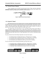
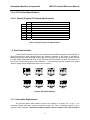
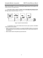
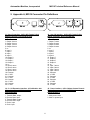
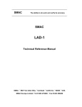
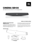
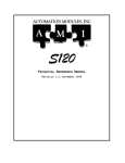
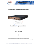
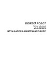
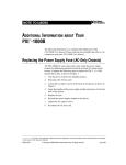
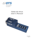
MIO16
TECHNICAL REFERENCE MANUAL
Revision 1.0, April 1998
AUTOMATION MODULES, INC.
FOX ISLAND, WA 98333
PHONE: 1-253-549-4868 / FAX: 1-253-549-4866
FOR TECHNICAL ASSISTANCE CALL:
© COPYRIGHT 1998, AUTOMATION MODULES, INC.
Automation Modules, Incorporated
MIO16 Technical Reference Manual
Table of Contents
1. INTRODUCTION....................................................................................................................................... 7
1.1 SPECIFICATIONS ........................................................................................................................................ 7
1.2 DIGITAL I/O INTERFACE ............................................................................................................................. 7
1.2.1 General Purpose Inputs ................................................................................................................... 7
1.2.2 General Purpose Outputs................................................................................................................. 8
1.2.3 Digital I/O "States" ............................................................................................................................ 8
1.2.4 I/O Technical Specifications ............................................................................................................. 9
1.3 SERIAL DATA INTERFACE ........................................................................................................................... 9
1.3.1 Connection Requirements................................................................................................................ 9
2. APPENDIX A, MIO16 CONNECTOR PIN DEFINITIONS...................................................................... 11
3. INDEX ..................................................................................................................................................... 12
5
Automation Modules, Incorporated
MIO16 Technical Reference Manual
6
Automation Modules, Incorporated
MIO16 Technical Reference Manual
1. Introduction
The MIO16 is an input / output (I/O) expansion module for use with the S100, S120, S200, S400
and SB100 family of servo controllers. It has 8 channels each of undedicated optoisolated input and
output. With a power supply input range of 11-50 VDC, the MIO16 can gets its power from the same
source as the servo controller it is used with. Communication with the host servo controller is achieved
with a proprietary synchronous serial interface using 6-pin modular connectors. A DIP switch is provided
for addressing purposes in telling the MIO16 which group of 8 I/O channels it should occupy. Lastly, a
dual LED display indicates the presence of power supply and when the MIO16 is communicating with the
host controller.
1.1 Specifications
Description
General Purpose Digital I/O
Communication Interface
Supply Voltage
Dimensions
Weight
I/O Expansion Module
8 Optoisolated Inputs, 8 Optoisolated Outputs
Proprietary Synchronous Serial Channel
+11 To +50 VDC
Approximately 4.0” Long by 3.3” Wide by 1.1” Thick
Approximately 1 Lb.
Table 1. Specifications.
1.2 Digital I/O Interface
The MIO16 includes 8 channels of general purpose digital input and 8 channels of general
purpose digital output. All of these I/O are protected through the use of optoisolators.
1.2.1 General Purpose Inputs
Figure 1 illustrates one of the MIO16’s general purpose inputs. These inputs are galvanically
isolated from the MIO16. Current of the proper polarity must be supplied to the circuit to activate the
input.
Figure 1. MIO16 General Purpose Inputs.
7
Automation Modules, Incorporated
MIO16 Technical Reference Manual
1.2.2 General Purpose Outputs
Figure 2 illustrates one of the MIO16’s general purpose outputs. These outputs are galvanically
isolated from the MIO16. When an output is activated, positive current will flow from the collector of the
optocoupler transistor (the output pin) to its emitter (the output return pin).
Figure 2. MIO16 General Purpose Output.
1.2.3 Digital I/O "States"
With regard to the host servo controllers, there are several commands that deal with controlling
the digital I/O. All of these commands operate based on the following philosophy: With regard to an input,
"active" means there is sufficient current flowing through that input and "inactive" means there is lack of
sufficient current through that input. With regard to outputs, "active" means the ability for an output to
pass current and "inactive" means the inability for an output to pass current.
The Channel High (CH) and Channel Low (CL) commands provide the user with the ability to
determine whether a channel is active in the "on" state (CH) or active in the "off" state (CL). This is
analogous to a switch and to whether it is normally open or normally closed. The Channel On (CN) and
Channel Off (CF) commands do exactly as they imply in that they will turn a given output either on or off,
which will make that output either active or inactive depending on the CH and CL commands as stated
previously.
The (CH) command causes the following interpretation of the inputs and outputs:
•
•
•
•
An "activated" output is considered to be ON (e.g., Channel On “CN” command).
An "inactivated" output is considered to be OFF (e.g., Channel Off “CF” command).
An "activated" input is considered to be ON (e.g., Do If On “DN” command).
An "inactivated" input is considered to be OFF (e.g., Do If Off “DF” command).
The (CL) command causes the following interpretation of the inputs and outputs:
•
•
•
•
An "activated" output is considered to be OFF (e.g., Channel Off “CF” command).
An "inactivated" output is considered to be ON (e.g., Channel On “CN” command).
An "activated" input is considered to be OFF (e.g., Do If Off “DF” command).
An "inactivated" input is considered to be ON (e.g., Do If On “DN” command).
Input Current
Flowing
No Flow
“CH”
On
Off
“CL”
Off
On
Output Current
Flowing
No Flow
Table 2. I/O States.
8
“CH”
CN
CF
“CL”
CF
CN
Automation Modules, Incorporated
MIO16 Technical Reference Manual
1.2.4 I/O Technical Specifications
1.2.4.1 General Purpose I/O Nominal Specifications
5
0.83
24
4.87
1.1
6
40
100
Unit
V
mA
V
mA
V
V
V
mA
Specification
Minimum voltage to activate input.
Input current at minimum activation voltage.
Maximum input voltage.
Input current at maximum voltage.
Maximum voltage to deactivate input.
Absolute maximum reverse input voltage.
Maximum voltage output can sustain.
Maximum current output can sustain.
Table 3. General Purpose I/O Specifications.
1.3 Serial Data Interface
Communication between the host servo controller and the MIO16 modules is achieved with an
RS-422 synchronous serial interface using 6-pin modular connectors. A DIP switch is provided for
addressing purposes in telling the MIO16 which group of 8 I/O channels it should occupy. Figure 3 shows
the valid module addresses and what I/O channels that particular address occupies. This allows for a
total of up to 64 I/O points. In most cases, channels 0 - 7 are reserved for the host controller so a module
using the setting with all DIP switches down would not function.
Figure 3. DIP Switch Settings.
1.3.1 Connection Requirements
The communications cable needed to connect the modules is a simple “pin 1 to pin 1”, six
conductor modular cable with modular connectors at each end. This is sometimes referred to as a
“reversed” cable assembly. The distance between modules and the length of the cable should be
9
Automation Modules, Incorporated
MIO16 Technical Reference Manual
kept as short as possible. The same type of cable assembly can be used to connect the host to the first
module as well as for daisy chaining from the first module to additional modules. The connection to the
modules need not be in any particular order.
Each MIO16 module is capable of operating from the same DC power supply as its host
controller. This can be convenient, but it is important to note that each MIO16 module should have a
direct ground path to the host controller. See Figure 4.
Figure 4. Typical Connection Scheme.
It is important to note a couple of items that will ensure proper operation of the MIO16
modules with their host controller:
•
While it is okay for the host controller to be powered while MIO16 modules are not powered,
when MIO16 modules are powered-up, the host should not try to communicate with them (i.e.
I/O commands).
•
MIO16 modules should all be powered-up at the same time.
10
Automation Modules, Incorporated
MIO16 Technical Reference Manual
2. Appendix A, MIO16 Connector Pin Definitions
J1- User I/O Interface : 26-Pin H/D Female D-Sub
Mating Connector: NorComp# HDT26P
Digi-Key# T826M
J4 - User I/O Interface : 26-Pin H/D Female D-Sub
Mating Connector: NorComp# HDT26P
Digi-Key# T826M
1. Output 3 return
2. Output 2 return
3. Output 1 return
4. Output 0 return
5. nc
6. Input 3
7. Input 2
8. Input 1
9. Input 0
10. Output 3
11. Output 2
12. Output 1
13. Output 0
14. nc
15. Input 3 return
16. Input 2 return
17. Input 1 return
18. Input 0 return
19. Common
20. +5 VDC
21. Common
22. +5 VDC
23. Common
24. +5 VDC
25. Common
26. +5 VDC
1. Output 7 return
2. Output 6 return
3. Output 5 return
4. Output 4 return
5. nc
6. Input 7
7. Input 6
8. Input 5
9. Input 4
10. Output 7
11. Output 6
12. Output 5
13. Output 4
14. nc
15. Input 7 return
16. Input 6 return
17. Input 5 return
18. Input 4 return
19. Common
20. +5 VDC
21. Common
22. +5 VDC
23. Common
24. +5 VDC
25. Common
26. +5 VDC
J2, J3 - I/O Expansion Interface : 6-Pin Modular Jack
Mating Connector: AMP# 5-641337-3
Digi-Key# A9093
J5 - Power Interface : 4-Pin 5.08mm Centers Phoenix
Mating Connector: OnShore# EDZ95002
Digi-Key# ED1717
1. Transmit Data- output
2. Receive Data- input
3. Transmit Data+ output
4. Receive Data+ input
5. Clock+ input
6. Clock- input
1. Main power return
2. Main V+ power input
11
Automation Modules, Incorporated
MIO16 Technical Reference Manual
3. Index
A
Appendix A
Connector Pin Definitions • 11
C
Connection requirements • 9
D
Digital I/O "states" • 8
Digital I/O interface • 7
G
General purpose inputs • 7
General purpose outputs • 8
I
I/O technical specifications • 9
Introduction • 7
S
Serial data interface • 9
Specifications • 7
T
Table of Contents • 5
12