1
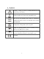
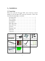
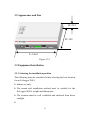
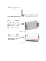
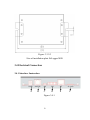
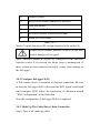
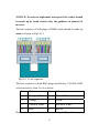
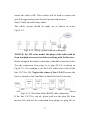
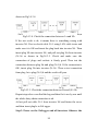
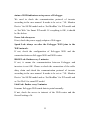
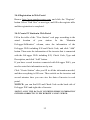
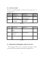
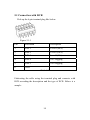
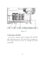
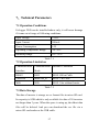
User Manual EzLogger WiFi Ver 02 Table of Contents 1、Symbols . . . . . . . . . . . . . . . . . . . . . . . . . . . . . . . . . . . . . 01 2、Safety . . . . . . . . . . . . . . . . . . . . . . . . . . . . . . . . . . . . . . 02 3、Installation . . . . . . . . . . . . . . . . . . . . . . . . . . . . . . . . . . . 03 3.1 Unpacking . . . .. . . . . . . . . . . . . . . . . . . . . . . . . . . . . 03 3.2 Appearance and Size. . . . . . . . . . . . . . . . . . . . . . . . . . 04 3.3 Equipment Installation . . . . . . . . . . . . . . . . . . . . . . . 04 3.4 Electrical Connection . . . . . . . . . . . . . . . . . . . . . . . . 06 4、Indicator Lights . . . . . . . . . . . . . . . . . . . . . . . . . . . . . . . 13 5、Operation with Ripple Control Receiver (RCR). . . . . . . 13 5.1 Connection with RCR . . . . . .. . . . . . . . . . . . . . . . . . . 14 5.2 Operation with RCR .. . . . . . .. . . . . . . . . . . . . . . . . . . 14 6、Reset and Reload .. . . . . . . . . . . . . . . . . . . . . . . . . . . . . . 16 7、Technical Parameters . . . . . . . . . . . . . . . . . . . . . . . . . . 17 7.1 Operation Conditions . . . . . . . . . . . . . . . . . . . . . . . . . 17 7.2 Operation Limitation . . .. . . . . . . . . . . . . . . . . . . . . . . 17 7.3 Data Storage . . . . . . . . .. . . . . . . . . . . . . . . . . . . . . . . 17 8、Certificates .. . . . . . . . . . . . . . . . . . . . . . . . . . . . . . . . . . 18 1、Symbols Caution! - Failure to observe a warning indicated in this manual may result injury. Product should not be disposed as household waste. This side up; the package must always be transported, handled and stored in such a way that the arrows always point upwards. Components of the product can be recycled. Fragile; the package/product should be handled carefully and never be tipped over or slung. Keep dry; the package/product must be protected from excessive humidity and must be stored under cover. CE Mark 1 2、Safety The EzLogger WiFi strictly conforms to related safety rules in design and test. Safety regulations relevant to the location shall be followed during installation, commissioning, operation and maintenance. Improper operation may cause serious injury, electric shock and/or damage to the equipment and property. Ensure children are kept away from EzLogger WiFi. Do not open the front cover of the EzLogger WiFi. Apart from performing work at the wiring terminal (as instructed in this manual), touching or changing components without authorization may cause injury to people, damage to EzLogger WiFi and annulment of the warranty. Static electricity may damage electronic components. Appropriate methods must be adopted to prevent such damage to the EzLogger WiFi; otherwise the EzLogger WiFi may be damaged and the warranty annulled. 2 3、Installation 3.1 Unpacking When you receive the EzLogger WiFi, please check for external damage to the EzLogger WiFi and any accessories. Please also check that the following are included: EzLogger WiFi. . . . . . . . . . . . . . . . . . . . . . . . . . . . . . . . 1 Power Adapter . . . . . . . . . . . . . . . . . . . . . . . . . . . . . . . . 1 Fixing Bracket . . . . . . . . . . . . . . . . . . . . . . . . . . . . . . . . 2 Screw M3*8 . . . . . . . . . . . . . . . . . . . . . . . . . . . . . . . . . 4 Mini USB Cable. . . . . . . . . . . . . . . . . . . . . . . . . . . . . . . 1 Micro SD Card . . . . . . . . . . . . . . . . . . . . . . . . . . . . . . . 1 Antennae. . . . . . . . . . . . . . . . . . . . . . . . . . . . . . . . . . . . 1 Warranty Card . . . . . . . . . . . . . . . . . . . . . . . . . . . . . . . 1 Flash Disk . . . . . . . . . . . . . . . . . . . . . . . . . . . . . . . . . . . 1 Connector.. . . . . . . . . . . . . . . . . . . . . . . . . . . . . . . . . . . 1 EzLogger Wifi Mini USB Cable Flash Disk Power Adapter Micro SD Card Connector 3 Fixing Bracket Screw M3*8 Antennae Warranty Card 3.2 Appearance and Size H=31.2 W=103 L=146.0 Figure 3.2.1 3.3 Equipment Installation 3.3.1 Selecting the installation position The following must be considered when selecting the best location for an EzLogger WiFi: Indoor use only. The mount and installation method must be suitable for the EzLogger WiFi's weight and dimensions. The location must be well ventilated and sheltered from direct sunlight. 4 3.3.2 Mounting Procedure Screw on the antennae at first: Step 1 : Assemble EzLogger and Fixing Bracket as shown in the Graph 3.3.2-1, and tighten them by Screws M3*8 in the accessory bag. Figure 3.3.2-1 Step 2 : Tighten EzLogger by Screws φ4*12. Installation dimensions are shown in the Graph 3.3.2-2. Figure 3.3.2-2 5 Figure 3.3.2-3 Size of installation plate EzLogger WiFi 3.4 Electrical Connection 3.4.1 Interface Instruction A A B C D Figure 3.4.1 6 E F A Adapter Socket B RS485 RJ45 Socket (connects to inverter) C USB port Socket D 6pin Terminal Socket E LAN RJ45 Socket, Reserved for future F Micro SD Card Socket Table 3.4.1 Notice: Unpack the micro SD card and insert it to the socket (F) Please do not confuse interface B and E as this will lead to damage to EzLogger! Note: Interface socket B should be connected to the inverter. Interface socket E is reserved for future, keep it unconnected. If these sockets are not connected correctly, it may cause damage to the EzLogger. 3.4.2 Configure EzLogger WiFi A WiFi router device is essential for internet connection. Be sure to keep the EzLogger WiFi in the area that WiFi signal could reach. And configure WiFi follow the instruction of document named “WiFi Configuration” in the flash disk. Here the configuration of EzLogger WiFi is completed. 3.4.3 Make Up The Cable Daisy Chain Connection Step1: First of all, make up cables 7 NOTICE: In order to implement waterproof, the cables should be made up by hand strictly obey the guidance in manual of inverter. The line sequence of both plugs of RS485 cable should be made up same as shown in Fig3.4.3.1. Fig3.4.3.1 Line sequence The line sequence in both RJ45 plugs should obey TIA/EIA-568B criterion strictly, from 1 to 8 as below: Line Color Line Color 1 Orange & White 5 Blue & White 2 Orange 6 Green 3 Green & White 7 Brown & White 4 Blue 8 Brown Besides that, each cable should be tested by LAN cable tester to 8 ensure the cable is OK. These cables will be used to connect not only EzLogger and inverter but also inverter and inverter. Step2: Check the cable daisy chain The whole system should be made up as shown in below Fig3.4.3.2. Fig3.4.2.2. Whole system connection diagram NOTICE: For DT series model, the plugs of the cable shall be from standard accessory box delivered along with the Inverter. Before complete the whole connection, it should be tested as below: Test the connection from plug 1a to plug (N+1)b as shown in Fig3.4.3.3. If everything is ok, the LAN cable tester will tell the line 3/6/7/8 is OK. Neglect the status of line 1/2/4/5 because the line1 is shorted to line2 and line4 is shorted to line5 in inverter. Fig3.4.3.3. Check the whole RS485 cable connection If the line 3/6/7/8 is not ok, please pull out the plug Nb from inverter N#, and test the connection from plug1a to plug Nb, as 9 shown in Fig3.4.3.4. Fig3.4.3.4. Check the connection between 1a and Nb If the test result is ok, it means there is something wrong with inverter N#. First re-check cable N+1 using LAN cable tester and make sure it is OK and insert the plug back into inverter N#. Then insert plug Nb into inverter N#, and pull out plug Na from inverter (N-1)# as shown in Fig3.4.3.5. Check and make sure the connection of plugs and sockets is firmly good. Then test the connection between plug Na and plug (N+1)b. If the connection is OK, insert plug Na into inverter (N-1)#. Then re-test connection from plug 1a to plug (N+1)b and the result will pass. Fig3.4.3.5. Check the connection between Na and (N+1)b Repeat steps above can find the bug and then fix it one by one until the whole daisy chain connection is ok. At last pull out cable N+1 from inverter N# and fasten the cover and then insert plug1a to EzLogger. Step3: Power on the EzLogger and all inverters. Observe the 10 status of LED indicators on top cover of EzLogger. We need to check the communication protocol of inverter according to the user manual. It needs to be set as ‘.VS. Monitor Device’ for SS/DS model and as ‘Set ModBus’ for DT model and as ‘Set Web’ for Smart DT model. If everything is OK, it should be like below: Power led: always on If not, check the power supply adaptor of EzLogger. Speed Led: always on after the EzLogger WiFi joins to the WiFi network. If not, check the configuration of EzLogger WiFi and the connection between EzLogger WiFi and WiFi router. RS485 Led: flashes every 3 minutes. If not, it means the communication between EzLogger and inverters is not OK. Please re-check the connection of the cable daisy chain and check the communication protocol of inverter according to the user manual. It needs to be set as ‘.VS. Monitor Device’ for SS/DS model and as ‘Set ModBus’ for DT model and as ‘Set Web’ for smart DT model. Link Led: flashes every 9 minutes It means EzLogger WiFi sends data to portal normally. If not, check the access to internet of the WiFi router and the firewall setting of it. 11 3.4.4 Registration in Web Portal Browse http://www.goodwe-power.com, and click the “Register” button. Select “End User” as user type, and fill in the register table and the registration is completed. 3.4.5 Create PV Station in Web Portal Fill in the table of the “New Station” web page according to the actual location of your station. In the “Maintain EzLogger/EzMonitor” column, enter the information of the EzLogger WiFi including S/N and Check Code, and click “Add” button. Then enter the information of the inverter that is connected with the EzLogger WiFi including S/N, Check Code, Type and Description, and click “Add” button. If you have several inverters connected with EzLogger WiFi, you need to enter their information one by one. Click “Create Station” after you fill in all the information needed, and then everything is OK now. Then switch on the inverters and several minutes later you can view the data of inverter in web portal. NOTICE: you can find S/N and Check Code on the back side of EzLogger WiFi and right side of inverter. NOTICE: ONLY THE DATA OF INVERTER WHOSE INFORMATION ENTERED CORRECTLY IN THE WEBSITE CAN BE VIEWED. 12 4、Indicator Lights There are 6 indicator lights on left side of the front cover of EzLogger WiFi. Label POWER SPEED Light On Powered on Joined to Light Off Powered off Disconnected from Colour Green Yellow RCR WiFi network Received command WiFi network No command Yellow from RCR from RCR Table 4-1 Label Flickering Light Off Colour LINK Communicates with Data Interval Yellow Data Interval Yellow No File Transmission Yellow Portal RS485 Communicates with Inverter USB File Transmission to PC Table 4-2 5、Operation with ripple control receiver The EzLogger WiFi can be connected with ripple control receiver (RCR for short) and executes the command from it. 13 5.1 Connection with RCR Pick up the 6-pin terminal plug like below: Figure 5.1-1 Pin Allocation Description 1 D.IN.1 Level 1(60%) 2 D.IN.2 Level 2(30%) 3 D.IN.3 Level 3(0%) 4 D.IN.4 0.95 Lagging 5 D.IN.5 0.90 Lagging 6 GND Table 5.1 Fabricating the cable using the terminal plug and connects with RCR according the description and the type of RCR. Below is a sample: 14 Figure 5.1-2 5.2 Operation with RCR Just keep the connection between EzLogger WiFi and RCR stable, and both powered on. Then you need not do anything else. The EzLogger WiFi will execute the command from RCR automatically. 15 6、Reset and Reload EzLogger WiFi Figure 6 There are two buttons in the right side of EzLogger. One is the Reset button, press this button to restart the EzLogger . The reload button is used to reload the default configuration of network parameter of EzLogger. Press this button longer than 3 seconds to the change the EzLogger to default configuration. Notice: All configurations have to be set once again after using reload function. 16 7、Technical Parameters 7.1 Operation Conditions EzLogger WiFi can be installed indoor only; it will cause damage if it runs out of range of following conditions: Input Voltage 9 VDC Input Current 500m A Power Consumption 4W Operating Temperature Range -20~60°C Humidity Range 0% - 95% Table 7.1 7.2 Operation Limitation Communication Communication Distance Limitation Interface Mode RS485 RJ45 MAX. 800 m Cable USB Port MiniUSB_B MAX. 2 m Cable WiFi WiFi MAX. 10m without barrier Table 7.2 7.3 Data Storage The data of inverter is storage as csv format files in micro SD card. Its capacity is 8GB which is only available for data of 20 inverters not longer than 3 years. When the space is using up, the oldest data files will be deleted. And you can download the csv file via a micro SD card reader or the USB cable. 17 8、Certificates Figure 8 18