1
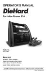
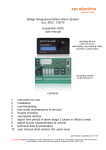
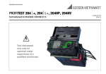
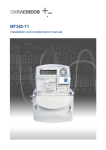
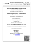
Bridge Navigational Watch Alarm System
acc. MSC .128/75
U-WAS 2000
user manual
operating device
LOD 210.24.0.0
with display, key switch & rotary
encoder w. push button
connecting module
LCM 210.24.0.0
contents
1
2
3
4
5
6
7
8
9
10
instruction for use
installation
commissioning
test mode (maintenance & service)
trouble shooting
centralized dimmer
adjust time period of alarm stage 2 (alarm in officer’s area)
adjust buzzer characteristics & volume
technical data & schematics
user manual short version (for users only)
U-WAS 2000 User Manual R01.06
1/39
Martechnic Ltd. +30(210)4227267
1 instruction for use
U-WAS 2000 and its extension devices (time period reset units, alarm devices)
must only be installed by trained electricians or other persons who are familiar
with installation of electric equipment.
Parts of the system can be damaged and persons put at risk if system is
connected incorrectly.
Connecting module (LCM 210.24.0.0) is designed to be installed in an enclosure
switch cabinet or control console. For service and commissioning work
connecting module should be installed in such manner, service personnel is able
to see state LEDs on module.
Operating device (LOD 210.24.0.0) is designed to be installed on control
console.
Operating device and all time period reset units have to be installed only at
locations on bridge or bridge wings where OOW has a proper look out.
Installation must conform to regulations for electromagnetic compatibility (EMC).
(see chapter technical data & schematics)
U-WAS 2000 User Manual R01.06
2/39
Martechnic Ltd. +30(210)4227267
2 installation
Connecting module (LCM 210.24.0.0) and its extension devices (time period
reset units, alarm devices) have to be connected according to corresponding
wiring diagrams.
fuse holders
-F1, -F2 (m2A)
terminals for
24VDC power supply
-Z1
15 pole connector
to operating device
connecting module
LCM 210.24.0.0
terminals for
periphery equipment
description
connecting module (LCM 210.24.0.0)
Module has been designed to click on terminal rail TS 35 inside electric cabinet
or control console. All periphery equipment (time period reset units, alarm
panels, power supply) is to be connected directly on connecting module without
any additional terminal board or distribution boxes according to wiring diagram
which is part of working drawings. Sample system wiring diagram is shown in
chapter “technical data & schematics”.
Outputs for “power on” indication and time period reset push button illumination
are short-cut protected. Maximum loads of outputs and output contacts see
chapter “technical data & schematics”.
U-WAS 2000 User Manual R01.06
3/39
Martechnic Ltd. +30(210)4227267
key switch
S1
2x16 character
illuminated display
rotary encoder incl.
push button S2
operating device
LOD 210.24.0.0
operating device (LOD 210.24.0.0)
Before mounting operating device into cut-out, plug on 15-pole system cable on device’s
rear side and tighten it properly. Use device clamps to fix device in proper manner.
Do not use longer system cable as standard length: l=3m!
Plug on 15-pole system cable on connecting module LCM 210.24.0.0 (-Z1) and
tighten it properly.
After connecting all additional equipment (time period reset units, alarm devices)
according to corresponding wiring diagram, system is ready for operating.
U-WAS 2000 User Manual R01.06
4/39
Martechnic Ltd. +30(210)4227267
3 commissioning
Before switching on 24VDC (nominal) power supply to connecting module LCM
210.24.0.0 terminal board –X1: 1,2 (+) & 3,4 (-) make sure power supply, time
period reset units and external alarm devices have been connected correctly
according to wiring diagram.
Diode on LCM 210.24.0.0 connecting module secures system against wrong
power supply polarity.
system fail relay
K1 with control LED 1
After switching on 24VDC power supply (generally from 24VDC Emergency
Distribution Board) system fail relay K1 is activated and display on operating
device LOD 210.24.0.0 shows “text 1” after a short intro procedure.
In case of system fail, relay K1 is not activated (control LED D9 is switched off).
When system is running properly, relay K1 is triggered and its potential free
contact is closed (-X1: 5, 6)
Make sure that up to now no external “power on” contact (steady contact: X1:29, 30 and pulsed contact: -X1: 26, 27 & 50, 51) is active.
display „text 1“
U-WAS 2000 User Manual R01.06
READY FOR
POWER ON / AUTO
5/39
Martechnic Ltd. +30(210)4227267
System is running now and is waiting for user’s operation on operating device
LOD 210.24.0.0 or for an external “power on” command. Display shows “text1”.
Switch on system by turning key switch S1 on operating device LOD 210.24.0.0
one time to position “ON/OFF”
After system is switched on default dormant period (3:00min) is counting down
and display shows current state of count-down (display “text 3”).
key switch
S1
2x16 character
illuminated display
rotary encoder incl.
push button S2
operating device
LOD 210.24.0.0
display „text 2“
COUNT-DOWN
*** 2:59 ***
Test of external illuminated time period reset unit:
In this “count-down mode” all illuminated time period reset units are activated.
Illumination of display and of reset units is adjustable by turning rotary encoder.
Minimum illumination is fixed.
Now push external reset units (one by one) and check 2nd line of display (current
value). Every reset should restart count-down ( 2:59).
U-WAS 2000 User Manual R01.06
6/39
Martechnic Ltd. +30(210)4227267
Test of external “power on” devices: (optional)
In case external “power on” devices are involved, activate these devices (one by
one). Make sure before, display “text 1” is shown. Only in this “auto mode” an
external “power on” is possible.
display „text 1“
READY FOR
POWER ON / AUTO
notice:
Every switching on (from operating device LOD 210.24.0.0 or from external
devices) restarts count-down!
Test of external alarm devices and links
For checking alarm devices (external buzzers on bridge or bridge wing area,
alarm panels in officer’s area, link to general alarm system, link to VDR system
and system failure contact see chapter 4 “test mode” (maintenance & service)
For finishing commissioning procedure “switch off” system by turning key switch
S1 on operating device LOD 210.24.0.0 to position “ON/OFF” for longer than 2
sec.
Display shuts down and system ignores all external inputs now.
system is
shut down
U-WAS 2000 User Manual R01.06
7/39
Martechnic Ltd. +30(210)4227267
4 test mode (maintenance & service)
U-WAS 2000 Bridge Navigational Watch Alarm System owns a test mode
procedure to check all output relevant devices (alarm panels, external buzzers,
links to alarm devices, links to VDR and system failure contact) in a very
comfortable manner.
To reach this “service mode” an authorized person has to “switch off” system by
turning key switch S1 on operating device LOD 210.24.0.0 to position “ON/OFF”
for longer than 2 sec. System shuts down. After that authorized person has to
keep pushing rotary encoder push button S2 and after a period between 2 and 3
sec he has to “switch on” system by turning key switch S1 on operating device
LOD 210.24.0.0 one time to position “ON/OFF”
key switch
S1
2x16 character
illuminated display
operating device
LOD 210.24.0.0
rotary encoder incl.
push button S2
System starts in “service mode” and display is showing “text 4”
display „text 4“
TEST MODE 1 OFF
ALARM on BRIDGE
By pushing rotary encoder’s push button S2 for one time, all internal and
external bridge area alarm devices (alarm stage 1) are activated as long as push
button S2 is pushed again. During this manual alarm activation, display is
showing “text 5”.
display „text 5“
U-WAS 2000 User Manual R01.06
TEST MODE 1 ON
ALARM on BRIDGE
8/39
Martechnic Ltd. +30(210)4227267
After a.m. test in “test mode 1” is done, user has to turn rotary encoder
clockwise to reach “test mode 2”.
display „text 6“
TEST MODE 2 OFF
OFFICERs ALARM
Display is showing “text 6” and after pushing rotary encoder’s push button S2 for
one time, all alarm devices in officer’s area (alarm stage 2) and link to VDR
system (optional) are activated as long as push button is pushed again.
During this manual alarm activation, display is showing “text 7”.
display „text 7“
TEST MODE 2 ON
OFFICERs ALARM
After a.m. test in “test mode 2” is done, user has to turn rotary encoder
clockwise to reach “test mode 3”.
display „text 8“
TEST MODE 3 OFF
ALARM STAGE 3
Display is showing “text 8” and after pushing rotary encoder’s push button S2 for
one time, system’s contact is activating very loud alarm devices in officer’s area
(alarm stage 3) and link to VDR system (optional) as long as push button is
pushed again.
During this manual alarm activation, display is showing “text 9”.
display „text 9“
U-WAS 2000 User Manual R01.06
TEST MODE 3 ON
ALARM STAGE 3
9/39
Martechnic Ltd. +30(210)4227267
After a.m. test in “test mode 3” is done, user has to turn rotary encoder
clockwise to reach “test mode 4”.
display „text 10“
TEST MODE 4 OFF
DEVICE FAILURE
Display is showing “text 10” and after pushing rotary encoder’s push button S2
for one time, device’s failure contact opens and activate linked alarm system as
long as push button S2 is pushed again.
Consider possible alarm delay period created by linked alarm system!
During this manual alarm activation, display is showing “text 11”.
display „text 11“
TEST MODE 4 ON
DEVICE FAILURE
State of all output relays is shown by corresponding control LEDs. Consider
reversed relay logic of system failure relay K1!
connecting module
LCM 210.24.0.0
alarm stage 1 relay
K2 with control LED 2
system fail relay
K1 with control LED 1
U-WAS 2000 User Manual R01.06
alarm stage 3 relay
K4 with control LED 4
alarm stage 2 relay
K3 with control LED 3
10/39
Martechnic Ltd. +30(210)4227267
For finishing “test mode” procedure “switch off” system by turning key switch S1
on operating device LOD 210.24.0.0 to position “ON/OFF”.
key switch
S1
2x16 character
illuminated display
operating device
LOD 210.24.0.0
U-WAS 2000 User Manual R01.06
11/39
rotary encoder incl.
push button S2
Martechnic Ltd. +30(210)4227267
5 trouble shooting
fuse holder
F1, F2
connecting module
LCM 210.24.0.0
system fail relay
K1 with control LED 1
system fail criteria
In following cases potential free (dry) n/o contact on connecting module LCM 210.24.0.0
–X1: 5,6 opens (system fail state):
a) power supply failed (or main power supply voltage is lower than 13,2V)
b) program cycle interrupted (risc controller has been stopped)
c) link with 15 pole system cable Z1 between operating device and connecting
module is interrupted
a) check supply voltage by comparing it with other systems fed from same distribution
source.
b) Switch off system’s power supply for minimum 10 sec by opening fuse holder F1
or F2 on connecting module LCM 210.24.0.0. After switching on power supply,
program will start automatically after 2 sec. in “normal mode”.
c) check system cable between connecting module LCM 210.24.0.0 and operating
device LOD 210.24.0.0, especially system plug on operating device’s rear side.
Cable might be damaged.
U-WAS 2000 User Manual R01.06
12/39
Martechnic Ltd. +30(210)4227267
System fail state is indicated when system fail relay K1 is not triggered (control LED
D9 is off).
Notice:
In case that during watch operations system’s power supply fails temporary (e.g.
black-out situation) watch operations restart automatically with old settings (settings
before power fail).
time period cannot reset, emergency call cannot reset
check all reset units if reset contact is closed permanently by switch’s malfunction or
accidental use.
No indication light is active (reset units & external “power on” devices)
Check if system is might be “switched off” by external system. Use key switch S1 on
operating device LOD 210.24.0.0.
Notice:
time period reset unit illumination and external “power on” indication are active only,
when count-down sequence is started.
If system works properly but without any indication, one bulb or LED in time period
reset units or external “power on” devices might be blown in that way, causing a shortcircuit. Replace damaged bulb / LED. Short-circuit does not damage system due to
short-circuit protected transistor outputs.
U-WAS 2000 User Manual R01.06
13/39
Martechnic Ltd. +30(210)4227267
6 centralized dimmer
U-WAS 2000 BNWAS is designed with a centralized dimmer function. That means all
relevant illuminated time period reset units on bridge and bridge wing area as well as blue
display on operating device LOD 210.24.0.0 are adjustable by turning rotary encoder S2
on operating device LOD 210.24.0.0. Minimum illumination is limited. Dispay’s illumination
and time period reset unit’s illumination are sychronized.
key switch
S1
2x16 character
illuminated display
operating device
LOD 210.24.0.0
rotary encoder incl.
push button S2
By turning rotary encoder S2 on operating device LOD 210.24.0.0 in counter clock wise
direction, illumination is decreasing. By turning rotary encoder S2 on operating device
LOD 210.24.0.0 in clockwise direction, illumination is increasing.
Notice:
dimmer function is suppressed during any kind of settings changing procedure by
using rotary encoder!
U-WAS 2000 User Manual R01.06
14/39
Martechnic Ltd. +30(210)4227267
7 adjust time period of alarm stage 2 (alarm in officer’s area)
(for authorized persons only)
IMO regulations allow (MSC 75/24/Add.1 ANNEX 11, 4.1.2.7) to increase standard setting
of 90 sec of alarm stage 2 (alarm in officer’s area). Compare with chapter 9 technical data
and schematics (see watch alarm time table). Adjustment could be necessary due to
large vessel. Period can be adjusted to max. 180sec (default value is 90sec), to allow
sufficient time for back-up officer and/or Master to reach bridge area before watch alarm
system is triggering alarm stage 3.
Write down decided new value here:
new time period of alarm stage 2
[90sec.... 180sec]
date & sign
To adjust a.m. time period turn key switch S1 on operating device LOD 210.24.0.0 to
position “SELECT”.
key switch
S1
2x16 character
illuminated display
rotary encoder incl.
push button S2
operating device
LOD 210.24.0.0
U-WAS 2000 User Manual R01.06
15/39
Martechnic Ltd. +30(210)4227267
After turning key switch S1 to position “SELECT” display is showing “text 3”.
display „text 3“
SET MAIN PERIOD:
3… 12min ** 3 **
Now push rotary encoder’s push button S2 on operating device LOD 210.24.0.0 so often
as display is showing “text 24”.
display „text 24“
PERIOD ADJUST
AL.STAGE 2 090s
Now turn rotary encoder in clockwise direction to increase time period value or in counterclock wise direction to decrease time period value. System allows only values between 90
and 180sec. By pushing rotary encoder’s push button S2 on operating device LOD
210.24.0.0 display is changing and system accepts adjusted value.
U-WAS 2000 User Manual R01.06
16/39
Martechnic Ltd. +30(210)4227267
8 adjust buzzer characteristics & volume
U-WAS 2000 system is designed with adjust mode to be able to change steady internal
and external alert tone into 7 additional individual buzzer characteristics in case other
systems on bridge area are generating a similar alert tone.
Adjust buzzer’s characteristic
To adjust buzzer’s characteristic turn key switch S1 on operating device LOD 210.24.0.0
to position “SELECT”.
key switch
S1
2x16 character
illuminated display
operating device
LOD 210.24.0.0
rotary encoder incl.
push button S2
After turning key switch S1 to position “SELECT” display is showing “text 3”.
display „text 3“
SET MAIN PERIOD:
3… 12min ** 3 **
Now push rotary encoder’s push button S2 on operating device LOD 210.24.0.0 so often
as display is showing “text 22”.
display „text 22“
BUZZERs
PROPERTIES 1
Now turn rotary encoder to choose an adequate buzzer characteristic. By pushing rotary
encoder’s push button S2 display is changing and system accepts adjusted value.
Do not accept offered buzzer characteristics during buzzer is activated
(Wait for the brake!)
U-WAS 2000 User Manual R01.06
17/39
Martechnic Ltd. +30(210)4227267
Adjust internal buzzer’s volume
To adjust internal buzzer’s volume turn key switch S1 on operating device LOD
210.24.0.0 to position “SELECT”. Minimum sound volume is limted to 65dB(A)
key switch
S1
2x16 character
illuminated display
operating device
LOD 210.24.0.0
rotary encoder incl.
push button S2
After turning key switch S1 to position “SELECT” display is showing “text 3”.
display „text 3“
SET MAIN PERIOD:
3… 12min ** 3 **
Now push rotary encoder’s push button S2 on operating device LOD 210.24.0.0 so often
as display is showing “text 23”.
display „text 23“
BUZZERs
SOUND VOLUME 15
Now turn rotary encoder in counter clock wise direction to decrease buzzer’s sound
volume or in clock wise direction to increase sound volume. By pushing rotary encoder’s
push button S2 display is changing and system accepts adjusted value.
Notice:
During alarm stage 1 (alarm on bridge & bridge wing area) internal buzzer’s sound
volume can be adjusted by turning rotary encoder on operating device!
U-WAS 2000 User Manual R01.06
18/39
Martechnic Ltd. +30(210)4227267
9 technical data and schematics
General
description:
power supply:
power consumption:
internal fuses:
degree of enclosure:
weight:
approbation:
transistor outputs:
max. load of relay contacts:
sound pressure level:
no.:
type:
operating device
1
LOD 210.24.0.0
2
U-WAS 2000 BNWAS
24VDC (nominal), 18,0… 31,2VDC, nominal feeding value: B4A
min. 60mA, max. 400mA, nominal value: 120mA
2x m2,0A, 5x20mm
acc. EN 60529 see table
connecting module: 330g, operating device: 200g
design & manufacturing acc. IEC 60945, type approvals: GL,
“power on” indication: max. 400mA, reset pb illumination: 2x 180mA
30VDC, 2A
internal buzzer 65…80dB(A) adjustable
connecting module
LCM 210.24.0.0
3 WAP 220.2.0.0
4 WAP 220.4.0.0
5 WAR 220.1.0.0
6 WAR 220.1.0.1
7 WAB 220.1.0.0
8 WAB 220.2.0.0
description:
console mounted operating device with blue illuminated display,
key switch and rotary encoder with integrated push button,
w 144 x h 72 x d 75mm
terminal board module, to be mounted on terminal rail TS35,
w 162 x h 127 x d 68mm
watch alarm panel for officer's cabin, 80 dB(A)
flush mounting
watch alarm panel for officer's area (corridor), 64-111dB(A)
bulkhead or flush mounting
watch alarm reset push button, illuminated,
connecting type: welding
watch alarm reset push button, illuminated,
connecting type: screws
watch alarm wall box with buzzer, 85 dB(A)
external watch alarm buzzer, 85 dB(A)
one whole installation, 22,5mm
safety distance
cable
to magnetic
cross-sections:
compass [m]:
weight: [kg]
degree of
enclosure
device:
0,200
cable:
0,300
front:
IP22
back:
IP00
0,5
/
0,330
IP20
0,5
0,2....1,5mm²
2x micro fuse, m2,0A, 5x20mm
part no.: 097109
0,150
front:
IP23
back:
IP00
/
0,2... 2,5mm²
1x bulb, mg28V, 40mA
part no.: 099081
0,870
IP65
/
0,2... 2,5mm²
0,045
IP67
/
0,080
IP65
/
0,750
IP65
/
1x bulb, E14, 24V, 4W
part no.: 099141
0,2...
1x bulb, T5,5, 28V, 40mA
0,75mm² part no.: 099076
1x bulb, Ba9s, 28V, 45mA
0,2... 2,5mm²
part no.: 099083
0,2... 2,5mm²
/
0,030
IP65
/
0,2... 2,5mm²
0,2... 2,5mm²
9 WAR 220.2.0.0
watch alarm wall box for reset, illuminated
0,750
IP65
/
10 WAR 220.2.1.0
watch alarm wall box for reset, illuminated with buzzer, 85 dB(A)
0,850
IP65
/
U-WAS 2000 User Manual R01.06
19/39
spare parts:
-
/
1x bulb, T5,5, 28V, 40mA
part no.: 099076
1x bulb, T5,5, 28V, 40mA
0,2... 2,5mm²
part no.: 099076
Martechnic Ltd. +30(210)4227267
sample system connecting diagrame.
3
4
5
6
7
8
k4
k4
max. load: 160mA
k3
max. load: 160mA
k3
2x0,75
max. load: 160mA
2x0,75
2x0,75
k2
2x0,75
D1
F1
F2
2
k4
2x1,5
2x m1,25A
1
1
+
2
-
5
6
1
1
2
2
5
5
6
6
ALA RM D EV IC ES
O FFIC ER 'S A RE A
S TA G E 2 ALAR M
75 - 85dB (A ), 1m
C
B
A term inal no. changed (-X 1)
m odification
U-WAS 2000 User Manual R01.06
31.8.09 T. S treit
30.5.09 T. S treit
11.2.09 T. S treit
nam e
(by using m ore than 10 indications, use LED s)
A LA RM DE VICES
O FFICE R'S A REA
S TAG E 3 ALARM
85 - 112dB (A), 1m
S hipyard
T. S treit
spare of:
A4
departm ent:
sm e
20/39
B R ID G E N A VIG A TIO N AL
W A TC H A LAR M SYS TEM
H ULL
class
GL
= + -
1
D raw ing No.
LC M 210.24.0.0AS R EVB
1
Martechnic Ltd. +30(210)4227267
CUT OUT
le guardian
75
(2.952)
8,5
(0.335)
139±0,2
(5.472)
68±0,2
(2.677)
72
(2.835)
61,61
(2.425)
2025
sm electrics
144
(5.669)
15
(0.591)
121,5
(4.783)
CONSOLE MATERIAL: max. t=8,0mm (0.315)
136
(5.354)
panel surface: black polycarbonat
print: RAL 9010
degree of enclosure, EN 60529: IP22 front sided
evenness of mounting surface < 0,1mm (to keep degree of enclosure)
weight: 0,200kg
power supply: 18,0... 31,2V
power consumption: max. 8,2W, nominal 4,0W
mm
(INCH)
U-WAS 2000 User Manual R01.06
21/39
Martechnic Ltd. +30(210)4227267
to be m ounted on term inal rail TS 35
system voltage: 18,0...31,2VD C , pow er consum ption: 20W
core size: m ax 0,2.... 1,5m m , pow er supply: 0,2.....2,5m m
degree of enclosure: IP 20
m ax. depth: 70m m
w eight: 0,35kg
safety distance to m agnetic com pass: 0.5m
Page 22 of 39
U-WAS 2000 User Manual R01.06
2008
28.9.
S treit
user manual, U-WAS 2000 vers 1.06
22/39
le guardian 2025 connecting m odule
-
BLATT: 2
V O N: 2
Martechnic Ltd. +30(210)4227267
emarks:
wall cut-out: d=68mm
for flush m ounting only!
-H1
background: white
sym bol: black
wallbox surface: RAL 7035
nom inal values: 24VDC, 350mA
sound pressure level: 64 - 111 db(A) (adjustable)
sound characteristic: 2850 Hz continuous
cable diam eter: 8,0 -16,0mm
core size: max 2,5mm
degree of enclosure: IP 65
depth without lower wall box part: 30mm
bulbs: m ax. 2x5W
weight: 0,870kg
Page 23 of 39
U-WAS 2000 User Manual R01.06
M25x1,5
FIXING HOLES
4X 6,3
M25x1,5
-H2
upper wallbox part
sound code: 11100
2005 DATUM
BEARB. 31.1.
GEZ.
-H1
-H2
+
1
+
2
3
NAME
Streit
SIGNAL DEVICE W ITH SOUNDER &
TRIANGLE LIGHT FOR W ATCH ALARM
0V
4
5
6
user manual, U-WAS 2000 vers 1.06
23/39
BLATT:
VON:
Martechnic Ltd. +30(210)4227267
remarks:
WATCH ALARM
sm electrics
surface: black anodized
print: white RAL 9010
nominal values: 24VDC, 50mA
degree of enclosure: IP 23
core size: max. 2,5mm
sounder: 80 dB(A)
depth: 45mm
weight: 0,150kg
2
2004
10.12.
Streit
WATCH ALARM PANEL WAP 220.2.0.0
for Officer's cabin
standard
U-WAS 2000 User Manual R01.06
24/39
BLATT: 1
VON: 1
Martechnic Ltd. +30(210)4227267
1
40.0
max.5.0
19.0
U-WAS 2000 User Manual R01.06
37,5
25/39
Martechnic Ltd. +30(210)4227267
1
40.0
max.8.0mm
19.0
U-WAS 2000 User Manual R01.06
66.5
26/39
Martechnic Ltd. +30(210)4227267
M32x1,5
WATCH ALARM
YE/ge
X2
X1
ge
wallbox surface: RAL 7001, depht: 90mm
nominal values: 24VDC, 50mA
cable diameter: 9,5 -20,0mm
core size: max 2,5mm
degree of enclosure: IP 65
weight: 0.850kg
2003 DATUM
BEARB. 7.12.
GEZ.
NAME
Streit
3
gr
ws
X1
ws
sw
-
bl
*
1 2 3 4 5 6
triple link in use by common 0V
WALL BOX FOR RESET
WATCH ALARM
BLATT:
U-WAS 2000 User Manual R01.06
+
X2
4
27/39
VON:
Martechnic Ltd. +30(210)4227267
M32x1,5
82.0
120.0
50.0
106.0
122.0
24VDC
YE/ge
*
* link in use by common 0V
2003 DATUM
BEARB. 7.12.
GEZ.
NAME
Streit
PART No.: 770041
BLATT:
U-WAS 2000 User Manual R01.06
28/39
VON:
Martechnic Ltd. +30(210)4227267
1
30.0
max.12.0mm
11.0
U-WAS 2000 User Manual R01.06
60.0
29/39
Martechnic Ltd. +30(210)4227267
50.0
M32x1,5
82.0
120.0
WATCH ALARM
106.0
122.0
2004 DATUM
1.3.
BEARB.
GEZ.
NAME
Streit
WALL BOX WITH BUZZER
FOR WATCH ALARM
BLATT:
U-WAS 2000 User Manual R01.06
30/39
VON:
Martechnic Ltd. +30(210)4227267
PERSONNEL ALARM
ON / OFF
GN/gn
M32x1,5
SYSTEM
ON
on / off
2005 DATUM
BEARB. 22.11.
GEZ.
NAME
Streit
gn
PART No.: 770043
BLATT:
U-WAS 2000 User Manual R01.06
31/39
VON:
Martechnic Ltd. +30(210)4227267
10 user manual short version (for users only)
U-WAS 2000 Watch Alarm System acc. MSC .128/75
(Bridge Navigational Watch Alarm System, BNWAS)
x
x
x
x
x
x
x
x
x
x
x
x
x
1.0
1.1
2.1
2.2
3.0
3.1
3.2
3.2.1
3.2.2
3.2.3
3.2.4
4.1
5.1
Generals
Installation
Manual Switch On
Automatic Switch On
Select dormant (main) period
Reset of dormant (main) period
Alert sequences start automatically
Visual indications
Alarm stage 1
Alarm stage 2
Alarm Stage 3
Emergency Call
System shut-down
1.0 Generals
The purpose of a bridge navigational watch alarm system is to monitor bridge activity and
detect operator disability which could lead to marine accidents. The system monitors
awareness of the Officer of the Watch (OOW) and automatically alerts the Master or another
qualified person if for any reason OOW becomes incapable of performing OOW’s duties.
This purpose is achieved by series of indications and alarm to alert first the OOW and, if he
is not responding, then to alert Master or another qualified person. Additionally, the BNWAS
provide the OOW with means of calling for immediate assistance if required.
This user manual (short version) is made for persons who know basic standards of watch
alarm system. All time period reset inputs are protected against permanent reset.
U-WAS 2000 User Manual R01.06
32/39
Martechnic Ltd. +30(210)4227267
1.1 Installation
After operating device LOD 210.24.0.0 and connecting module LCM 210.24.0.0 are installed
according to technical documentation by authorized personnel, system has to be supplied by
24VDC battery power supply (terminal board -X1: 1, 3). Potential free n/o failure contact
(connecting module –X1: 5, 6) closes and system is ready for switch on. After a short display
intro display on operating device is showing “text 1”.
display „text 1“
READY FOR
POWER ON / AUTO
2.1 Manual switch on
Authorized person (Master) switches on system by single turning key switch –S1 on
operating device to position “ON/OFF”. System’s running is indicated by activating last
chosen dormant (main) period and count-down is active as shown on display “text 2”.
display „text 2“
COUNT-DOWN
*** 2:59 ***
key switch
S1
2x16 character
illuminated display
operating device
LOD 210.24.0.0
rotary encoder incl.
push button S2
If dormant (main) period (3... 12 min) shall not be changed, authorized person (Master) pull
off the key. Dormant period is counting down from the moment that system has been
switched on.
Dormant period is period within OOW is monitored but no further alert is triggered.
U-WAS 2000 User Manual R01.06
33/39
Martechnic Ltd. +30(210)4227267
2.2 Automatically switch on
System can be switched on by external systems via potential free steady n/o contact which
has to be connected on connecting module LCM 210.24.0.0 –X1: 29 & 30.
Automatic switch on is possible only in automatic mode - when display is showing “text 1”.
READY FOR
POWER ON / AUTO
display „text 1“
In case automatic switch on shall not be possible, master has to shut-down system (see
chapter 5.1 System shut-down)
3.0 Select dormant (main) period
In case that authorized person (Master) demands to select other dormant period, person has
to turn key switch S1 on operating device to position “SELECT”. In this position only dormant
period can be chosen by using rotary encoder S2 on operating device. Display is showing
“text 3”.
display „text 3“
SET MAIN PERIOD:
3… 12min ** 3 **
By turning rotary encoder S2 in clock wise direction, value is increasing. By tuning rotary
encoder S2 in counter clock wise direction, value is decreasing. Possible main period value
is limited between 3 and 12 min. Step width is 1 min. By turning key switch S1 into centre
position, system accepts new value and count-down starts from the moment the key has
turned into centre position. Authorized person (Master) can pull off key only in centre
position.
Dormant (main) period (3... 12 min) shows after which period automatically generated alert
sequences will be triggered. (see user manual time table, page 20)
3.1 Reset of dormant (main) period
As a rule monitored person (OOW) resets dormant period by pushing illuminating push
buttons or rotary encoder’s integrated push button S2 on operating device during his actual
work on bridge area. Every reset is re-starting complete count-down independent of its
U-WAS 2000 User Manual R01.06
34/39
Martechnic Ltd. +30(210)4227267
moment. To serve rules of ergonomics several reset units should be placed on strategic
locations on bridge and bridge wing area. These reset units are maximum sized illuminated
push buttons as well as loud electronic sounder which have been connected on connecting
module LCM 210.24.0.0
3.2 Alert sequences start automatically
3.2.1 visual indications
If dormant (main) period is over without OOW’s reset, system activates all illuminated reset
units by 1Hz flash light. Display is showing in 1Hz toggle mode display “text 12” and “text
13”.
display „text 12“
RESET EXPECTED
0:14
display „text 13“
*RESET EXPECTED*
********* 0:13 **********
All illuminated push buttons and display on operating device are centralized dimmable via
rotary encoder S2 on operating device. Minimum illumination is fixed.
3.2.2 Alarm stage 1
If dormant (main) period and flash light period (4.2.1, 15 sec) are over without OOW’s reset,
system activates internal electronic buzzer as well as additional buzzers located on bridge or
bridge wing area. Display is showing in 1 Hz toggle mode display “text 14” and “text 15”.
display „text 14“
RESET EXPECTED
0:14
display „text 15“
ALARM STAGE 1
0:13
U-WAS 2000 User Manual R01.06
35/39
Martechnic Ltd. +30(210)4227267
Alarm stage 1 is triggered to pay attention to monitored OOW. Sound characteristics and
sound volume are adjustable (see user manual chapter 8). 1 additional potential free (dry)
n/o contact is closed now for further use as well as for VDR link. (Additional buzzers or alarm
devices can be connected directly on connecting module.)
3.2.3 Alarm stage 2
If dormant (main) period, flash light period (15 sec) and alarm stage 1 (15 sec) are over
without OOW’s reset, system activates alarm stage 2. Display on operating device is
showing in toggle mode display “text 16” and “text 17”.
display „text 16“
RESET EXPECTED
1:29
display „text 17“
ALARM STAGE 2
1:28
1 additional potential free (dry) n/o contact is closed now for further use as well as for VDR
link. (Optic / acoustical alarm devices in officer’s area (cabins or staircase) can be connected
directly to connecting module.)
3.2.4 Alarm stage 3
If dormant (main) period, flash light period (15 sec), alarm stage 1 (15 sec) and alarm stage
2 (90 sec) are over without OOW’s reset, system activates alarm stage 3. Display on
operating device is showing in toggle mode display “text 18” and “text 19”.
display „text 18“
RESET EXPECTED
ALARM STAGE 3
display „text 19“
ALARM STAGE 3
RELEASED
U-WAS 2000 User Manual R01.06
36/39
Martechnic Ltd. +30(210)4227267
Two potential free (dry) n/o contacts on connecting module are closed now for alarm stage 3
trigger (very loud alarm devices in officer’s area) as well as for VDR link.
4.1 Emergency call
Monitored OOW is able to generate an emergency call...
...by pushing any reset unit longer than 5 sec.
That activates without delay alarm stage 2 and subsequently alarm stage 3 later on.
Display on operating device is showing in toggle mode display “text 20” and “text 21”.
display „text 20“
EMERGENCY CALL
1:29
display „text 21“
OFFICERs ALARM
1:28
Notice! Emergency Call feature is not activated when system is shut-down!
see chapter 5.1 System shut-down.
Emergency Call reset is possible by pushing any reset unit.
U-WAS 2000 User Manual R01.06
37/39
Martechnic Ltd. +30(210)4227267
5.1 System shut down
If system is not in operation and external automatic “system on” should not be possible,
Master is able to shut down system by turning key switch S2 on operating device for longer
than 2 sec to position “ON/OFF”.
Display shuts down and system ignores all external inputs now.
system is
shut down
Notice! When system is shut-down no emergency call is possible!
key switch
S1
2x16 character
illuminated display
operating device
LOD 210.24.0.0
rotary encoder incl.
push button S2
fuse holders
-F1, -F2 (m2A)
-Z1
15 pole connector
to operating device
terminals for
24VDC power supply
U-WAS 2000 User Manual R01.06
connecting module
LCM 210.24.0.0
38/39
terminals for
periphery equipment
Martechnic Ltd. +30(210)4227267
U-WAS 2000 User Manual R01.06
39/39
Martechnic Ltd. +30(210)4227267