1
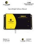
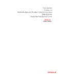
A803 INSTRUCTION MANUAL
________________________________________________________________________
A803 Manual Rev C, 2/2014
Page 1
10 Technology Drive
Peabody, MA 01960
Ph: 978-818-6180
Fax: 978-818-6181
Web: www.intl-lighttech.com
© 2011 International Light Technologies
For most current specifications and instructions, please visit our website:www.intl-lighttech.com
All Rights Reserved.
No part of this publication may be reproduced or transmitted in any form or by any
means, electronic or mechanical, including photocopying, recording, or any
information storage and retrieval system, without permission in writing from the
copyright owner. Requests should be made through the publisher.
A803 Manual Rev C, 2/2014
Printed in the United States of America
Page 3
Contents
1. System Set up
....................................................................................5
1.1 ILT1700 Set Up: ..................................................................................5
1.1.1 Power Settings.......... .........................................................................5
1.1.2 Power Cord ........................................................................................5
1.1.3 Select AC Power Source ....................................................................5
1.1.4 USB Cable........ ..................................................................................5
1.1.5 Sensor Input Port..................................................................................5
1.1.6 Accessory Input Port............................................................................5
1.1.7 Turn Power on......................................................................................5
1.1.8 System Optimization ….......................................................................6
1.1.9 Set Up ILT1700 calibration Factor…...................................................6
1.1.10 Bias Selection….................................................................................6
1.1.11 Installing Labview drivers for ILT1700….........................................6
1.1.12 Zero ILT1700…..................................................................6
1.2 A803Set Up..…......................................................................................6
1.2.1 Accessory Cable..................................................................................6
1.2.2 Sensor Input Cable..............................................................................6
1.2.3 Detector Connection............................................................................6
1.2.3 USB Cable...........................................................................................6
2. Software Initialization...............................................................................7
2.1 SOFTDAQ Set Up:.................................................................................7
2.1.1 Computer Set Up .................................................................................7
2.1.2 Software Installation ............................................................................7
2.2 Hardware Set Up:....................................................................................7
2.2.1 ILT1700 USB Cable.............................................................................7
2.2.2 A803 USB Cable..................................................................................7
2.3 Initializing SOFTDAQ:...........................................................................7
2.3.1 Run Executable ....................................................................................7
2.3.2 Select ILT1700 COM Port & Baud Rate .............................................7
2.3.2.1 Com Port Error...................................................................................7
2.3.1 SOFTDAQ Error..................................................................................7
2.3.2 USD Device Error ...............................................................................7
2.3.3 Enter Activation Code........................... ...............................................8
3.0 Turn On Your Light Source......................................................................8
A803 Manual Rev C, 2/2014
Page 4
4. Taking a Measurement in Software Mode...................................................8
4.1 Begin to Measure:......................................................................................8
4.1.1 User Interface Description......................................................................9
4.1.2 Select Channels to Measure....................................................................9
4.1.3 Data Acquisition Settings.......................................................................9
4.1.3.1 Set/Store Detector Sensitivity Factors (CalFactors).................10
4.1.3.2 Enter Number of Scans.............................................................10
4.1.3.3 Enter Value for Scan Delay.......................................................10
4.1.3.4 Chart History Length Selection.................................................10
4.1.3.5 Automatic Data Logging (Optional).........................................10
4.1.3.6 Selecting Automatic Data Log FilePath & File Type................10
4.1.4 Take a Measurement ..............................................................................11
4.1.4.1 Zero the Detector.........................................................................11
4.1.4.2 Set Measurement Mode........................ ......................................11
4.1.4.3 Data Display Options..................................................................11
4.1.4.4 Initiate a Scan/Display a Measurement ......................................12
4.1.7.4.1 Start Data Logging....................................................................12
4.1.7.4.2 Continuous Data Logging.........................................................12
4.1.7.4.3 Stop Data Logging (Optional)...................................................12
4.1.7.4.4 Hold Function (Optional) .........................................................12
5.0
Manual Mode …......................................................................................12
5.1.0 Set up...............................................................................................12
5.1.1 Set/Store Detector Sensitivity Factors.............................................12
5.1.2 Select Active Channel......................................................................13
5.1.3 Sensitivity Factor Selection ….........................................................13
5.1.4 Bias Selection...................................................................................13
5.1.5 Take A Measurement........................................................................13
6.
Warranty and Service …............................................................................13
NOTE: The software associated with the A803 product is intended for use with the following operating
systems: Windows XP, Windows Vista, Windows 7
A803 Manual Rev C, 2/2014
Page 5
1.0 SYSTEM SET UP (You will need a small philips and flat head screw driver and a USB cable to
proceed)
1.1
ILT1700 Set up
ILT1700 Back Panel
1.1.1
Power Settings
Switch AC voltage selector switch to 220 or 115 VAC as
applicable. Select 115 VAC for use on power systems between
90 and 130 VAC (JP, US, CA). Select 230 VAC for
use on power systems between 180 and 260 VAC (EC, AU).
1.1.2
Power Cord
(CHECK POWER SETTING BEFORE CONNECTION TO
PREVENT DAMAGE) Connect power cord to power input
then into main wall socket. The standard male power plug on
the back of theILT1700 accepts power cords from many different countries
and power systems.
Sensor cable input
Accessory cable input
1.1.3
Optional AC Power Source
If you have purchased the A417 Battery pack or installed 6 C-size (sold separately)
Source AC/BAT switch
RECHARGABLE (ONLY) batteries and have fully charged them for initial use,
Power Cord input
you may switch the AC/BAT selector to BAT position for operation using
USB port
an alternate current power supply. The internal NiMH batteries
Power
setting
will automatically recharge whenever the ILT1700 is plugged into an external
power supply and set on the BAT position. (Using non-rechargeable batteries is
not recommended and can damage internal components if charged or left in for extended periods)
1.1.4
USB cable
Connect customer supplied USB cable to the USB port on the ILT1700, but do not connect to the computer at this time.
1.1.5
Sensor input Port
Connect the Male end of the Male to Female Sensor Input cable to the sensor input port.
1.1.6
Accessory input Port
Connect the A402-A 24 pin Card Edge end of the Accessory cable to the “Accessory Input” connector on the back of the
ILT1700 Radiometer.
ILT1700 Front Panel
1.1.7
Turn Power On
Press POWER switch. AC LED indicator should be illuminated
1.1.8
System optimization (optional) 2, 4 or 8 readings per second
The ILT1700 defaults to updating the display every 500 ms (2 reading per
sec) and should always be turned off while in this mode. To change the rate
at which the ILT1700 measures and displays a reading, press FACTOR
SHIFT/DATA DISPLAY button until Factor Shift LED is illuminated, then press
SET 100% button. Use the FACTOR SELECT button to choose between
Factor Shift/Data Display
2, 4, or 8 readings per second. When set, click SET 100%, then DATA DISPLAY. Factor Select
Set 100%
Prior to powering off the ILT1700, please verify the mode has been set to 2 readings per sec.
A803 Manual Rev C, 2/2014
Page 6
1.1.9
Set ILT1700 Sensitivity Factor
Set the ILT1700 sensitivity factor to read 1.000x10 0 using the following
procedure:
a. Press FACTOR SHIFT button on the front of ILT1700 until the
FACTOR SHIFT LED is illuminated.
b. Press FACTOR SELECT button until register “0” appears in window
above the button. (other channels may be used if preferred)
c. Use MSD & LSD buttons to change the display to read 1.000.
d. Use the EXP button to change the display to read 0.
Once completed, press the FACTOR SHIFT/DATA DISPLAY button to return
the ILT1700 to DATA DISPLAY mode, verifying the DATA DISPLAY LED is
illuminated.
MSD LSD
EXP
Factor /Data
Factor Select
5V bias
1.1.10 Bias Selection
Press 5V Bias button if you are using a vacuum photodiode type detector (SED240,SED220,SED185), or for flash
measurements. It is recommended not to connect a combination of vacuum photodiode type detectors with non biased
detector types as they can be damaged by the 5V Bias. (such as SED623, SED005 and others)
1.1.11 Installing complimentary Labview Drivers for theILT1700
The ILT1700 comes with a CD containing software and the ILT1700 instruction manual. If you have not already
installed the software and tested the ILT1700 USB port, you should follow these steps before you proceed. If you have
already used the ILT1700 and the LabVIEW drivers, you can skip this step.
a. Insert the CD labeled ILT1700 – USB Virtual Instrument Driver and follow the installation instructions.
b. Upon plugging the ILT1700 into a USB port on a PC, the computer’s operating system will detect the instrument and will
need to be pointed to the directory where you have extracted the driver .zip file in order to properly install the driver. The installer will
install a virtual Com port for the new device.
c. Make a note of which com port you selected as you will need this information when running the LabVIEW® drivers._________
d. Disconnect the ILT1700 and unplug from the computer.
1.1.12 ZERO the ILT1700
Before system connections you want to establish a good dark zero for the ILT1700. With everything unplugged, press
the zero button and wait a few seconds for the meter to return to DC.
A803 Back Panel
1.2
A803 Set Up
1.2.1
Accessory Cable
Connect the A402-A Accessory cable to the “Accessory Input”
connector on the back of the A803.
1.2.2
Sensor Input Cable
Connect the female end of the Sensor Input cable to the
connector labeled “ILT1700 Sensor Input” on the back of the A803.
1.2.3
Detector Channel 1-4, or 1-8
Connect at-least one Detector to the Sensor connector ports.
Sensor cable input
USB cable input
Accessory cable input
1.2.4
USB cable
Connect USB cable to the USB port on the A803, but do not connect to the computer at this time.
A803 Manual Rev C, 2/2014
Page 7
2.0
SOFTDAQ Installation
2.0.1
Computer Set Up
Verify that 2 USB2 port connections are available on the computer/laptop that is being used. Power on the computer/laptop. Verify
that a SOFTDAQ icon is not already visible in the desired location. If software is already installed proceed to 2.1
2.0.2
Software Installation
If software is not installed, insert the software disk into the disk drive. Double-click on the SETUP.EXE file to install the SOFTDAQ
program onto the computer/laptop. Follow the on screen instructions to install SOFTDAQ.
2.1
Hardware Setup
2.1.1
ILT1700 USB Cable
Connect the USB cable from the ILT1700 to an unused USB port on the computer and turn on the ILT1700. Wait 20-30 seconds for it
to initialize. It is very important that the ILT1700 is set up properly before you proceed. Failure to register the ILT1700 first can cause
trouble with A803 recognition in the next steps which may force you to have to re-boot your system.
2.1.2
A803 USB Cable
Connect the USB cable from the A803 to an unused USB port on the computer and
wait 20-30 seconds for it to initialize. Verify that the green USB LED indicator light
is illuminated on the rear of the A803.
2.2
Initializing SOFTDAQ
2.2.1
Run the Executable
Double-click the SOFTDAQ icon to open and run the software.
Green USB LED
Indicator
2.2.2
Select ILT1700 COM Port, Baud Rate, and error messages
When prompted, select the appropriate ILT1700 COM port with a Baud rate of 4800 and click OK. Wait for message verifying
SOFTDAQ INITIALIZATION SUCCEEDED, and then verify that the DC function LED on the front panel of the A803 is
illuminated and that no Active Channel LEDs should be illuminated.
Manual mode channel
DC Function LED
illuminated
selection.(not available in
all revisions)
No Channel LEDs
illuminated
2.2.2.1 Error COM port screen returns after selection
Verify your COM port selection, right-click MY COMPUTER, and select PROPERTIES. Then select Device Manager under the
HARDWARE tab and scroll down to view PORTS. You can plug in and unplug the ILT1700 USB cable to see which COM Port is
being registered.
2.2.2.2 Error SOFTDAQ initialization failed. Start over at 2.1. You may need to restart your computer.
2.2.2.3 Error USB Device Not Recognized
When connecting the A803 USB cable to the computer, some older systems may have difficulty registering the A803. This
error can be troublesome. You may need to start over at step 2.1 and be sure to plug in the ILT1700 USB cable first and wait
patiently. You may need to try switching ports until both devices are registered. You may also want to try a newer computer
if the laptop you are using continues to display this error message. Some older computers do not like to run two Labview
A803 Manual Rev C, 2/2014
Page 8
drivers at the same time.
2.2.3
Enter Activation Code for first time use
After selecting the ILT1700 COM port and succeeding with initialization , you may be prompted with a warning that states YOUR
SOFTWARE LICENSE IS SET TO EXPIRE IN 30 DAYS. Select ENTER ACTIVATION CODE from the pop-up box and enter the
activation code, which can be found on the outside of the installation disk.
Verify that SOFTDAQ opens in CHART view,
per the following image:
3.0
Turn on light source to be measured
3.1.1
Turn on the light source to be measured and allow the appropriate warm up time as necessary.
4.0
Taking Measurements
Section 1.0 Hardware Initialization and Section 2.0 Software Initialization will be completed prior to continuing with this section.
4.1
Set Software Parameters
The following sections will describe how to set up SOFTDAQ to measure
NOTE: All items and their functions are described in the following sections
A803 Manual Rev C, 2/2014
Page 9
4.1.1
User Interface Description
Channel plot legend
Top Menu
Stop Data Logging
Continuous Data Logging
Start Data Logging
Hold function
Integrate function
DC Signal function
Zero function
Data Acquisition Settings
Print function
Save current data
Channel selection tool
Function indicators
(only used to indicate
whether a specific
function is active, not
used to actually initiate
a function)
Chart Area
Current log file name
Current data scan settings
Data Acquisition indicator
4.1.2
Select Channels
Using the channel selection tool (see Section 4.1.1), select the channels you wish to be active during next measurement. The user can
select up to 8 channels to scan (4 if using A803-4).
4.1.3
Data Acquisition Settings
Press the Data Acquisition Settings button on the user interface (see Section 4.1.1) to open the Data Acquisition Settings box. See
image below for setting up the acquisition.
4.1.3.1 Set/Store Sensitivity Factors (CalFactors)
In the right side section of the Data Acquisition Settings box, enter detector serial numbers & sensitivity factors from each
detectors' calibration certificate in the appropriate box starting with channel 1 at the top for all detectors being used. Using a
cal factor of 1E+0 will allow measurement in current (amps).
A803 Manual Rev C, 2/2014
Page 10
Channels 5-8
are not visible if
using A803-4
4.1.3.2 Enter Number of Scans
Select the number of scans for each channel/detector being measured. The software will capture 1 measurement per channel
per scan for data logging.
4.1.3.3 Enter Value for Scan Delay
Select the desired value (in seconds) for delay between scans. For the most accurate results, a scan delay of at least 2 seconds
is recommended. Longer delays are recommended if values are changing over many dynamic ranges. This allows the ILT1700
time to discharge the capacitor when changing from a very high currents down to a very low currents. (ie decrease from
30,000 lux to 100 lux)
4.1.3.4 Chart History Length Selection
Select the desired Chart History Length which forces the software to only plot out the selected number of samples on the user
interface chart. If the Number of Scans exceeds the Chart History Length, data will still be logged for all scans, but only the
number of samples selected for chart history length will be visible on the user interface chart.
4.1.3.5 Automatic Data Logging (Optional)
The user has the option of checking the box labeled “Automatically log data after scan”. If the user does not want to
automatically log the data following the scan, skip to Section 4.1.5. Otherwise, proceed to 4.1.4.6
4.1.3.6 Selecting Automatic Data Log File Path and File Type (Optional)
If user selects to automatically log the data after the scan, use the “Browse” icon to select the file path the user wants the data
to be saved in. Then use the “Save Format” drop-down menu to select an output .TXT file or .XLS file.
Click the OK button when the user has completed inputting all Data Acquisition Settings. To return to the user interface
without inputting data logging settings, click CANCEL.
A803 Manual Rev C, 2/2014
Page 11
NOTE: User can also access the Data Acquisition Settings by choosing SETUP → DATA LOG SETTINGS from the Top menu
of the user interface in Section 4.1.1, or by clicking on the dialog boxes for Number of Scans of Scan Delay at the bottom of
the user interface seen in Section 4.1.1.
4.1.4
Taking a Measurement
Follow the steps below to take a measurement using SOFTDAQ software.
4.1.4.1 Zero the Detectors
A dark zero is the recommended zero for the ILT1700/A803. To perform a dark
zero you must cover all of the sensors that have been activated with an opaque
object and wait a few second to allow the capacitor in the ILT1700 to discharge
fully. Press the zero button in the software and wait until the zero is complete.
Note: It is also possible to do an ambient zero when using the A803 provided the
readings are similar on all selected channels. An ambient zero will subtract the current reading,
from all future readings. Ambient zero can be a cause of errors, if there is not a
uniform ambient condition for all of the selected sensors.
ZERO Function
NOTE: After initial software boot-up, the user will not be able to start scanning data without first performing the ZERO
function. User will be prompted with a dialog box stating that the system must be zero'd prior to starting a scan.
4.1.4.2 Set Measurement Mode
Select measurement function by pressing either D.C. (signal) function
button or Integrate function button for continuous or integrated readings
from user interface in Section 4.1.1. Remember Integrate mode will sum
up the signal over a specific integration time and D.C. mode will read
the average steady state light levels.
DC Function
Integrate Function
4.1.4.3 Data Display Options
In the Top Menu (see Section 4.1.1), select VIEW and choose the desired view for measurement readings. User has the option of
viewing the CHART, which plots the values in an auto-populated graph, or viewing a TABLE which auto-populates the table with the
measurements for each channel during a scan.
Example TABLE view
Example CHART view
4.1.4.4 Initiate a Scan/Display a Measurement
The user has 2 options for starting a data scan, which are both described below. Read both descriptions before deciding which option
is best suited for the users' application.
A803 Manual Rev C, 2/2014
Page 12
4.1.4.4.1 Start Data Logging
Click the Start Data Logging button on the user interface (see Section 4.1.1)to start reading
the selected channels (from channel selection tool on user interface) based on the user
defined data acquisition settings from Section 4.1.4,specifically Number of Scans, Scan Delay,
and Chart History Length.
Start Data Logging Function
Once the software has measured and logged detector data on each user-selected channel for the number of user-selected scans, and if
the user selected the “Automatic Data Log” function (see Sections 4.1.4.5-4.1.4.6), scan data will be stored in the designated file path
as the designated file type.
NOTE: Any scan data generated from new scans will be added to the already existing file and will NOT overwrite it. If scanning for
the first time upon opening/initializing the SOFTDAQ software, user will be prompted to set the ILT1700 calibration factor to 1.
4.1.4.4.2 Continuous Data Logging
Click the Continuous Data Logging button on the user interface (see Section 4.1.1) To start reading the
selected channels (from channel selection tool on user interface). Continuous Data Logging will
continuously measure each selected channel and ignore the Number of Scans chosen by the user.
Pressing the Stop Data Logging button will the system stop the Continuous Data logging function.
Continuous Data
Logging Function
Once the software has measured and logged detector data on each user-selected channel for the number
of user-selected scans, and if the user selected the “Automatic Data Log” function, scan data will be
stored in the designated file path as the designated file type.
NOTE: Any scan data generated from new scans will be added to the existing file and will NOT overwrite it.
4.1.4.4.3 Stop Data Logging (Optional)
At any point during a scan, the user has the option to stop the scan by pressing the Stop Data Logging button.
Stop Data
Logging Function
4.1.4.4.4 Hold Function (Optional)
At any point during a scan, the user has the option to Hold, or freeze, the scan by pressing the HOLD function
button from the user interface, which will cause the software to display the same value at
each channel until the user sets a new measurement mode.
4.1.5
Hold function
Manual Data Save (Optional)
After a scan, the user has the option of saving the specific scan data by pressing the Save Current
Data button from the user interface (see Section 4.1.1). After clicking the button, the user will
be prompted to name the file and select a file path.
Save current data
5.0 TAKING A MEASUREMENT IN MANUAL MODE
5.1.0 SET UP:
Select/Connect Detectors; Determine the type and amount of detectors to be used (4 or 8 detectors can be connected to the A803
Multiplexer). Connect the applicable detectors to the channel connectors on the back of the A803. Detector arrangement will be
determined by the user.
5.1.1 Set/Store Detector Sensitivity Factors
Using ILT1700, enter sensitivity factors from each detectors' calibration certificate using the following procedure:
a. Press FACTOR SHIFT button on the front of ILT1700 until the FACTOR SHIFT LED is illuminated.
b. Press F ACTOR SELECT button until register “1” appears in window above the button.
c. Enter sensitivity factor for the detector connected to Channel1 by using MSD, LSD buttons to change reading display & EXP
button to change exponent. Use the FACTOR SELECT button to increment to the desired register (1-8) and use the above procedure
to store sensitivity factors for detectors in their respective channels. NOTE: The ILT1700 has the capability to store sensitivity factors
in 10 registers (0-9), but recommended use is to correlate the register with the channel and the detector connected to that channel.
A803 Manual Rev C, 2/2014
Page 13
Registers “0” and “9” can be used for extra sensitivity factors to be used at the discretion of the user. After storing all applicable
sensitivity f actors, click the FACTOR SHIFT/DATA DISPLAY button until the DATA DISPLAY LED is illuminated.
5.1.2 Select Active Channel
Use the Active Channel buttons on the front of the A803 to scroll through channels 1-8 and select which channel to measure from.
Verify a detector is connected to the active channel once selected.
5.1.3 Sensitivity Factor Selection
Once the Active Channel has been selected, chose the appropriate sensitivity factor for that specific channel/detector by pressing the
FACTOR SHIFT/DATA DISPLAY button until the FACTOR SHIFT LED is illuminated. Select the applicable register (1-8) by using
the FACTOR SELECT button. Select register 1 if active channel is 1, select register 2 if active channel is 2, up to channel 8.
After selecting appropriate sensitivity factor, press the FACTOR SHIFT/DATA DISPLAY button until the DATA DISPLAY LED is
illuminated. The ILT1700 is now ready to display data from the detector connected to the active channel.
5.1.4 Bias Selection
Press 5VBias button if you are reading a channel that is using a vacuum phototube detector (SED240 or SED220), or for flash
measurements with the silicon diodes SED100 or SED033.
5.1.5 Take a Measurement
Follow the steps below to take a measurement in manual mode.
5.1.5.1 Set Measurement Mode
Select measurement function by pressing either D.C. (signal) button or INT button for continuous or integrated readings. Remember
IN T will sum up the signal over that integration time and D.C. mode will read the average steady state light levels.
5.1.5.2 Zero the Detector
For a dark zero, cover the active channel detector with opaque object, wait ten seconds and press ZERO button. For ambient zero,
simply press zero button for uncovered active channel detector for over one second and release. (will subtract current zero from all
future readings)To return to internal zero, unplug the detector attached to the active channel and press zero. Uncover the detector after
zeroing.
5.1.5.3 Display Measurement
At this point, the detector that is connected to the Active Channel will be measuring, and outputting the measurement to the ILT1700
display. For taking measurements on separate channels, simply use the Active Channel buttons to select the desired channel/detector,
making sure that the correct sensitivity factor has also been selected (see Section 3.1.4 for sensitivity factor selection).
5.1.5.4 Hold Function (Optional)
User has the option of pressing the HOLD button on the ILT1700 to freeze the reading display with its current value at any point of a
measurement.
5.1.5.5 Integrate Function (Optional)
User has the option of pressing the INT button on the ILT1700 which continuously integrates the detector reading every second. For
more information on the Integrate function, refer to Section 3.0 of the ILT1700 Instruction Manual. A803 Multiplexer Instruction
Manual Rev A
6. Warranty and Service
This ILT product is warranted against defects in material and workmanship for a period of one year from the date of shipment. During
the warranty period, ILT will, without charge, repair or replace, at its discretion, the defective product or component parts. For
warranty service or repair, this product must be returned to International Light Technologies. For products returned under warranty,
the Buyer shall prepay shipping charges (including shipping charges, duties, and taxes for products returned to ILT from another
country), and ILT will pay for shipping charges to return the product to the Buyer. There is no regular maintenance required for the
A803. Annual recalibration is recommended for the ILT1700 and all sensors/detector configurations. Please contact our customer
service dept. at 978 818 6180 x 227, by email at [email protected] and online at http://www.intl-lighttech.com/services
/return-material-authorization. All items returned for service require an RMA to prevent delay and assure the accuracy of service.
ILT offers a full line of light measurement system and lighting products including LED signage, LED Lighting, and specialty light
sources. Please take a moment to visit our website to learn more: http://www.intl-lighttech.com/
A803 Manual Rev C, 2/2014
Page 14