1
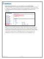
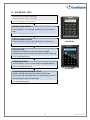
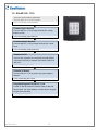
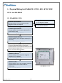
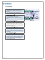
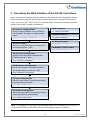
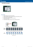
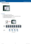
Quick Start Guide
GV-AS / EV Controller
Thank you for purchasing GV-AS / EV Controller. This guide is designed to assist the new user in
getting immediate results from the controllers. For advanced information on how to use the GVAS100 / 1010 / 110 / 1110 / 120 / 210 / 2110 / 410 / 4110 / 810 / 8110 and GV-EV48, please
refer to GV-AS / EV Controller User's Manual on Software CD.
ASEV-QG-D
© 2015 GeoVision, Inc. All rights reserved.
Under the copyright laws, this manual may not be copied, in whole or in part,
without the written consent of GeoVision.
Every effort has been made to ensure that the information in this manual is
accurate. GeoVision, Inc. makes no expressed or implied warranty of any kind
and assumes no responsibility for errors or omissions. No liability is assumed
for incidental or consequential damages arising from the use of the information
or products contained herein. Features and specifications are subject to
change without notice.
Note: No memory card slot or local storage function for Argentina.
GeoVision, Inc.
9F, No. 246, Sec. 1, Neihu Rd.,
Neihu District, Taipei, Taiwan
Tel: +886-2-8797-8377
Fax: +886-2-8797-8335
http://www.geovision.com.tw
Trademarks used in this manual: GeoVision, the GeoVision logo and GV
series products are trademarks of GeoVision, Inc. Windows and Windows XP
are registered trademarks of Microsoft Corporation.
April 2015
Contents
Contents...........................................................................................................................i Important Note for Maintaining Power Supply.................................................................. ii GV-AS Controller Quick Start Guide............................................................................... 1 1. Basic Setup for GV-AS100 / 1010 / 110 / 1110 / 120 ................................................. 1 1.1 GV-AS100 / 1010 ............................................................................................. 2 1.2 GV-AS110 / 1110 ............................................................................................. 3 1.3 GV-AS120 ........................................................................................................ 4 2. Physical Wiring for GV-AS210 / 2110 / 410 / 4110 / 810 / 8110 and GV-EV48 .......... 5 2.1 GV-AS210 / 2110 ............................................................................................. 5 2.2 GV-AS410 / 4110 / 810 / 8110.......................................................................... 6 2.3 GV-EV48 .......................................................................................................... 7 3. Accessing the Web Interface of the GV-AS Controllers ............................................. 8 4. Setting GV-AS Controller on GV-ASManager ............................................................ 9 5. Optional Devices for GV-AS100 / 110 / 120..............................................................10 5.1 Physical Wiring of GV-ASBox and GV-ASNet .................................................11 5.2 Accessing the Web Interface of GV-AS100 / 110 / 120....................................12 April 20, 2015
i
Important Note for Maintaining Power Supply
To make sure GV-AS / EV Controllers can function properly during a power outage, be sure
to replace the internal battery on the controllers when needed. It is also recommended to
install a backup battery for compatible GV-AS Controllers.
Refer to the following sections in GV-AS Controller User Manual for instructions on how to
install a backup battery:
z
GV-AS100 / 110 / 120 through GV-ASBox: See 9.1.4.F Connecting Backup Battery.
z
GV-AS100 / 110 / 120 through GV-ASNet: See 9.2.4.F Connecting Backup Battery.
z
GV-AS210 / 2110: See 4.2.4 Connecting Backup Battery
z
GV-AS410 / 4110 / 810 / 8110: See 5.2.4 Connecting Backup Battery
z
GV-EV48: See 6.2.3 Connecting Backup Battery.
Replaceable Button Cell (GV-AS100 / 2110 / 4110 / 8110)
For GV-AS100 / 2110 / 4110 / 8110, you can replace the battery on your own when you see
low battery messages and icons in GV-ASManager.
Note: Make sure the plastic insulation film under the battery is removed when using GVAS100 / 2110 / 4110 / 8110 for the first time. The low battery messages and icons will appear
if the plastic film is not removed.
ii
April 20, 2015
Built-in Battery (GV-AS1010 / 110 / 1110 / 120 / 210 / 410 / 810 & GV-EV48)
When the controller runs out of battery, the local time on the controller will be reverted back
to 1999/12/31. The controller time can be found on the Web interface of the controller on the
Time Setting page and in the Access Monitor / Alarm Monitor / Event Monitor of GVASManager.
When you see the controller year shown as 1999 or 2000, disconnect the controller from
power and reconnect it to power. If the year is still shown as 1999 or 2000, the controller
battery needs to be replaced. When this occurs, connect the controller to a backup battery
and maintain connection with GV-ASManager at all times. When connected to GVASManager, the controller’s time will be synchronized with GV-ASManager’s time.
April 20, 2015
iii
GV-AS Controller Quick Start Guide
This guide lists the basic steps required to set up a GV-AS Controller. For detailed
instructions, refer to the section number listed below each step.
1. Basic Setup for GV-AS100 / 1010 / 110 / 1110 / 120
This section covers the basic settings required to start running GV-AS100 / 1010 / 110 / 1110
/ 120. For more settings on GV-AS100 / 110 / 120, refer to 5. Optional Devices for GV-AS100
/ 110 / 120. The section numbers listed here refers to the GV-AS Controller User Manual.
April 20, 2015
1
1.1 GV-AS100 / 1010
Connect card readers (Optional)
Connect AS100 / 1010 to a reader.
1.2.1 Connecting Card Readers
Connect input devices
Connect AS100 / 1010 to input devices (Ex: a push button to
exit).
1.2.2 Connecting Input Devices
Connect output devices
Connect AS100 / 1010 to output devices (Ex: a door lock).
GV-AS100
1.2.3 Connecting Output Devices
Connect to PC
Connect the controller to a computer through RS485
connection (AS100) or network connection (AS100 & AS1010).
1.2.4 Connecting the PC
Connect to Power
Connect AS100 / 1010 to power using the supplied adaptor.
1.2.5 Connecting the Power
GV-AS1010
Programming the GV-AS100 / 1010
Create a Master Card (AS100) or Enroll / Delete Card
(AS1010) to add and delete cards. For other settings, use the
built-in keypad to type the commands.
1.3 Programming Mode
2
April 20, 2015
1.2 GV-AS110 / 1110
Connect card readers (Optional)
Connect AS110 / 1110 to a reader..
2.2.1 Connecting Card Readers
Connect input devices
Connect AS110 / 1110 to input devices (Ex: a push
button to exit).
2.2.2 Connecting Input Devices
GV-AS110 / 1110
Connect output devices
Connect AS110 / 1110 to output devices (Ex: a door
lock).
2.2.3 Connecting Output Devices
Connect to PC
Connect the controller to a computer through RS485
connection (AS110) or network connection (AS110 &
AS1110).
2.2.4 Connecting the PC
Connect to Power
Connect AS110 / 1110 to power using the supplied
adaptor.
2.2.5 Connecting the Power
Programming the GV-AS110 / 1110
Create an Enroll Card and a Delete Card to add and
delete cards. For other settings, use the built-in keypad
to type the commands.
2.3 Programming Mode
April 20, 2015
3
1.3 GV-AS120
Connect card readers (Optional)
Connect AS120 to a reader through Wiegand
interface.
3.2.1 Connecting a Wiegand Reader
Connect input devices
Connect AS120 to input devices (Ex: a push
button to exit).
3.2.2 Connecting Input Devices
Connect output devices
GV-AS120
Connect AS120 to output devices (Ex: a door
lock).
3.2.3 Connecting Output Devices
RS485 Connection
Connect to PC
3.2.4.A RS-485 Connection
Connect AS120 to a computer through RS485
connection or network connection.
Network Connection
3.2.4.B Network Connection
Connect to Power
Connect AS120 to power using the supplied 12V
DC adaptor.
3.2.5 Connecting the Power
Add and delete cards
Create an Enroll Card and a Delete Card to add
and delete cards.
3.3 Programming Mode
4
April 20, 2015
2. Physical Wiring for GV-AS210 / 2110 / 410 / 4110 / 810 /
8110 and GV-EV48
2.1 GV-AS210 / 2110
Wiegand
Connect card readers
4.2.1.A Wiegand Readers
Connect AS210 / 2110 to readers through
Wiegand or RS-485 interface.
RS485
4.2.1.B RS-485 Readers
Connect input devices
Connect AS210 / 2110 to input devices (Ex: a
push button to exit).
4.2.2 Connecting Input Devices
Connect output devices
Connect AS210 / 2110 to output devices (Ex: a
door lock).
4.2.3 Connecting Output Devices
Connect Backup Battery (Optional)
Connect AS210 / 2110 to backup battery in case
the main power supply fails.
4.2.4 Connecting Backup Battery
Connect to Power
Connect AS210 / 2110 to power using the
supplied 12V DC adaptor.
4.2.5 Connecting the Power
Connect to PC
Connect AS210 / 2110 to a computer to access
its Web interface and connect with GVASManager.
4.2.6 Connecting the PC
April 20, 2015
5
GV-AS210 / 2110
2.2 GV-AS410 / 4110 / 810 / 8110
Wiegand
Connect card readers
Connect AS410 / 4110 / 810 / 8110 to readers
through Wiegand or RS-485 interface.
5.2.1.A Wiegand Readers
RS485
5.2.1.B RS-485 Readers
Connect input devices
Connect AS410 / 4110 / 810 / 8110 to input
devices (Ex: a push button to exit).
5.2.2 Connecting Input Devices
Connect output devices
Connect AS410 / 4110 / 810 / 8110 to output
devices (Ex: a door lock).
5.2.3 Connecting Output Devices
Connect Backup Battery (Optional)
Connect AS410 / 4110 / 810 / 8110 to backup
battery in case the main power supply fails.
5.2.4 Connecting Backup Battery
Connect to Power
Connect AS410 / 4110 / 810 / 8110 to power
using the supplied 12V DC adaptor.
5.2.5 Connecting the Power
Connect to PC
Connect AS410 / 4110 / 810 / 8110 to a
computer to access its Web interface and
connect with GV-ASManager.
5.2.6 Connecting the PC
GV-AS410 / 4110 / 810 / 8110
6
April 20, 2015
2.3 GV-EV48
Connect card readers
Connect EV48 to readers through RS-485
interface.
6.2.1 Connecting RS-485 Card Readers
Connect output relay
Connect EV48 output relays to the
corresponding floor on the elevator control
panel.
6.2.2 Connecting Output Relay
GV-EV48
Connect Backup Battery (Optional)
Connect EV48 to backup battery in case the
main power supply fails.
6.2.3 Connecting Backup Battery
Connect to Power
Connect EV48 to power using the supplied 12V
DC adaptor.
6.2.4 Connecting the Power
Connect to PC
Connect EV48 to a computer to access its Web
interface and connect with GV-ASManager.
6.2.5 Connecting the PC
April 20, 2015
7
3. Accessing the Web Interface of the GV-AS Controllers
After connecting the required wires and cables for the following GV-AS Controllers, access
the Web interface of the GV-AS Controller to define the devices connected: GV-AS1010 /
1110 / 210 / 2110 / 410 / 4110 / 810 / 8110 and GV-EV48. The section numbers listed here
refers to the GV-AS Controller User Manual.
Set network configurations
Assign a static IP address or set up DDNS to
map a dynamic IP address to a static domain
name.
Chapter 7 Installing on a Network
Static IP address
7.1 Fixed IP connection
Dynamic IP address
7.2 DHCP Connection
Set Wiegand readers
8.2.8 Wiegand Function
Set card readers
Define the connected readers by selecting the
corresponding doors / gates.
Set RS485 or TCP/IP readers
8.3.1 Extended Reader
Set Function Configuration
Specify the function and the authentication
mode for each door / gate.
8.2.1 Function Configuration
Set Parameter Configuration
Set the door operation for different situations
and enable alarms for each door / gate.
8.2.2 Parameter Configuration
Set Input Configuration
Name the input devices connected and set the
input type and input function.
8.2.6 Input Configuration
Set Output Configuration
Name the output devices connected and set the
output type, function and conditions.
8.2.7 Output Configuration
Note: The Wiegand Function and Output Settings pages are not available for GV-AS1010 /
1110 and GV-EV48. For GV-EV48, the Input Setting page is also not available.
8
April 20, 2015
4. Setting GV-AS Controller on GV-ASManager
After setting up the Web interface, connect the GV-AS Controller to a GV-ASManager.
Through GV-ASManager, you can set up the doors and enroll cards. The section numbers
listed here refers to the GV-ASManager User Manual.
Install GV-ASManager
Install GV-ASManager from the supplied
software DVD.
Chapter 2 Installation
Set GV-AS Controllers
Establish connection between the controllers
and GV-ASManager.
4.2.1 Configuring a Controller
Set doors / gates
Enable the doors on the controllers and
configure settings as needed.
4.2.2 Configuring a Door
Add cards to GV-ASManager
Enroll cards into GV-ASManager and define the
card types.
4.3 Adding Cards
April 20, 2015
9
5. Optional Devices for GV-AS100 / 110 / 120
To access GV-AS100 / 110 / 120 on a network, an optional device GV-ASBox or GV-ASNet
is required. GV-ASBox also supports connection with additional input devices, output devices
and readers through Wiegand interface and RS-485 interface. GV-ASNet supports additional
readers through RS-485 connection.
You will need to first complete the physical wiring of GV-ASBox or GV-ASNet before
accessing the Web interface. After the controller is installed on a network, GV-AS100 / 110 /
120 can also connect with GV-ASManager for advanced settings. Refer to 4. Setting GV-AS
Controller on GV-ASManager for details.
10
April 20, 2015
5.1 Physical Wiring of GV-ASBox and GV-ASNet
The section numbers listed here refers to the GV-AS Controller User Manual.
Physical Wiring of GV-ASBox
Physical Wiring of GV-ASNet
Connect GV-AS100 / 110 / 120
Connect GV-AS100 / 110 / 120
Connect GV-ASBox with GV-AS100 / 110 / 120.
9.1.4.A Connecting GV-AS100 / 110 / 120
Connect GV-ASNet with GV-AS100 / 110 / 120.
9.2.4.A Connecting GV-AS100 / 110 / 120
Connect a Wiegand reader
Connect readers through RS-485
GV-ASBox supports connection with one
Wiegand reader.
Connect GV-ASNet with readers through RS485 interface.
9.1.4.B Connecting a Wiegand Reader
9.2.4.B Connecting GV-Readers and GV-GF
Fingerprint Readers
Connect readers through RS-485
Connect Backup Battery (Optional)
Connect GV-ASBox with readers through RS485 interface.
9.1.4.C Connecting GV-Readers and GV-GF
Fingerprint Readers
Connect GV-ASNet to backup battery in case
the main power supply fails.
9.2.4.C Connecting Backup Battery
Connect input devices
Connect to Power
Connect GV-ASBox to input devices (Ex: a
push button to exit).
Connect GV-ASNet to power using the supplied
12V DC adaptor.
9.1.4.D Connecting Input Devices
Connect to PC
Connect output devices
Connect GV-ASNet to a computer to access its
Web interface and connect with GV-ASManager.
Connect GV-ASBox to output devices (Ex: a
door lock).
9.1.4.E Connecting Output Devices
Connect Backup Battery (Optional)
Connect GV-ASBox to backup battery in case
the main power supply fails.
9.1.4.F Connecting Backup Battery
Connect to Power
Connect GV-ASBox to power using the supplied
12V DC adaptor.
Connect to PC
Connect GV-ASBox to a computer to access its
Web interface and connect with GV-ASManager.
April 20, 2015
11
5.2 Accessing the Web Interface of GV-AS100 / 110 / 120
The section numbers listed here refers to the GV-AS Controller User Manual.
Set network configurations
Assign a static IP address or set up DDNS to
map a dynamic IP address to a static domain
name.
Chapter 7 Installing on a Network
Set card readers
Set Wiegand readers (ASBox only)
9.3.2.A Function Setting
Define the connected readers by selecting the
corresponding doors / gates.
Set RS485 or TCP/IP readers
9.3.2.G Extended Reader
Set Function Settings
Specify the function and the authentication mode
for each door / gate.
9.3.2.A Function Setting
Set Parameter Settings
Set the door operation for different situations
and enable alarms for each door / gate.
9.3.2.B Parameter Settings
Set Input / Output Settings (ASBox only)
Name the input / output devices connected and
define the input / output sensors.
9.3.2.F In / Out Function
12
April 20, 2015