1
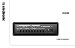
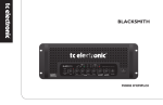
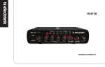
Classic450
USER’S MANUAL
1
2
3
4
5
6
7
8
9
10
11
12
14
Read these instructions.
Keep these instructions.
Heed all warnings.
Follow all instructions.
Do not use this apparatus near water.
Clean only with dry cloth.
Do not block any ventilation openings. Install in accordance with the
manufacturer’s instructions.
Do not install near heat sources such as radiators, heat registers, stoves, or other
apparatus (including amplifiers) that produce heat.
Do not defeat the safety purpose of the polarized or grounding-type plug. A
polarized plug has two blades with one wider than the other. A grounding type plug
has two blades and a third grounding prong. The wide blade or the third prong are
provided for your safety. If the provided plug does not fit into your outlet, consult an
electrician for replacement of the obsolete outlet.
Protect the power cord from being walked on or pinched, particularly at plugs,
convenience receptacles, and the point where they exit from the apparatus.
Only use attachments/accessories specified by the manufacturer.
12
Use only with the cart, stand, tripod, bracket,
or table specified by the manufacturer or sold with the apparatus. When
a cart is used, be careful when moving the cart/apparatus combination
to avoid injury from tip-over.
13
Unplug this apparatus during lightning storms or when not
in use for longer periods of time.
Refer all servicing to qualified service personnel. Servicing is required when the
apparatus has been damaged in any way, such as when a power supply cord or
plug is damaged, liquid has been spilled or objects have fallen into the apparatus,
or if the apparatus has been exposed to rain or moisture, does not operate
normally or has been dropped.
Warning!
• To reduce the risk of fire or electrical shock, do not expose this equipment to
dripping or splashing and ensure that no objects filled with liquids, such as vases,
are placed on it.
• This apparatus must be earthed.
• Use a three wire grounding type line cord like the one supplied with the product.
• Be advised that different operating voltages require the use of different types of line
cord and attachment plugs.
• Check the voltage in your area and use the correct type. Please refer to the
following table:
•
•
•
•
•
Voltage
Line plug according to standard
110-125V
UL817 and CSA C22.2 no 42.
220-230V
CEE 7 page VII, SR section
107-2-D1/IEC 83 page C4.
240V
BS 1363 of 1984.
Specification for 13A fused plugs and switched
and unswitched socket outlets.
This equipment should be installed near the socket outlet and disconnection of the
device should be easily accessible.
To completely disconnect from AC mains, disconnect the power supply cord from
the AC receptacle.
The mains plug of the power supply shall remain readily operable.
Do not install in a confined space.
Do not open the unit – risk of electric shock inside!
Caution:
You are cautioned that any change or modifications not expressively approved in this
manual could void your authority to operate this equipment.
Service
• There are no user-serviceable parts inside.
• All service must be performed by qualified personnel.
a
EN
IMPORTANT SAFETY INSTRUCTIONS
EMC / EMI & CERTIFICATE OF CONFORMITY
EMC/EMI
This equipment has been tested and found to comply with the limits for a Class B
Digital device, pursuant to part 15 of the FCC rules.
These limits are designed to provide reasonable protection against harmful
interference in residential installations. This equipment generates, uses and can
radiate radio frequency energy and, if not installed and used in accordance with the
instructions, may cause harmful interference to radio communications. However, there
is no guarantee that interference will not occur in a particular installation. If this
equipment does cause harmful interference to radio or television reception, which can
be determined by turning the equipment off and on, the user is encouraged to try to
correct the interference by one or more of the following measures:
•
•
•
•
Reorient or relocate the receiving antenna.
Increase the separation between the equipment and receiver.
Connect the equipment into an outlet on a circuit different from that to which the
receiver is connected.
Consult the dealer or an experienced radio/TV technician for help.
For Customers in Canada:
This Class B digital apparatus complies with Canadian ICES-003.
Cet appareil numérique de la classe B est conforme à la norme NMB-003 du Canada.
Certificate of Conformity
TC Electronic A/S, Sindalsvej 34, 8240 Risskov, Denmark,
hereby declares on own responsibility that the following
product:
Classic450
– Bass amplifier
that is covered by this certificate and marked with CE-label
conforms with following standards:
EN 60065
Safety requirements for mains operated
(IEC 60065) electronic and related apparatus for
household and similar general use
EN 55103-1 Product family standard for audio,
video, audio-visual and entertainment
lighting control apparatus for
professional use. Part 1: Emission.
EN 55103-2 Product family standard for audio,
video, audio-visual and entertainment
lighting control apparatus for
professional use. Part 2: Immunity.
With reference to regulations in following directives:
2006/95/EC, 89/336/EEC
Issued in Risskov, June 2009
Anders Faurskov
Chief Executive Officer
b
TABLE OF CONTENTS
INTRODUCTION
EN
Important Safety Instructions
& Certificate of Conformity . . . . . . . . . . . . . . . . . . .a-b
Table of Contents . . . . . . . . . . . . . . . . . . . . . . . . . . . .3
Introduction . . . . . . . . . . . . . . . . . . . . . . . . . . . . . . . .4
Quick Setup Guide . . . . . . . . . . . . . . . . . . . . . . . . . . .5
OPERATION
Front Panel . . . . . . . . . . . . . . . . . . . . . . . . . . . . . . . . .6
Rear Panel . . . . . . . . . . . . . . . . . . . . . . . . . . . . . . . . .9
APPENDIX
General Protection mode . . . . . . . . . . . . . . . . . . . . .11
Heat Protection mode . . . . . . . . . . . . . . . . . . . . . . .11
Technical Specifications . . . . . . . . . . . . . . . . . . . . . .13
TC Electronic, Sindalsvej 34, DK-8240 Risskov – [email protected]
English Version
Manual Revision 1.0 – SW – V 1.0
3
INTRODUCTION
TC Electronic Classic450 – pure tone meets sheer power…
Introducing TC Electronic Classic450 – a brand new bass amp that’s all about pure tone and power. After showing the world our bass amp
credentials with the award-winning RH450, we are back to bass basics with Classic450 – an amp that offers players easy access to a
selection of classic tones based on several vintage combos, all via a versatile tone control section. This sound palette sits on the solid
foundation of TC Electronic’s Tubetone™ and multiband SpectraComp™ technologies. TubeTone™ emulates every characteristic of a tube
pre-amp and power-amp to deliver the full tube sound. SpectraComp™ allows virtually “per string” compression that evens out the
compression across all strings, delivering a quality, punchy sound.
Classic450’s input section caters for both active and passive pickups, while its output is transformer-balanced and galvanically isolated
from the other components of the amp, effectively eliminating ground loops and hum. Classic450 is fully compatible with all TC Electronic
RS cabinets and will drive any triple combination of the existing models (RS210, RS212, RS410). And with a fully transformer-balanced
line driver output, you get a perfect reproduction of Classic450’s tone both for recording and live use – making the amp equally at home on
the road and in the studio.
Classic450 is what bass players have been missing: classic sounds, ease of use and raw power; all in a compact and sturdy box that can
be taken anywhere.
Please note: We reserve the rights to change the contents of this manual at any time. The latest manual
revision can always be downloaded from www.tcelectronic.com. If you need additional information or
support, be sure to visit TC Support Interactive, which you can also access via www.tcelectronic.com.
Finally, you may enjoy and learn from the tutorial videos by TC Electronic. You can access these videos
from our site or via TC Electronic’s Youtube channel at http://www.youtube.com/tcelectronic
4
QUICK SETUP GUIDE
Unpacking
• Unpack your Classic450 amp.
• The box should contain the following items:
– Classic450 amplifier
– Power Cable
– Manual
• Inspect all items for signs of transit damage. In the unlikely
event of any damage, inform the carrier and supplier.
• In case of damage, keep all the packaging, as this will show
evidence of excessive handling force.
• It is also a good idea to keep the packaging for future
transportation.
Setting up
• Connect the Speaker Out jack of the amplifier to your
cabinet using a Speakon speaker cable.
• You can connect up to three RS cabinets or any other two 8
Ohm cabinets of another brand to the amplifier. The
minimum load is 4 Ohm.
•
•
•
•
•
Connect the power cable and power up. The Classic450’s
power supply accepts voltages from 100 to 240 VAC.
Connect your bass to the input jack on the front panel.
Adjust the input gain using the GAIN knob.
Adjust the output volume using the MASTER knob.
Play!
EN
If you just can’t wait…
Here are a few quick steps to get you playing within minutes.
Accessories
The following items can be purchased from your music dealer:
• RS cabinets 210/212/410
• 19" bracket (allowing you to mount the amplifier in a
standard 19" rack)
• Classic450 soft bag
• Classic450 flight case
• Flight cases for RS cabinets.
Be sure to check www.tcelectronic.com for latest news about
these and other TC products.
5
OPERATION – FRONT PANEL
Front Panel
1 – INPUT
You can connect an active or passive bass to this ¼" input jack.
The Classic450 input stage is designed to adapt to any type of
pickup.
2+3 – GAIN & PEAK LED
The input gain should be set to the highest possible level without
overloading the input stage. To find the correct setting, simply
plug in your bass, play and turn up the GAIN knob until the
PEAK LED occasionally lights up. Then reduce the gain slightly.
When set, simply turn up the MASTER volume knob to the
desired level and start playing.
6
4 – SPECTRACOMP™
Turn this knob to set the desired amount of SpectraComp
compression.
SpectraComp™ uses a so-called spectral or multi-band
approach to compression, allowing for individual compression of
the low, mid and high frequency bands. Multi-band compression
allows a significantly smoother and more transparent
compression without killing dynamics or tone.
SpectraComp™ is an advanced compressor, optimized to get
the best from a bass signal. Turn the knob and try it out! “0”
means “no compression”, while “10” gives you maximum
compression. If you want to learn a bit more about what is going
on behind the scenes, please read the section “SpectraComp In
Depth” below.
SpectraComp in Depth
Compression Meter
When using SpectraComp™, the compression meter indicates
the amount of compression applied to the signal (see “9 –
Compression meter“).
Auto Make-up Gain
By nature, compression reduces the loudest parts and peaks of
the signal, so you may feel that many conventional compressors
“eat” the level of your signal, resulting in a lower output volume.
SpectraComp™ automatically compensates for this type of gain
reduction, giving you an even output volume.
Spectral Compression vs. Full Band Compression
Virtually any compressor on the market for electric bass guitars
is based on a “full band” principle – meaning that the
compressor will respond and compress the signal identically
across the full (20 Hz to 20 kHz) frequency range.
However, the electric bass has a very wide dynamic range, from
the low E (or B) to the G string. When using standard
compressors, the low E string will – due to its higher energy –
control when and how the compressor responds to (and shapes)
the entire signal. Typically, the result is that either the G string is
not compressed at all or that – just when the G string starts to
sound right –, the low E string is compressed too strongly. In
other words: You are constantly dealing with a tight and difficult
compromise.
With Spectral Compression, the Classic450 amplifier uses a
different approach that allows for independent compression of
the Low, Mid and High frequency areas. This way, the right
amount of compression is added to the individual strings of your
bass, resulting in a smoother and much more transparent
compression.
5 – TONE Controls
The Classic450 has four tone controls: Bass, Lo-mid, Hi-mid and
Treble. The calibration and tuning of these tone controls was
inspired by classic vintage amplifiers, and they address four
relevant bass frequency areas, allowing you to dial in your
preferred classic tone with ease.
Gain ranges and Frequencies:
Bass Freq:
200 Hz
Bass Gain range:
-24 dB to +15 dB
(Shelving type)
Low Mid Freq:
Low Mid Gain range:
400 Hz
-24 dB to +15 dB
High Mid Freq:
High Mid Gain range:
800 Hz
-24 dB to +15 dB
Treble Freq:
Treble Gain range:
(Shelving type)
1600 Hz
-24 dB to +12 dB
7
EN
OPERATION – FRONT PANEL
OPERATION – FRONT PANEL
6 – TUBETONE™
Tubetone™ allows you to alter the “personality” and sound of
your Classic450. The effects you can achieve range from a small
touch of classic tube amp response and character through
obvious but pleasant “tube attitude” to highly overdriven.
Contrary to many tube simulations, Tubetone™ recreates both
the entire preamp section (located before the tone control
section) and the power amp section (located after the tone
controls). Not only does this give you the most realistic and
flexible recreation of the actual tube sound and response, but it
also allows you to alter the behavior and character of
Tubetone™ through the Classic450 tone controls as you would
on an actual tube amp.
7 – MASTER
Use the MASTER level knob to set the overall output level of the
amp. Please note that you should set the input level using the
GAIN knob, as described in section “2+3 – GAIN & PEAK LED”.
8 – MUTE
The MUTE button mutes both the speaker output and the
balanced output. This means that you can tune your instrument
with no sound going to your own rig or to the PA.
9 – Compression Meter
This meter indicates the amount of applied compression. The
more LEDs are lit, the more compression is applied. The amount
of compression applied is determined by the setting of the
SPECTRACOMP knob and the level of the input signal. Notice
that the output levels of different bass pick-up systems vary
considerably, and you may need to change the SpectraComp
settings when switching to another bass.
10 – ON LED
When this LED is lit (green), power is on.
The TUBETONE knob adjusts the amount of both the preamp
and the power-amp tube simulation.
8
OPERATION – REAR PANEL
EN
Rear Panel
1 – MAINS IN – Power In & POWER Switch
The Classic450’s auto-sensing switch-mode power-supply
accepts any mains voltage from 90 to 240 volts – you do not
have to change settings, fuses or anything else. Simply connect
a standard IEC three pin connector to the local mains voltage,
and you are up and running. This is particularly handy when you
use the Classic450 on a tour.
The Classic450 can be used to drive any cabinet combination of
up to three RS 210/212/410 cabinets or up to two 8 Ohm
cabinets of another brand. RS cabinets have Speakon inputs.
The ground pin of the power-supply unit (PSU) must be
connected in order to avoid voltage differences between
e.g. the PA and the Classic450.
2 – SPEAKER OUT
Use the SPEAKER OUT combo connector for connecting the
Classic450 to your cabinet(s). You can use a speaker cable with
either Speakon or ¼" jacks. Do NOT use instrument cables!
9
OPERATION – REAR PANEL
3 + 4 – SEND TUNER OUT + RETURN
These jacks provide a break point between the Classic450’s
preamp section (which includes SpectraComp™, Tone controls
and the TubeTone™ module) and the power amp section. This
break point can be used as a regular serial effects loop for
inserting e.g. modulation effects or for other external devices,
such as a tuner.
When you connect a tuner to the SEND TUNER OUT jack, this
tuner will receive a signal even when you have muted the
speaker and line driver outputs by pressing the MUTE button on
the front panel.
Linking Two Amps
The SEND TUNER OUT and RETURN effects loop jacks may
also be used to link two Classic450 units together to achieve
even more power.
– Use a standard ¼" jack instrument cable to connect the first
Classic450’s SEND TUNER OUT jack (the upper of the two
jacks) to the second Classic450’s RETURN jack.
– Plug your bass into the INPUT jack on the first Classic450
and adjust your sound using the controls on this Classic450.
– Set the volume using the MASTER volume knobs of both
amps. You now have tons of amplification power at your
fingertips!
5 – PRE/POST switch
The PRE/POST switch determines the position of the tap-point
for the LINE DRIVER OUT. In “pre” position the signal is tapped
right after the input gain control. In “post” position the signal is
tapped after the Spectracomp, tonecontrols and Tubetone section.
6 – LINE DRIVER OUT – Balanced Line Out
Use the LINE DRIVER OUT jack to connect the Classic450 to
your band’s PA when you play on stage or to connect your amp
to a recording device when you are in the studio.
To determine where in the signal chain the signal for the
balanced output should be tapped, use the PRE/POST switch
located right beside the LINE DRIVER OUT jack.
The Classic450’s MUTE button mutes the balanced
output as well as the speaker outputs. This means that
you can tune up with no sound going to your own rig or
to the PA.
The Classic450’s balanced output has been designed with the
utmost care for great sound. This is achieved through
galvanically isolated transformer coupling. The active design
outperforms most standard DI boxes by far, and it is capable of
driving long cable hauls. No phantom power is required.
Ventilation
Be sure not to cover the black cooling plate of the Classic450!
Insufficient ventilation may cause the amplifier’s temperature to
increase.
10
Introduction
The Classic450 is equipped with an intelligent protection system,
ensuring that the amp does not suffer or malfunction if operated
wrongly or in extreme environments.
Heat Protection Mode
If the Peak LED lights up while the amp is in General Protection
mode, the amp is too hot. This is rarely seen, but a few extreme
situations can invoke this mode:
General Protection Mode
The compression meter has five LEDs. If the two left LEDs and
the two right LEDs start blinking alternatingly, the amplifier is in
Protection mode.
a) If the amplifier is used in an environment that is too hot, or if
proper ventilation is not ensured.
Protection mode is invoked when, for some reason, a shortcircuit situation occurs. In Protection mode, the speaker outputs
are shut off so that the speakers cannot be damaged by a
shortcut. However, even in General Protection mode, the
balanced output and the effect loops out (SEND TUNER OUT)
are still passing audio.
To solve the problem, try turning off the Classic450 for a minute
and then turn it on again. If protection mode is still indicated, you
will have to send the Classic450 to a qualified service-center for
inspection.
b) Cabinets or combinations of cabinets must load the amplifier
with a minimum of 4 Ohm. You can use a maximum of three
RS cabinets or two 8 Ohm cabinets of any other brand.
If e.g. the speaker output is loaded with only 2 Ohm or less
and you drive the Classic450 at very high volumes over a
long period of time, the amplifier enters Heat Protection
mode.
In
–
–
–
–
both situations, proceed as follows:
Turn off the amplifier.
Solve the issues.
Allow the amplifier to cool off for a few minutes.
Turn the amplifier on again.
11
EN
APPENDIX – MISCELLANEOUS
APPENDIX – SIGNAL FLOW
12
Input Section
Input connector
Input impedance
Gain range
Tone controls
Bass
Low Mid
High Mid
Treble
¼" jack
1 MOhm / 100 pF
-96 to 32 dB
Freq: 200 Hz (Gain: +15/-24 dB)
- Shelving type 3 dB slope
Center Freq: 400 Hz (Gain: +15/-24 dB)
Center Freq: 800 Hz (Gain: +15/-24 dB)
Default Freq: 1600 Hz (Gain: +12/-24 dB)
- Shelving type 3 dB slope
Tube Tone
0 to 10, Tube amp Recreation
Spectra Comp
3 band Spectral Compression
Mains supply
Universal 100 to 240V 50/60 Hz
(80 w @ 1/8 Power)
Speaker out
Combined Speakon / ¼" jack
Power rating
450 W (800 W Peak) @ 4 Ohm
Balanced output
Max. Output
Minimum Load
Transformer Balanced XLR, Pre/Post Pre-amp
+0 dBu
4 Ohm
Master Level
0 to 10, Speaker Output Level
Tuner out
(Preamp out)
¼" Jack, Balanced Output,
Max. Output Level = +8 dBu
Power amp in
¼" Jack, balanced input, impedance =
10 kOhm, Max Input Level = +8 dBu
Dimensions
275 x 290 x 66 mm / 10,8” x 11,4” x 2,6”
Weight
4 kg / 8.8 pounds
Finish
Sandblasted die-cast aluminum
EN
APPENDIX – TECHNICAL SPECIFICATIONS
Due to continuous development, these specifications
are subject to change without notice.
13