1
Commercial Earth
Energy Systems:
A buyer’s Guide
Natural Resources
Canada
Ressources naturelles
Canada
B
Preface
Commercial Earth Energy Systems Buyer’s Guide
This publication is distributed for informational purposes only and does not necessarily reflect the
views of the Government of Canada nor constitute an endorsement of any commercial product or
person. Neither Canada, nor its ministers, officers, employees and agents make any warranty with
respect to this guide nor assume any liability arising out of this guide.
Photo Credits
All photos (excluding the cover) courtesy of the Geothermal Heat Pump Consortium, Inc.,
701 Pennsylvania Avenue, N.W., Washington D.C. 20004-2696.
This publication was prepared by the CANMET Energy Technology Centre – Varennes and by
CANETA Research and by TECHNOSIM Consulting Group, for the Renewable and Electrical Energy
Division, Energy Resources Branch, Natural Resources Canada.
© Her Majesty the Queen in Right of Canada, 2002
ISBN 0-662-32808-6
Cat. No. M92-251/2002E
Aussi disponible en français sous le titre :
Les systèmes géothermiques commerciaux : Guide de l’acheteur
Commercial Earth Energy Systems: A Buyer’s Guide is intended to assist
building owners, facility managers, building asset planners, architects,
engineers, energy utilities, energy service companies, energy consultants,
decision support system (DSS) tool designers, mechanical contractors,
hydrologists, geologists and excavation and drilling companies with
information needed to understand, plan, oversee, design, build and
manage an earth energy system (EES) for heating and cooling applications in commercial and institutional buildings.
This guide has two main parts. Part 1 contains basic information
intended to address the questions of decision-makers with little or no
knowledge of EESs. Part 1 is divided into the following sections:
Part 1
• Chapter 1 provides an introduction to EESs, what they are, where
they make the most sense, how they work and the economics
compared to other heating, ventilating and air-conditioning
(HVAC) systems. The reader will find this information a useful
starting point.
• Chapter 2 describes the different configurations or types of EESs
and the factors to be considered when selecting an EES. This chapter
also introduces the energy efficiency descriptors for heat pumps used
in EESs and discusses the importance of energy efficiency in other
aspects of buildings.
• Chapter 3 provides a brief overview of an EES design.
• Chapter 4 discusses other important considerations that are unique
to EESs, including environmental and legal considerations, planning,
installation and warranty and maintenance issues.
More advanced topics and technical details are discussed in Part 2,
which is divided into the following sections:
Part 2
• Chapter 5 provides a detailed examination of topics pertaining
to heat pump performance and efficiency.
• Chapter 6 discusses the evaluation and calculation of building loads
and energy use.
i
Commercial Earth Energy Systems: A Buyer’s Guide
About This Guide
Commercial Earth Energy Systems: A Buyer’s Guide
ii
• Chapter 7 explains the requirements for sizing heat pumps and
ground heat exchangers. A number of sample calculations and rules
of thumb for sizing heat exchangers are also provided in this chapter.
• Chapter 8 outlines factors to consider in the analysis of an earth
energy system investment and provides an economic and financial
calculation example.
• Chapter 9 addresses practical issues that should be considered in the
design and installation of EESs. A sample performance specification
is provided in this chapter, to be used as a general guide. It also
provides a list of important information to obtain from suppliers
and contractors.
The appendices of this guide contain earth energy case studies, other
sources of information that will be useful at various stages of the decisionmaking and implementation process, a glossary and a conversion factor
table to help with calculations.
A Note About “Rules of Thumb”
A number of “rules of thumb” appear throughout this guide. They
are provided to help evaluate orders of magnitude and should serve
as guidelines only.
About This Guide . . . . . . . . . . . . . . . . . . . . . . . . . . . . . . . . . . . . . . . . i
A Note About “Rules of Thumb” . . . . . . . . . . . . . . . . . . . . . . . . . . . . . . . ii
Part 1: Earth Energy Systems – The Basics
Chapter 1: Introduction
History . . . . . . . . . . . . . . . . . . . . . . . . . . . . . . . . . . . . . . . . . . . . . . . . . 2
What is an Earth Energy System? . . . . . . . . . . . . . . . . . . . . . . . . . . . . . . 2
Heat Pump Fundamentals of Earth Energy Systems . . . . . . . . . . . . . . . . . 3
How Earth Energy Systems Work
Basic Operating Principle . . . . . . . . . . . . . . . . . . . . . . . . . . . . . . . . . . . . 4
The Refrigeration Cycle: An Overview . . . . . . . . . . . . . . . . . . . . . . . . . . . 5
Earth Energy System Components . . . . . . . . . . . . . . . . . . . . . . . . . . . . . 6
Why Earth Energy Systems Make Sense
Constant Ground Temperature . . . . . . . . . . . . . . . . . . . . . . . . . . . . . . . . 6
Renewable Energy . . . . . . . . . . . . . . . . . . . . . . . . . . . . . . . . . . . . . . . . . 6
Flexibility . . . . . . . . . . . . . . . . . . . . . . . . . . . . . . . . . . . . . . . . . . . . . . . . 7
Space and Cost Savings . . . . . . . . . . . . . . . . . . . . . . . . . . . . . . . . . . . . . 7
Energy Efficiency and Environmental Benefits . . . . . . . . . . . . . . . . . . . . . 7
Societal Benefits . . . . . . . . . . . . . . . . . . . . . . . . . . . . . . . . . . . . . . . . . . . 8
Economics . . . . . . . . . . . . . . . . . . . . . . . . . . . . . . . . . . . . . . . . . . . . . . . 8
Rules of Thumb on Cost . . . . . . . . . . . . . . . . . . . . . . . . . . . . . . . . . . . 11
Chapter 2: Selecting An Earth Energy System
Selecting a Type of Earth Energy System . . . . . . . . . . .
The Earth Connection . . . . . . . . . . . . . . . . . . . . . . . .
The Heat Pump . . . . . . . . . . . . . . . . . . . . . . . . . . . . .
The Distribution System . . . . . . . . . . . . . . . . . . . . . . .
Domestic Hot Water . . . . . . . . . . . . . . . . . . . . . . . . . .
Building Considerations . . . . . . . . . . . . . . . . . . . . . . .
Energy Efficiency Considerations . . . . . . . . . . . . . . . . .
.
.
.
.
.
.
.
.
.
.
.
.
.
.
.
.
.
.
.
.
.
.
.
.
.
.
.
.
.
.
.
.
.
.
.
.
.
.
.
.
.
.
.
.
.
.
.
.
.
.
.
.
.
.
.
.
.
.
.
.
.
.
.
.
.
.
.
.
.
.
.
.
.
.
.
.
.
.
.
.
.
.
.
.
.
.
.
.
.
.
.
12
12
18
23
25
27
27
Chapter 3: Designing the Earth Connection
Typical Design Sequence . . . . . . . . . . . . . . . . . . . .
Earth Connection Design . . . . . . . . . . . . . . . . . . . .
Supplemental Heat Rejector: Cooling Tower . . . . . .
Supplemental Heat . . . . . . . . . . . . . . . . . . . . . . . .
Typical Steps in an Earth Energy System Project . . . .
.
.
.
.
.
.
.
.
.
.
.
.
.
.
.
.
.
.
.
.
.
.
.
.
.
.
.
.
.
.
.
.
.
.
.
.
.
.
.
.
.
.
.
.
.
.
.
.
.
.
.
.
.
.
.
.
.
.
.
.
.
.
.
.
.
.
.
.
.
.
.
.
.
.
.
29
30
31
32
33
Chapter 4: Important Considerations
Environmental Factors . . . . . . . . . . . . . . . .
Legislation . . . . . . . . . . . . . . . . . . . . . . . . .
Planning, Installation and Security . . . . . . .
Warranty and Life Expectancy . . . . . . . . . . .
Maintenance . . . . . . . . . . . . . . . . . . . . . . .
.
.
.
.
.
.
.
.
.
.
.
.
.
.
.
.
.
.
.
.
.
.
.
.
.
.
.
.
.
.
.
.
.
.
.
.
.
.
.
.
.
.
.
.
.
.
.
.
.
.
.
.
.
.
.
.
.
.
.
.
.
.
.
.
.
.
.
.
.
.
.
.
.
.
.
34
36
37
38
38
.
.
.
.
.
.
.
.
.
.
.
.
.
.
.
.
.
.
.
.
.
.
.
.
.
.
.
.
.
.
Commercial Earth Energy Systems: A Buyer’s Guide
iii
Table of Contents
iv
Part 2: Advanced Topics and Technical Details
Commercial Earth Energy Systems: A Buyer’s Guide
Chapter 5: Understanding Heat Pump Performance
and Efficiency
About Heat Sources, Sinks and Heat Pump Lift . . . . . . . . . .
Typical Heat Sources and Sinks . . . . . . . . . . . . . . . . . . . . . .
Defining Heat Pump Efficiency . . . . . . . . . . . . . . . . . . . . . .
Factors Affecting Heat Pump Performance . . . . . . . . . . . . . .
Rating Heat Pumps . . . . . . . . . . . . . . . . . . . . . . . . . . . . . .
Chapter 6: Evaluating Heating, Cooling Loads
Evaluating Building Loads . . . . . . . . . . . . . . . . . . . . . .
Heating and Cooling Load Calculation . . . . . . . . . . . .
Energy-Use Calculation . . . . . . . . . . . . . . . . . . . . . . . .
.
.
.
.
.
.
.
.
.
.
.
.
.
.
.
.
.
.
.
.
.
.
.
.
.
.
.
.
.
.
.
.
.
.
.
.
.
.
.
.
.
.
.
.
.
40
40
41
42
42
and Energy Use
. . . . . . . . . . . . . 44
. . . . . . . . . . . . . 44
. . . . . . . . . . . . . 46
Chapter 7: Sizing Heat Pumps and Ground Heat Exchangers
Sizing the Heat Pumps . . . . . . . . . . . . . . . . . . . . . . . . . . . . . . . . . . . .
Outside Air Preconditioning . . . . . . . . . . . . . . . . . . . . . . . . . . . . . . . .
Sizing Ground Heat Exchangers (GHXs) . . . . . . . . . . . . . . . . . . . . . .
Rules of Thumb and Simple GHX-Sizing Guide for Vertical Systems . . . .
Sample Sizing Calculation: Vertical GHX . . . . . . . . . . . . . . . . . . . . . . .
Rules of Thumb and Simple GHX-Sizing Guide for Horizontal Systems .
Sample Sizing Calculation: Horizontal GHX . . . . . . . . . . . . . . . . . . . . .
Rules of Thumb and Simple GHX-Sizing Guide
for Ground-Water Systems . . . . . . . . . . . . . . . . . . . . . . . . . . . . . .
Sample Sizing Calculation: Ground-Water System . . . . . . . . . . . . . . . .
.
.
.
.
.
.
.
48
48
49
51
52
54
55
. 57
. 58
Chapter 8: Analysing an Earth Energy System Investment
Investment Criteria . . . . . . . . . . . . . . . . . . . . . . . . . . . . . . . . . . . . . . . . 59
Economic and Financial Calculation Example . . . . . . . . . . . . . . . . . . . . . 60
Chapter 9: Practical Considerations
Earth Connections . . . . . . . . . . . . . . . . . . . . . . . . . . . . . . . . . .
Water Issues: Wells . . . . . . . . . . . . . . . . . . . . . . . . . . . . . . . . . .
Pumping Guidelines . . . . . . . . . . . . . . . . . . . . . . . . . . . . . . . . .
A Word on Electricity Rates . . . . . . . . . . . . . . . . . . . . . . . . . . . .
Commissioning . . . . . . . . . . . . . . . . . . . . . . . . . . . . . . . . . . . .
Sample Performance Specification . . . . . . . . . . . . . . . . . . . . . .
Important Information to Obtain from Suppliers and Contractors
.
.
.
.
.
.
.
.
.
.
.
.
.
.
.
.
.
.
.
.
.
.
.
.
.
.
.
.
.
.
.
.
.
.
.
.
.
.
.
.
.
.
62
64
65
66
66
67
69
Appendices
Appendix A: Case Studies . . . . .
Appendix B: Resources . . . . . . .
Appendix C: Glossary . . . . . . . .
Appendix D: Conversion Factors
Reader Survey . . . . . . . . . . . . .
.
.
.
.
.
.
.
.
.
.
.
.
.
.
.
.
.
.
.
.
.
.
.
.
.
.
.
.
.
.
72
77
80
89
91
.
.
.
.
.
.
.
.
.
.
.
.
.
.
.
.
.
.
.
.
.
.
.
.
.
.
.
.
.
.
.
.
.
.
.
.
.
.
.
.
.
.
.
.
.
.
.
.
.
.
.
.
.
.
.
.
.
.
.
.
.
.
.
.
.
.
.
.
.
.
.
.
.
.
.
.
.
.
.
.
.
.
.
.
.
.
.
.
.
.
.
.
.
.
.
.
.
.
.
.
.
.
.
.
.
.
.
.
.
.
.
.
.
.
.
.
.
.
.
.
Part 1
Earth Energy Systems – The Basics
2
Commercial Earth Energy Systems: A Buyer’s Guide
Chapter 1: INTRODUCTION
History
An earth energy system (EES) is a type of heat pump system that uses the
ground or ground water as a source of energy. The earliest EES applications
date as far back as 1912, when the first patent of a system using a ground
loop was recorded in Switzerland. However, it was not until the 1970s
that EESs gained significant market acceptance. The first commercial EESs
were designed for the residential sector and were ground-water-type
systems. By the mid-1980s, advances in heat pump efficiencies and
operating ranges, combined with better materials for ground loops,
allowed ground-coupled heat pumps to enter the market. At about the
Abbreviations
same time, commercial-type applications started to gain popularity.
Earth energy systems are known
under various names, often in the
form of abbreviations. The more
common names are as follows:
Currently, more than 40 000 heat pump units are sold each year in North
America. The largest commercial installation to date (a ground-water-type
system) has a total cooling capacity that exceeds 15 800 kW, clearly
demonstrating that EESs are not limited to small-scale applications.
GSHP: ground-source heat pump
GeoExchange™ systems (term used
in the U.S.)
EES: earth energy system
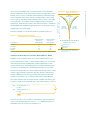
Figure 1. Solar Energy Distribution
GCHP: ground-coupled heat pump
GWHP: ground-water heat pump
GHP: geothermal heat pump
SWHP: surface-water heat pump
sun
19%
energy absorbed by
vapour, ozone, dust, etc.
8%
energy dispersed
in the atmosphere
17%
energy reflected
by clouds
4%
energy absorbed
by clouds
6%
energy reflected
by the earth’s surface
46%
energy absorbed
by the earth
What is an Earth Energy System?
An EES is a heating and cooling technology which transfers heat
from an earth or water source to provide space conditioning at greater
efficiencies than those of conventional systems. EESs can also be used
to heat domestic water.
Natural heat from the earth or water source is absorbed into a liquid,
3
Part 1
Commercial Earth Energy Systems: A Buyer’s Guide
heat transfer medium and is carried through a system of buried pipes
to a building, where in heating mode, it is upgraded to the required
temperature level via a heat pump unit. The heat is then circulated
via ductwork or through radiant heating. In cooling mode, the system
is reversed and the excess building heat is rejected back into the
cooler ground.
Like a conventional heat pump, a ground-source heat pump is essentially
an air-conditioner that can also run in reverse in the winter. However,
unlike conventional air-source heat pumps, EESs can maintain high
efficiencies and capacities even when ambient air temperatures hit
extreme values in the winter or summer because the components
of the system are not exposed to the outdoors.
Many EESs on the market have the ability to provide domestic hot water
heating through a device called a desuperheater, further increasing their
operating efficiency. Alternately, EESs may provide domestic hot water
through a dedicated water-to-water heat pump.
Significant energy savings can be achieved through the use of EESs.
Compared to conventional systems, typical reductions in energy consumption of 30 to 70 percent in the heating mode and 20 to 95 percent in
the cooling mode can be obtained.
EESs come in a wide variety of configurations that use the ground,
ground water or surface water as a heat source and sink. Examples are:
Figure 2. Basic heat
pump principle
• ground-coupled heat pumps, which use the ground as a heat source and
hot
sink either with vertical or horizontal ground heat exchangers (GHXs);
• ground-water heat pumps, which use underground (aquifer) water as
a heat source and sink; and
• surface-water heat pumps, which use surface-water bodies (lakes,
mechanical
device
ponds, etc.) as a heat source and sink.
Heat Pump Fundamentals of
Earth Energy Systems
Heat naturally flows “downhill” from higher to lower temperatures. A
heat pump is a machine that causes heat to flow in a direction opposite
to its natural tendency, or “uphill” in terms of temperature. Because
work must be done to accomplish this (i.e., going uphill), the name
heat “pump” is used to describe the device.
cold
Heating mode
4
The heat pumps that are in an EES operate following the same basic
Commercial Earth Energy Systems: A Buyer’s Guide
principles as those of most cooling and refrigerating equipment. Most
of these systems are based on two physical phenomena:
• When a liquid evaporates, it absorbs energy, and when it condenses
it releases energy.
• Any liquid will evaporate or condense at a lower temperature when
the pressure decreases and will condense or evaporate at a higher
temperature when the pressure increases.
These two principles are the basis of the mechanical vapour compression cycle, which is behind most EES heat pumps. This cycle uses the
two principles to transfer energy from a colder source to a warmer sink.
Therefore, a heat pump is nothing more than a refrigeration unit. The
only differences between a heat pump and a refrigeration unit are the
temperature levels at which they operate and the fact that heat pumps
are reversible and can provide either heating or cooling.
The Right Conditions
Commercial and institutional buildings that are best suited to EESs include the following:
• new buildings, which allow for more ready adoption of EES designs. There have also
been a number of applications where major renovations were undertaken or where
new additions to existing buildings were made that allowed EES designs to be
considered;
• buildings with large space heating and water heating energy use. Extended care
facilities, retirement communities and health care facilities are excellent candidates
for EESs;
• buildings that are located in areas where natural gas is unavailable for heating purposes;
• buildings that require simultaneous, year-round heating and cooling that can be
readily provided by a two-pipe distribution EES;
• buildings where it is important to maintain exterior aesthetics, such as heritage
building restorations; and
• buildings where space for a mechanical room is at a premium.
How Earth Energy Systems Work
Basic Operating Principle
Energy in the form of heat is present even at very low temperatures.
Provided the temperature of an object is above absolute zero (–273°C),
there is some heat energy present in the object. The temperature of the
ground is too low to heat a building directly (in Canada, the ground
temperature ranges from 4 to 10°C), but the ground still holds a vast
store of heat. A heat pump is required to upgrade this energy extracted
from the ground to a convenient level for heating, or to reject heat to
the ground effectively. This ground heat source and sink has a near
5
An EES can provide space heating and cooling and much of the hot
water requirements for most institutional/commercial buildings.
The Refrigeration Cycle: An Overview
The vast majority of heat pumps work on the principle of the vapour
compression cycle. The main components in such a heat pump system
are the compressor, the expansion valve and two heat exchangers
referred to as the evaporator and the condenser. The components are
connected to form a closed circuit, as shown in Figure 3. A fluid, known as
the working fluid or refrigerant, circulates through the four components.
In the evaporator, refrigerant enters in a cool, mostly liquid state.
The temperature of the liquid is lower than the temperature of the
heat source, such as the surrounding ground in heating mode of a
ground-coupled heat pump or the room air in cooling mode. The
warmer ground or air then causes the liquid refrigerant to evaporate,
thus absorbing heat. Refrigerant vapour from the evaporator travels to
the compressor where it is compressed to a higher pressure and temperature. Once it passes through the compressor, the refrigerant is said to
be on the “high” side of the system. The hot vapour then enters the
condenser, where it condenses and gives off heat (i.e., heating up the
building when in heating mode). Finally, the pressure of the warm liquid
refrigerant exiting the condenser is reduced through the expansion
valve. The expansion process also reduces the refrigerant temperature
before it re-enters the evaporator. The whole process can be reversed to
cool the building.
Figure 3. The Refrigeration Cycle (heating mode)
compressor
condenser
heat
low-pressure,
low-temperature
vapour
evaporator
High-pressure,
High-temperature
vapour
High-pressure,
High-temperature
liquid
Low-pressure,
Low-temperature
liquid
expansion valve
heat
Commercial Earth Energy Systems: A Buyer’s Guide
predictable performance and lower thermal and mechanical stress.
section 01
constant temperature, which is well suited to a heat pump, giving
Earth Energy System Components
The basic function of an EES is to provide heating and cooling for a
building. In addition, it may provide water heating, sometimes supplemented by a conventional water heater. To perform these functions, EESs
are made up of the following three primary sub-systems, which are
discussed more fully in Chapter 2, “Selecting an Earth Energy System.”
• an earth connection (also known as ground or ground-water loops)
Digging a trench
to lay ground loops
that extracts heat from the earth or discharges heat to the earth;
• a heat pump that transfers heat between the distribution system
and the ground or ground-water loops; and
• a distribution system to deliver the heating or cooling to the
building’s various spaces.
Why Earth Energy Systems Make Sense
An EES offers numerous benefits to building owners and tenants, many
of which lead to lower owning and operating costs.
Figure 4. Average Monthly
temperatures
in canada
Constant Ground Temperature
At a depth of eight to nine metres or more, the ground temperature is
virtually constant throughout the year, having a value close to that of
30
Degree celcius (oC)
Commercial Earth Energy Systems: A Buyer’s Guide
6
the average annual air temperature. This constant temperature environ-
25
ment is well suited to earth energy heat pumps, giving them consistent
20
performance, regardless of the outdoor temperature. In climates with
15
temperature extremes such as in Canada, this is very beneficial. Earth
10
energy can play an important role in Canada’s response to climate
5
change as both a renewable form of energy and as an energy-efficient
0
technology, resulting in low greenhouse gas (GHG) emissions.
-5
J
F
M
A
M
J
J
A
Months
Ambient Air
Earth
Groundwater
S
O
N
D
Renewable Energy
EESs are a renewable energy option. Like most renewable energy systems,
EESs make use of the sun’s energy. EESs are environmentally friendly
because approximately two-thirds of the energy they deliver comes from
renewable energy within the ground. This indirect use of solar energy
comes from the capability of the earth’s crust to store solar energy. In
fact, the earth is a massive solar energy collector that absorbs 46 percent
of the sun’s energy that radiates to earth, which amounts to more than
500 times more energy than earth’s population needs every year. EESs
can retrieve some of the energy stored in the ground to heat buildings
during the winter and, during the summer, reverse the process to reject
the building’s heat to the ground for cooling purposes. A recent climate
change analysis showed that EESs in commercial and institutional
buildings had the lowest GHG emissions of all heating, ventilating
and air-conditioning (HVAC) systems.
to be installed only when the tenant or owner occupancy is imminent.
Tenants can control comfort levels, and the thermostat control is simple
to use. The heat pumps can be located out of the occupied space (in
ceiling space above corridors, for example). This permits flexibility
in partitioning and layout of the occupied space and easily allows for
tenant space expansions. Careful planning by the owners and design
engineers will provide inherent flexibility and cost efficiency.
Space and Cost Savings
Benefits of Earth Energy Systems
in Commercial Buildings
• lowest life-cycle cost
• sometimes has a lower first cost
• lower operating and maintenance
costs
• improved comfort (individual
room control)
• small mechanical room
• aesthetic design (no roof
penetrations)
• may reduce building’s height
requirements
An EES can be all-electric, which eliminates the need for multiple
utility service entrances, fuel storage tanks, etc. The system requires
less mechanical room space than central heating and cooling systems,
meaning more space in occupied and leased areas and possibly lower
floor-to-ceiling heights. There is much less outdoor equipment, which
results in lower maintenance and security costs. With no outdoor equipment on the roof, there are less penetrations, maintenance decks and
architectural blinds and less of a need to protect equipment from
vandalism. Exterior noise is significantly reduced, and building aesthetics
are excellent. EESs also last longer, with the GHX lasting more than
30 years and the heat pumps themselves lasting typically 20 years.
Figure 5. Advantages of Choosing Earth Energy Systems
improved aesthetics,
security and reduced noise
• No exterior penetrations
• No chillers and boilers
• No outdoor condenser/
fan unit
improved comfort
• Lower air-temperature delivery
• Even temperatures
improved air quality
Operates on principle
of natural heat transfer
• No on-site combustion
products
• Less infiltration
• Lower humidity
Energy Efficiency and Environmental Benefits
Since EESs involve the transfer of natural heat and no combustive process
occurs, the only harmful environmental emissions attributable to their
use is related to the electricity required for the system’s operations, if the
source of electrical generation is from fossil fuels. EESs are also energy
efficient because for every unit of energy (electricity) required to operate
the system, the system transfers three to four times that amount of energy
(heat). Hence, the use of EESs can contribute significantly to the mitigation of GHG emissions, impacting on climate change because there are
little or no carbon dioxide emissions associated with the operation of EESs.
Earth Energy Systems
Make Environmental Sense
• low or no GHG emissions
(associated with climate change)
Part 01
A decentralized EES has built-in flexibility that allows the heat pumps
Commercial Earth Energy Systems: A Buyer’s Guide
7
Flexibility
Commercial Earth Energy Systems: A Buyer’s Guide
8
Societal Benefits
Using EESs has a positive impact on society as a whole as they use a
significant portion of renewable energy in their operation, have long
lives, and are comprised of equipment that can be recycled. The resource
is plentiful and readily available from one’s own land. The use of an EES
should always be a part of a holistic approach to building design.
Economics
Earth Energy Systems
Make Economic Sense
•
•
•
•
•
lower power requirements
secure, stable heat supply
lower resource intensity
lower maintenance, more profitability
less susceptible to energy price
fluctuations
• initial cost is not always higher than
conventional systems and may even
be lower
An EES generally costs more than a conventional HVAC system to install
but can yield substantial annual energy cost savings. Lower maintenance
costs and the displacement of fuel costs for conventional systems by
free, natural heat from a ground or water source, together with a longer
equipment life, gives EESs a lower life cycle cost than conventional options.
The initial cost of an EES is not always higher than that of a conventional
HVAC system because the costs of chillers, boilers and cooling towers,
which are part of conventional systems, are eliminated with the EES choice.
The costs associated with the earth loop and heat pump components
of an EES would have to be weighed against the equipment costs for
alternative HVAC systems.
Typical Cost of EESs
Capital Cost
The capital cost of EESs is generally higher than that of conventional
systems, but this is offset by lower operating and maintenance costs.
In addition, an EES will often reduce electrical demand for the building,
thus reducing electrical equipment and installation costs. Compared
to an all-electric heating system, the savings are even greater. The
additional cost of an EES will vary considerably depending on the site,
building type, size and alternative HVAC systems. In a sample of nine
EES-equipped commercial buildings, the average installed capital cost
of the EES was $105/m2 compared to $89/m2 for a conventional system
(about an 18 percent average cost premium for an EES). Often, as the
project gets larger, the premium for an EES becomes smaller. The
capital cost of each individual project should be carefully assessed.
Operating Cost
Offsetting the increased capital costs are the energy cost savings available
with an EES. Total building energy cost reduction can be significant and
can amount to up to 60 percent. The higher the ratio for heating and
cooling over the total building energy cost, the higher the potential for
energy cost reduction. Peak demand can be reduced by up to 35 percent.
assessed in advance. Operating cost is specific to the site and to the
system’s usage; a comprehensive analysis that includes a cost breakdown
and a sensitivity analysis should be requested from your design team.
Maintenance Cost
In addition to savings in energy costs, there is evidence indicating that
EESs can also save in maintenance costs. Where in-house labour is used,
a typical average maintenance cost is $0.95/m2 per year compared to an
average cost of $2.33/m2 per year for a water-source heat pump system.
Other savings can be factored into the maintenance cost. Your design
team should be able to provide a comprehensive analysis, upon request.
Financing Earth Energy Systems
Financing approaches to offset the higher initial cost of an EES include the following:
• a standard loan from a financing institution for the initial cost of the system,
less any down payment;
• a standard loan with a shared savings feature. This is a loan for the initial cost of the
system in which the customer pays a fixed monthly fee for a preset period. A financing
operator covers all operating and maintenance costs for the preset period;
• a lease, whereby the customer pays both equipment and maintenance costs
through lease payments while paying operating costs separately;
• end-use pricing, in which the customer pays the cost of equipment, maintenance
and operating by fixed payments over a prescribed period; and
• energy performance contracting, where a third party incurs the cost of the
equipment, maintenance and operating and is repaid through the energy savings.
These forms of financing are available from banks, financial organizations, utilities and
third-party financing.
Payback and Life-Cycle Analysis
A life-cycle analysis enables one to select from among competing
options. The investment that has the lowest total life-cycle cost (LCC)
while meeting the investor’s goal is the preferred investment. The LCC
technique sums the net cost of the EES and the competing scenarios
together with the energy and other operating costs during the useful life
of the system. The net cost includes purchase and installation, maintenance, repair, replacement and all other costs attributable to the EES.
LCC analysis gives a more meaningful economic result than a simple
payback period and integrates the concept of sustainable development.
The trade-off between capital cost and operating savings can be determined using the simple payback period. This indicator will provide an
evaluation of the time it takes to recuperate the initial investment.
Commercial Earth Energy Systems: A Buyer’s Guide
individual projects and specific locations, and these should be adequately
9
Part 01
As with capital cost differences, savings will vary considerably with
10
EESs provide an average simple payback period of about six to eight years.
Commercial Earth Energy Systems: A Buyer’s Guide
The payback periods range between immediate (in some cases where an
EES costs less than a conventional system) to just over 12 years. The
average internal rate of return for an EES is about 20 percent.
For example, studies indicate a payback period range of four to
10 years for a high-rise condominium compared to a gas boiler or
hydronic heat base case scenario. The period depends on location,
usage and base case scenario.
Natural Resources Canada’s RETScreen® software can facilitate the
LCC analysis as part of a pre-feasibility assessment. Table 1 presents the
payback periods obtained in a typical LCC analysis when comparing
an EES with a gas base case scenario.
Table 1. Payback Periods for EES (in years)
Compared with Gas Base Case*
New elementary school (3000 m2)
Seniors’ complex (7800 m2)
High-technology facility (7000 m2)
Curling rink/hockey arena (1100 m2)
Mid-size hotel (10 500 m2)
Motel (2050 m2)
Suburban office building (5200 m2)
Strip mall
Montréal
Toronto
Vancouver
13.6
7.6
–
4.8
5.9
5.4
Immediate
4.9
18.3
10.8
Immediate
Immediate
9.5
8.3
Immediate
5.4
1.3
1.8
–
–
6.1
5.7
Immediate
–
* LCC results are based on 1999 prices. As fuel prices rise, payback periods become shorter.
Table 2 presents payback periods obtained in a typical LCC analysis
when comparing an EES with an oil base case scenario.
Table 2. Payback Periods for EES (in years)
Compared with Oil Base Case*
2
New elementary school (3000 m )
Seniors’ complex (7800 m2)
High-technology facility (7000 m2)
Curling rink/hockey arena (1100 m2)
Mid-size hotel (10 500 m2)
Motel (2050 m2)
Suburban office building (5200 m2)
Strip mall
Montréal
Toronto
Vancouver
6.6
3.5
–
4.0
2.8
2.7
Immediate
2.9
8.5
4.7
Immediate
Immediate
4.2
4.0
Immediate
3.1
0.8
1.1
–
–
3.6
3.5
Immediate
–
* LCC results are based on 1999 prices. As fuel prices rise, payback periods become shorter.
The immediate payback period is a result of the EES having a lower initial
cost than the alternative HVAC system. It is important to take into
account space savings and lower HVAC system complexity, which can
often result in lower initial costs as well as maintenance savings, which
lower operational costs.
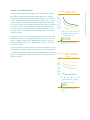
to hybrid or ground-water heat pump (GWHP) systems. Cost reductions
of 20 to 80 percent can be achieved using the latter two options under
specific conditions. GWHPs generally have a significantly lower initial
cost but are subject to more stringent regulatory and practical constraints
with regard to water use and disposal. In addition, overall efficiency
and longer-term economic advantages of GWHP systems may be less
800
750
700
650
600
550
500
450
attractive than those of GCHPs or hybrid systems due to their pump-
0
ing power demand.
The typical total cost for a GWHP system depends on the ground-water
Building system only
One 60-m well
One 120-m well
Two 60-m wells
temperature, system size and depth required for the wells, as shown in
Figure 6. GWHP systems that are smaller have a sharp cost increase.
GCHP and hybrid systems do not demonstrate as sharp a cost increase
for smaller systems.
200 400 600 800 1000 1200 1400
Diversified peak load (kW)
Source: Kavanaugh, S., A Capital Cost Comparison
of Commercial Ground-Source Heat Pump
Systems, 1994.
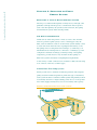
In general, when the required borehole (vertical hole) length for cooling
exceeds that for heating, a hybrid system will reduce the system’s initial
cost without a large performance penalty. The smaller the ratio of heating
shown in Figure 7.
Figure 7. Typical cost of
GCHP and Hybrid
systems
850
800
Unitary cost ($/kW)
length to cooling length, the greater the initial cost reduction will be, as
750
700
650
600
550
500
450
0
400
800
1200
1600
2000
Diversified peak load (kW)
Building system only
GCHP
Hybrid 0.3
Hybrid 0.6
Source: Kavanaugh, S., A Capital Cost Comparison
of Commercial Ground-Source Heat Pump
Systems, 1994.
Commercial Earth Energy Systems: A Buyer’s Guide
heat pumps (GCHPs) usually have the highest initial cost compared
Part 01
Studies of various types of EESs indicate that vertical ground-coupled
11
Figure 6. typical cost of
GWHP system
Unitary cost ($/kW)
Rules of Thumb on Cost
Commercial Earth Energy Systems: A Buyer’s Guide
12
Chapter 2: Selecting an Earth
Energy System
Selecting a Type of Earth Energy System
Selecting a cost-effective EES depends on many factors, although some
guidelines can help with the process. Consideration must be given to
each of the three primary sub-systems (earth connection, heat pump
and distribution system) when selecting an EES.
The Earth Connection
An EES can use either the ground or water as a heat source and heat
sink. In a ground-coupled system, a series of buried pipes carry the
fluid, often an antifreeze solution. Ground-water systems usually consist
of water wells from which the water is pumped either directly to the
heat pump’s water-to-refrigerant heat exchanger or, commonly, to an
intermediate heat exchanger that is connected to a building loop. This
configuration facilitates cleaning by reducing fouling of heat pump
components, provides heat recovery between the heat pumps on
multi-zone systems and reduces well pump-head requirements.
A wide variety of earth connections are available for EESs. The following
is an overview of the most common types.
Ground-Water Heat Pump Systems
Where ground water is available in sufficient quantities with adequate
quality and environmental regulations permit this type of installation,
such a system should be considered. GWHP systems will generally be more
economically attractive for larger buildings, since the cost of the groundwater wells (supply and injection) does not rise linearly with capacity.
Figure 8. Ground-water heat pump system
lations and insufficient water availability may limit their use in some
areas. A GWHP earth connection consists simply of water wells where
ground water from an aquifer is pumped directly from the well to the
building and, commonly, returned to the aquifer by another well. In
such cases, the supply and return wells should be spaced to avoid thermal interference. As described earlier, an intermediate heat exchanger may
be used to isolate the heat pumps from the well water. This is done to
protect the heat exchanger from the fouling, abrasive or corrosive action
of the well water. After leaving the building, the water can be pumped
back into the same aquifer via a second well, called an injection well.
Pumping power requirement is often an important factor to consider
when evaluating ground-water systems.
Vertical Ground-Coupled Heat Pump Systems
Vertical GCHP systems are well suited for most commercial buildings
and are usually the least expensive GCHP option for larger buildings.
The GHX can be located under the building footprint or parking lot,
making optimal use of available land. It has minimal environmental
impact, and the earth connection in such systems can also be used,
when properly designed, as a heat storage medium (i.e., for free cooling
and sometimes free heating).
Figure 9. vertical ground-coupled heat pump system
Commercial Earth Energy Systems: A Buyer’s Guide
been used successfully for decades. However, local environmental regu-
13
Part 01
GWHP systems were the first to appear on the market. These systems have
Commercial Earth Energy Systems: A Buyer’s Guide
14
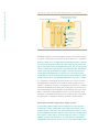
Figure 10. Vertical ground-source heat exchanger
reverse return header
(to balance pressure losses)
earth backfilled trench
supply
header
grout
(and earth backfill
when permitted)
borehole
ground
loop pipe
u-bend
This type of system is well suited for most soil conditions and when
minimum disruption of the landscaping is desired. The system consists
of a series of vertical holes (boreholes) in the ground at 45 to 150 metres
deep, into which one or two high-density polyethylene U-tubes (one downflow tube and one up-flow tube in the same well) are placed. After the
pipe is inserted, the hole is backfilled and grouted. The grouting process
consists of filling the borehole with a special material that will prevent
surface water from penetrating the aquifer or prevent the water from
one aquifer from leaking into an adjacent one. Grouting materials
usually have poorer heat-transfer characteristics than common backfill
material and cost more, but thermally enhanced grout is also available
(i.e., bentonite). Grouting the boreholes from top to bottom is often
recommended for adequate protection from water seepage from one
aquifer to another. In all cases, local regulations must also be consulted.
Following backfilling and grouting, the vertical pipes are connected to a
horizontal underground header pipe. The header pipe carries the GHX
fluid to and from the heat pumps. Vertical loops are generally more
expensive to install than horizontal ones (for small projects), but require
less piping due to the higher efficiency obtained at greater depths.
Horizontal Ground-Coupled Heat Pump Systems
A horizontal ground-coupled system configuration is often the most
economical to install, offering the lowest initial cost. However, these
systems will also often have lower seasonal efficiencies because of lower
ground temperatures and they require a larger land area. Generally, when
the system’s cooling capacity exceeds 70 kW, the surface of a typical
parking lot will not be sufficient to accommodate the GHX without
supplemental heat rejection. For these reasons, horizontal GCHP systems
loads must be properly addressed in these systems to ensure that the
ground surrounding the loop will offer a stable, long-term source and
sink for the EES.
Figure 11. Horizontal ground-coupled heat pump system
Horizontal GHXs consist of a series of pipes laid out in trenches, usually
one to two metres below the ground surface. Up to six pipes per trench
can be specified, with adequate spacing between them. Typically, about
35 to 55 metres of pipe is installed per kW of heating and cooling capacity.
Many variations of the horizontal GHX can be used. When land area is
limited, a coiled pipe – also called a “slinky” or spiral – may be used in
order to fit more piping into a trench area. Although this reduces the
amount of land used, it will require more pipe, which results in additional costs. Once the pipe is laid out, the trench is then backfilled.
About Thermal Imbalance
All the information provided in this guide assumes that the earth connection will
remain approximately at the same temperature year after year. This will be the case
for all properly designed systems. However, when a building’s cooling load differs
significantly from its heating load, the earth connection will always have either a
significant net energy gain or a significant energy loss. This is what is called “thermal
imbalance.” In the first case (energy gain), the average ground temperature may start
warming up over the years if the GHX was not properly designed (e.g., ground with
low water movement and closely packed boreholes). In the second case, the average
ground temperature will gradually fall. When designing a GHX, thermal imbalance
must always be considered in the final design to insure that long-term performances
will be maintained.
Commercial Earth Energy Systems: A Buyer’s Guide
small commercial buildings. Imbalances between the heating and cooling
15
Part 01
are usually more suited for smaller applications such as residential and
Commercial Earth Energy Systems: A Buyer’s Guide
16
Typical Land Area Required
The typical land area required for a ground-water system is usually not a critical factor.
An estimate based on a 6-m radius per well, including the presence of injection wells,
can be calculated.
The typical land area for vertical closed-loop systems can be based on an average borehole
depth of 91 m and a spacing of 5 m between the boreholes. Common land areas
required for vertical systems can vary significantly but are usually around 5 to 10 m2/kW.
Horizontal systems require the most land area. The amount of land required varies with
the GHX layout and piping arrangement required to minimize the pumping power.
Typical values for land area for horizontal systems are as follows:
Table 3. Typical Land Area required for Horizontal EES (m2/kW)
Configuration
One-pipe
Two-pipe
Four-pipe
Six-pipe
Northern Climate Regions
of North America
Southern Climate Regions
of North America
79
53
40
40
79
93
66
66
Source: Commercial/Institutional Ground-Source Heat Pump Engineering Manual. American Society of Heating,
Refrigerating and Air-Conditioning Engineers, Inc., 1995.
Direct-Expansion (DX) System
Each of the ground-coupling systems already described utilizes an
intermediate fluid to transfer heat between the ground and the
refrigerant. Use of an intermediate heat-transfer fluid necessitates a
higher compression ratio in the heat pump in order to achieve sufficient
temperature differences in the heat-transfer chain (refrigerant to fluid
to earth). Each also requires a pump to circulate water between the heat
pump and the ground loop. Direct-expansion systems remove the need
for an intermediate heat-transfer fluid, the fluid-refrigerant heat exchanger
and the circulation pump. Copper coils are installed underground for a
direct exchange of heat between refrigerant and ground. The result is
improved heat-transfer characteristics and thermodynamic performance.
However, the systems require a large amount of refrigerant and, because
the ground is subject to larger temperature extremes from the directexpansion system, there are additional design considerations. In winter
heating operation, the lower ground-coil temperature may cause the
ground moisture to freeze. Expansion of the ice buildup may cause the
ground to buckle. Also, because of the freezing potential, the ground
coil should not be located near water lines. In the summer cooling
operation, the higher coil temperatures may drive moisture from the soil.
Surface-Water System
A surface-water system is a viable and relatively low-cost EES option.
When a building is near a pond or lake, submersing a series of coiled
pipes beneath the surface will constitute the heat exchanger. This system
date this type of system. The fluid is pumped through the pipe, just as it
is in a ground-coupled system. Properly designed pond loops used in a
closed system result in negligible impacts on the aquatic ecosystem.
Piping should be buried at the shoreline to avoid damage from marine
traffic and ice.
Figure 12. Various types of horizontal GHX
A
B
Earth
Backfill
min.1.2 m
1.2 m
Ground
loop pipe
0.4 m
Sand
fill
C
D
min.0.6 m
min.1.2 m
1.2 m
0.4 m
supply
header
E
F
turnarounds
reverse
return header
coiled
pipe
(to balance
pressure losses)
G
A. Single Pipe
B. Stacked two-pipe (sand fill is
required only if rocks larger
than 5 cm across are present.)
C. Parallel two-pipe
D. Stacked parallel Four-pipe
H
E. Layout of Parallel Two-Pipe showing
Turnarounds and Header
F. Coiled pipe laid either horizontally in a
Wide Trench or vertically in a narrow trench
G. Coiled pipe laid vertically in a narrow trench
H. Coiled pipe laid horizontally in a wide trench
Commercial Earth Energy Systems: A Buyer’s Guide
be deep enough and must also have sufficient surface area to accommo-
17
Part 01
requires minimum piping and excavation, but the pond or lake must
18
Another factor to consider when selecting an EES type may be the
Commercial Earth Energy Systems: A Buyer’s Guide
availability of local contractors and installers familiar with the proposed
technology. Long-term performance as well as a number of crucial
practical considerations in designing and installing EESs can usually
be thoroughly addressed by experienced personnel.
The Heat Pump
Heat Pumps
Figure 13. Heat Pump Unit
One of the basic building blocks of any EES is the heat pump unit itself.
Heat pumps used in an EES are either water-to-air units or water-towater units, depending on the distribution system of the building. The
most common type used is the single package water-to-air heat pump,
typically ranging in size from 3.5 to 105 kW of cooling capacity. EESs
should typically use extended-range units, which allow lower entering
fluid temperatures in heating mode (liquid entering the liquid-torefrigerant heat exchanger), and higher entering fluid temperatures in
cooling mode. In these units, all the components are contained in a single
enclosure. The unit typically includes the compressor, an earth loopto-refrigerant heat exchanger, controls and a small air-distribution
system that contains the air handler, duct fan, filter, refrigerant-to-air
heat exchanger and a condensate removal system for air conditioning.
A simplified schematic of a packaged heat pump unit is illustrated below.
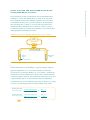
Figure 14. Simplified EES heat pump unit layout
Warm air
to building
Secondary
heat exchanger
Blower
Return
air from
building
Expansion device
Reversing
valve
Refrigerant
piping
Desuperheater
Compressor
Domestic hot
water heater
primary
heat exchanger
Ground
From Earth Connection
To Earth Connection
The desuperheater shown on the schematic provides domestic hot water
19
Part 01
Commercial Earth Energy Systems: A Buyer’s Guide
when the compressor is operating. The desuperheater is a small auxiliary
heat exchanger at the compressor outlet. It transfers excess heat from the
compressed gas to a water line that circulates water to a hot water tank.
During the cooling season, when the air conditioning runs frequently, a
desuperheater may provide all the hot water needed in certain applications.
In the last few years, the EES market has come of age, and manufacturers
now offer a wide range of products, from split systems, water-to-water
heat pumps, multi-speed compressors and dual compressors, to rooftop
versions of this equipment to suit various applications.
Typical configurations include the following:
• vertical up-flow air discharge;
• vertical counter-flow air discharge;
• horizontal ceiling-mounted;
• dual compressor units;
• split systems (compressor/water heat exchanger and air-handling
Different units are commonly used in
the industry to designate heat pumps’
heating and cooling capacities.
Generally, cooling capacity is expressed
in tons, while heating capacity is
expressed in Btu/h or kW. Converting
from one unit to another is easily
achieved using the following conversion
factors:
sections);
• large commercial vertical up-flow air-discharge units;
• two speed units, horizontal and vertical;
• floor-mounted console units;
• large commercial vertical variable air-volume units;
• 1 ton = 12 000 Btu/h
• 1 kW = 3412 Btu/h
• 1 ton = 3.517 kW
• rooftop packages;
• schoolroom ventilator units; and
• water-to-water (radiant hydronic systems).
Experienced and knowledgeable professionals should provide the proper
selection of heat pump units.
Figure 15. Horizontal heat pump unit
supply air
front
panel
return air
Tons, Btu/h and Watts
20
Commercial Earth Energy Systems: A Buyer’s Guide
Figure 16. Vertical heat pump unit
supply air
return air
front panel
EES heat pumps are available at different levels of efficiencies. Highefficiency equipment generally contains a high-efficiency compressor,
Tips on Heat Pump Sizing
and Selection
a larger air coil, a higher-efficiency fan motor and sometimes a larger
• An EES heat pump should be sized
so that, at its minimum capacity,
the equipment does not exceed
125 percent of the cooling load.
If this limit is exceeded, improper
dehumidification and operation
may result.
with a higher price tag but may be the better economic option for a
• Extended-range heat pumps should
be used.
• A minimum energy efficiency ratio
(EER) of 13, as per the Canadian
Standards Association or the AirConditioning and Refrigeration
Institute (ARI), is recommended.
• EER and COP ratings for multi-speed
or variable-speed units must be carefully interpreted. Always look at the
full-speed EER.
Care should be taken to ensure that the
controls used on the heat pumps are
easily integrated with the building
and can be serviced by regular
HVAC maintenance personnel.
refrigerant-to-water heat exchanger. High-efficiency equipment comes
given project. It is difficult to state a general rule about selecting equipment on the basis of efficiency, because the economic considerations
and merits of each system will vary depending on the application.
Table 4. Typical Cost of EES Heat Pumps
Heat Pump Efficiency Level
Standard
Medium
High
Typical Cost (per kW cooling)
$235
$270
$330
Heat Pump Sizing
Heat pumps in distributed EESs will normally be sized according to the
peak loads of each individual zone. This ensures that every room will
maintain its temperature at any given time. The diversified (block) load
should be used only to size central equipment, which can benefit from
the potential load diversity (heating loads cancelling out cooling loads)
to reduce its required size. For an EES, the earth connection should thus
be sized according to the diversified load to help minimize its size and
cost. If centralized heat pumps are used, these can also be sized using
the diversified loads. Therefore, the type of distribution system used in
a building will impact the final size of the heating and cooling equipment.
controls and piping designs are used.
GCHP and GWHP systems require the use of pumps. GCHPs need
pumps to circulate the fluid (water or antifreeze solution) throughout
the building and the earth connection. GWHPs need pumps to circulate
the fluid through the building loop, as well as separate pumps for the
ground water.
GWHP projects can sometimes become uneconomical due to excessive
pumping requirements (i.e., if the water table is too low or if the system’s
overall pressure drop is too high).
There are many options possible to optimize the pumping energy
requirements for GCHPs and GWHPs. EES designers are the primary
resource in selecting the proper pumping and piping layout that will
optimize the economic performance of an EES.
As a general rule, GCHP systems should have an installed pumping
capacity of less than 16 W per kW of peak diversified load. It is important
to consider the peak block load and not the installed heat pump capacity
when judging the adequacy of the pumping capacity. Cutting the flow to
the heat pumps that are not in operation (solenoid-valve and variablespeed pumping) is highly recommended.
GWHP pumping capacity should be judged on the merit of each project.
Optimal ground-water flow and associated pumping capacity should
always be considered in an overall system performance analysis (i.e.,
heat pump performance and the well pump). This is required because
the heat pump’s performance will generally be significantly affected by
the selected ground-water flow rate. As for GCHP systems, diversified
load – not installed capacity – should be considered in the calculations.
Evaluation of Heating and Cooling Loads
Evaluating the building’s loads is a critical step in an EES project. Given
the usually higher initial cost of an EES, over-sizing the heat pumps or
the earth connection may significantly reduce its economic attractiveness.
To determine the heating and cooling loads, the building should first be
divided into thermal zones. The zone loads are then evaluated based on
envelope thermal transmission, solar gains, internal gains (lights, people,
equipment), infiltration and ventilation.
Heating loads for the zones should be determined using the winter
design temperature for the locale. Cooling loads for the zones can be
calculated using the most recent methods of the American Society of
Heating, Refrigerating and Air-Conditioning Engineers, Inc. (ASHRAE).
These calculation methods include the effect of solar heat gain, thermal
Commercial Earth Energy Systems: A Buyer’s Guide
EES performance can be greatly penalized if inadequate pumps, pumping
21
Part 01
Pumping Concerns
22
storage in building materials and indoor/outdoor temperature differences.
Commercial Earth Energy Systems: A Buyer’s Guide
Cooling load calculations should be made for three different times during
the design day (usually July 31).
Block heating and cooling loads are needed to size the central equipment
and GHX. Block loads are the sum of the individual zone loads at the
time of the peak building load. The heating block loads should be evaluated at night conditions, and the cooling block loads evaluated at the
same three different times used for the zone load determination. The
highest of these should be selected as the design block load for cooling.
Controls
Water-Source Heat Pump
Controls for water-source heat pumps consist of low-voltage, wallmounted thermostats for each unit. These may have night set-back
capabilities. Operating fault conditions should be reset through the
thermostat rather than at the unit. Fan operation is also controlled
through the thermostat.
When an individual heat pump unit is off due to too high or low refrigerant temperature, an alarm or indicator light on the thermostat alerts
the occupants. If there is a failure of the central pump, an alarm in the
equipment room is activated, even if the standby pump is available.
Circulating Pump
A two-pump arrangement can be controlled from a time clock to automatically shut down the pumps during scheduled unoccupied periods.
The pumps run continuously in many applications. A manual switch is
normally provided to alternate pump operation in order to balance run
times and wear. A variable-speed drive can also be used for the pumps
to save energy.
Central Control/Energy Management System
Larger systems may have central control panels with individual heat-pumpunit monitoring and controls. With such a system, a night set-back can
be controlled centrally, as can morning start-up. Operation of the heat
pumps can also be controlled from a central location (scheduling) as
can the ventilation system.
The air-handling system is typical of any forced-air heating or cooling
system. A fan moves heated or cooled air through ducts to the individual
rooms and returns air to the earth energy system.
systems, including air-based, hydronic (water-based), central and
distributed systems. However, the most common system is based on
the conventional water-loop heat pump system. In this type of system,
each zone has one or more water-to-air heat pumps. All units, both in
the perimeter area and the core area, are connected to a common
hydronic system. For GCHP systems, the ground loop is normally used
directly in the heat pump’s building loop. GWHP systems will usually
isolate the building’s hydronic loop from the ground-water loop
through an intermediate plate-type heat exchanger.
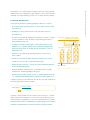
Figure 17. Typical Ground-Source Heat Pump
Distribution System
GSHP
GSHP
GSHP
GSHP
GSHP
GSHP
main
system
pump
GSHP
GSHP
GSHP
standby
system
pump
ground line
The heat pumps in a typical system, illustrated in Figure 17, are connected
in parallel with a two-pipe water loop that circulates continuously. Thus,
one heat pump can be rejecting heat to the loop while another takes
heat from the loop, allowing heat recovery between the units. Any net
heat gain or loss in the loop is transferred to the ground, lake or ground
water. The heat pumps in such distributed systems are usually packaged
units in single cabinets that include the compressor, heat exchangers,
fan, filter and controls. These cabinets may be hung above the ceiling,
installed in a closet or used as self-contained consoles on the perimeter
of the building. Common areas such as lobbies or meeting rooms can
use larger heat pumps.
A common centralized system uses a two-pipe system connected to one
or more large heat pumps, which cool or heat water that feeds the twopipe distribution system. This will typically supply fan coil units in the
various zones of the building. A two-pipe fan coil system cannot cool
and heat simultaneously, precluding heat recovery for space heating. A
central four-pipe distribution system allows simultaneous heating and
Part 01
Commercial EESs can be adapted to a wide variety of distribution
Commercial Earth Energy Systems: A Buyer’s Guide
23
The Distribution System
24
cooling. It consists of supply and return piping to both the condenser
Commercial Earth Energy Systems: A Buyer’s Guide
and the evaporator of the heat pump, which gives both chilled water
and hot water for use throughout the building. This configuration is
also readily adaptable to use the cool summer ground for free cooling
purposes. Hydronic in-floor radiant systems are another common central
system used with EESs.
A variation of the distributed system is the modular system, which has
dedicated heat pumps, water pumps and loops for specific parts of a
building. This type of system allows for independent individual control,
operation and maintenance but limits the amount of load diversity
available to size the earth connection.
As mentioned earlier, by linking all heat pumps through a common liquid
loop, the ground connection of the EES can be designed using the
diversified building load. However, for buildings where night set-back
is to be used, the morning pickup load must be considered in sizing the
ground connection because, at that time, all heat pumps are likely to
be operating in the same mode.
Fresh Air Delivery
Regardless of the distribution system, fresh air quantities should meet or
exceed local regulations, often developed following ASHRAE Standard 62,
Figure 18. Outside air mixed
at the heat pump
“Ventilation for Acceptable Indoor Air Quality.” For the common waterloop system, the fresh air is often delivered to the return air plenum. In
many buildings, ceiling space is used as the return air plenum. In such
supply
cases, fresh air is supplied to the ceiling space where individual zone heat
pumps get their supply air. In some instances, fresh air is ducted directly
to the heat pump’s fan inlet where it is mixed with return air. Another
heat
pump
outside
air
possibility is to diffuse the fresh air directly into the room. Caution is
required to ensure proper diffusion and to prevent cold drafts. Corridors
can also be used to supply outside air to adjacent rooms that have
mechanical exhaust. Regardless of the configuration selected, sufficient
ductwork for fresh air distribution must be provided to ensure that all
return
units receive adequate outside air and that short-circuiting to washroom
exhausts is avoided. In all cases, if the fresh air quantity causes an entering
air temperature to the heat pumps (after mixing with the return air)
of less than 10°C, the fresh air will have to be heated. A heat recovery
ventilator (HRV), which warms the incoming fresh air using heat
from the outgoing general exhaust air, is an energy-efficient way
of achieving this.
outside air
mixed
return
heat
pump
Supplies
Return
Grille
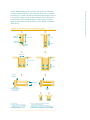
Domestic Hot Water
Water heating can be provided much more efficiently with
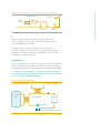
vapour-compression technology than with electrical resistance
or fossil-fuel-fired water heating.
Typically, an EES can provide domestic hot water using one of
two main configurations. It should be noted that double-wall heat
exchangers are usually required by local regulations for both of the
configurations in Figure 20 and 21.
Desuperheaters
Using a desuperheater is a common factory-installed option for EES heat
pumps. They can be easily adapted to a variety of situations, and they
are highly efficient. However, they heat water only when the heat pumps
are operating to satisfy heating or cooling space demand and therefore
need auxiliary heating. This system will seldom meet the entire domestic
hot water needs for commercial buildings.
Figure 20. Desuperheater
to earth connection
from earth connection
hot water
tank
desuperheater
indoor
coil
Compressor
(shown in cooling mode operation)
Commercial Earth Energy Systems: A Buyer’s Guide
drop-ceiling space
25
Part 01
Figure 19. Ceiling Space Used as Return Air Plenum
26
The operating principle behind a desuperheater is quite simple. Desuper-
Commercial Earth Energy Systems: A Buyer’s Guide
heaters make use of the hot refrigerant vapour leaving the compressor
to heat the water through a relatively small liquid-to-refrigerant heat
exchanger. A desuperheater can transfer 5 to 15 percent of the energy
that would otherwise be dissipated by the condenser.
The hot water generated by the desuperheater during cooling operation
is virtually free, whereas it is provided at the system’s coefficient of
performance (COP) during heating operation mode.
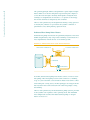
Dedicated Heat Pump Water Heaters
Dedicated heat pump water heaters are specifically designed to heat water.
Unlike desuperheaters, they can provide a building’s total domestic hot
water requirements without the use of an auxiliary system.
Figure 21. Dedicated heat pump water heater
to earth connection
from earth connection
hot water
tank
condenser
Compressor
In an EES, dedicated heat pump water heaters consist of water-to-water
heat pumps. These heat pumps use the earth connection (or building
loop) as a year-round heat source and the domestic water tank as a heat
sink. During the cooling season, the heat pump gets its energy from the
heat rejected in the earth connection from other heat pumps cooling
the building.
The hot water generated by the dedicated heat pump system is provided
at the system’s COP regardless of the operating mode. The maximum
water temperature obtained with dedicated heat pumps or desuperheaters is about 55°C.
building. Therefore, the requirements of the building will dominate the
EES design, as shown in the technical section describing earth connection sizing (see Chapter 7). The main parameters that need to be known
about a building in order to proceed with an EES design are as follows:
• the peak cooling and heating load of individual sections of the
building;
• the peak cooling and heating load of the building as a whole (also
called block load or diversified load); and
• an estimate of the annual heating and cooling energy use
(for GCHP).
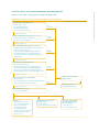
The individual sections are defined as the building’s zones, as shown in
Figure 22, Sample Building Floor Plan. Zones in a building can be
described as groups of spaces (or rooms) that have similar
• usage and function (e.g., office space vs. coffee room);
• heating and cooling systems and thermostat set-points (e.g., rooms
that have windows that face north vs. south); and/or
• periods of heating and cooling (e.g., perimeter rooms vs. interior
or core rooms).
Figure 22. Sample building floor plan
9
8
9
3
4
6
5
7
7
7
Core zone
3
4
1
2
1
Note: Numbers 1-9 represent zones.
Energy Efficiency Considerations
As with air-source heat pumps, EESs are available with widely varying
efficiency ratings. EESs intended for ground-water or open-system
applications have heating COP ratings ranging from 3.0 to 4.0 and
cooling energy efficiency ratings (EERs) between 11.0 and 17.0. Those
intended for closed-loop applications have heating COP ratings
between 2.5 and 4.0 and EERs from 10.5 to 20.0.
Diversified Loads vs. Peak Loads
At any given time, different zones
in a building will experience varying
thermal loads. Some spaces may
require cooling while others may need
heating. The total instantaneous load
of the building will often be less than
the sum of the design loads for each
space, because they do not happen
coincidentally.
Designing the ground connection
using the diversified load allows for
a reduction of the size and cost of
the EES without compromising
its efficiency.
Part 01
The primary function of an EES is to provide space conditioning to a
Commercial Earth Energy Systems Buyer’s Guide
27
Building Considerations
Commercial Earth Energy Systems: A Buyer’s Guide
28
Energy Efficiency
EES heat pump efficiencies are defined by two parameters: the coefficient of performance
(COP) and the energy efficiency ratio (EER). The steady state EER is defined as cooling output in Btu/h divided by the power input in watts. This gives the cooling load performance,
usually available at a standard rating condition. In the heating mode, the descriptor is
COP-defined as heating output divided by power input in the same units. The EER and
COP do not include central pump/tower pump and fan power input. EER is also referred
to as COPc , which means COP in cooling mode.
The minimum efficiency in each range is regulated in the same jurisdictions
as the air-source equipment. There has been a dramatic improvement in
EES efficiency over the past five years. Today, the same new developments
in compressors, motors and controls that are available to air-source heat
pump manufacturers are resulting in higher levels of efficiency for EESs.
In the lower to middle efficiency range, EESs use single-speed rotary or
reciprocating compressors, relatively standard refrigerant-to-air ratios
and oversized enhanced-surface refrigerant-to-water heat exchangers.
Mid-range efficiency units employ scroll compressors or advanced
reciprocating compressors. Units in the high-efficiency range tend to
use two-speed compressors and/or variable-speed indoor fan motors or
both, with more or less the same heat exchangers.
Figure 23. Open System earth energy System Efficiency
(at an entering water temperature of 10OC)
Reciprocating
compressor
Reciprocating
compressor and
oversized heat
exchangers
Least energy efficient
COP=3.0
EER=11.0
Advanced
reciprocating
or scroll
compressor
Variable-speed
indoor fan,
two-speed compressor
Most energy efficient
COP=4.0
EER=23.0
Figure 24. Closed-loop earth energy System Efficiency
(at an entering antifreeze water temperature of 0OC)
Reciprocating
compressor
Reciprocating
compressor and
oversized heat
exchangers
Least energy efficient
COP=2.5
EER=10.5
Advanced
reciprocating
or scroll
compressor
Variable-speed
indoor fan,
two-speed compressor
Most energy efficient
COP=4.0
EER=20.0
Design considerations are discussed more fully in Part 2 of this guide.
Typical Design Sequence
The design of a ground-source heat pump system will generally follow
this sequence:
1.
Determine local design conditions and climatic and soil thermal
characteristics.
2.
Determine building heating and cooling loads at design conditions.
3.
Select the alternative HVAC system components, including the
indoor air-distribution system type, and size the alternatives as
required. Also select equipment that will meet the demands
calculated in Step 2 (using the preliminary estimate of the entering
water temperatures to determine the heat pump’s heating and
cooling capacities and efficiencies).
4.
Determine the monthly and annual building heating and cooling
energy requirements.
5.
Make a preliminary selection of a ground-coupling system type.
6.
Determine a preliminary design of the ground-coupling system.
7.
Determine the thermal resistance of the ground-coupling system.
8.
Determine the required length of the ground-coupling system;
recalculate the entering and exiting water temperatures on the basis
of system loads and the ground-coupling system design.
9.
Redesign the ground-coupling system as required to balance the
requirements of the system load (heating and cooling) with the
effectiveness of the system. Note that designing and sizing the
system for one season (such as cooling) will impact its effectiveness
and ability to meet system load requirements during the other
season (such as heating).
10. Perform a life-cycle cost analysis on the system design (or system
design alternatives).
Evaluating the building loads adequately is the initial stage and one of
the most important steps in an EES project.
Commercial Earth Energy Systems: A Buyer’s Guide
An overview of the design requirements of EESs is provided in this chapter.
29
Part 01
Chapter 3: Designing the Earth
Connection
Commercial Earth Energy Systems: A Buyer’s Guide
30
Earth Connection Design
Regardless of the EES earth connection selected, the specifications and
size of the earth connection will depend on a number of design choices,
such as the type of distribution system (see the section on distribution
systems on pages 23–24), efficiency of the heat pumps, etc. One of the
most predominant of the choices is whether the earth connection is to
meet the heating or the cooling load. The cooling and heating loads
will usually require different capacities from the earth connection,
which may sometimes be significantly different. In these instances, it
may not be economically optimal to design for the greater of the two
capacities, and a designer must select which of the cooling or heating
loads will serve as a basis for the EES design. In all cases, the loads
attributable to the presence of pumps and domestic water heating must
be considered in the final sizing calculations for the earth connection.
When an EES earth connection is not designed to entirely meet one of
the building’s loads, auxiliary systems are required to assist the earth
connection. For example, many buildings in moderate to warm climates –
and to a lesser extent in colder climates – have cooling loads that typically
dominate heating loads. Selecting an earth connection to entirely meet
this load could lead to an excessively large system that could make the
EES uneconomical. In such a situation, the earth connection could be
sized to meet only the heating load and have a supplemental heat rejector
to compensate for the excess cooling demand (i.e., a cooling tower).
In cold climates, this situation can be reversed, and sizing the earth
connection for cooling loads can result in a smaller system but will
require the use of auxiliary heat in the winter. A better option would
be to reduce the heating load by optimizing the overall building design
(i.e., by using a heat recovery device on the exhaust air).
The choice of designing the system based on cooling or heating loads
will be closely linked to the economics of each project and should be
evaluated by the designer during the pre-feasibility analysis through
sensitivity studies.
Finally, sizing the earth connection for closed-loop systems also involves
greater uncertainty because of the uncertainty of soil conditions. A site
analysis to determine the thermal conductivity and other heat-transfer
properties of the local soil may be required. This should be the responsibility of the designing professional because it can significantly affect the
final design. A CSA standard with regard to EES design and installation
has been developed and should be consulted (CAN/CSA-C448 Series-02)
when analysing a potential project.
tower may serve to help meet the summer load. When needed, both the
earth connection and the cooling tower are operated to reject the excess
heat. Since the cooling tower is usually an open water circuit, an intermediate plate heat exchanger is often required to separate the earth
connection or building loop fluid from the water circulated in the
cooling tower.
Figure 25. Supplemental heat rejector – Cooling tower
cooling tower
outgoing
incoming
heat
exchanger
3-way valve
Furthermore, the building’s core areas often require cooling well into
the heating season. The heat pumps in these sections can then make
use of free cooling by using separate coils, called economizer coils.
When the outdoor temperature is low enough, the cooling tower can
keep the building-loop fluid cold enough to allow cooling of the core
areas using these coils, without operating the compressors. The loop
temperature could be reduced to the proper temperature if the water
bypasses the earth connection through a three-way valve. The core
zones can be cooled without using the compressors, while the perimeter
heat pumps can still operate in the heating mode. Economic viability
of this option requires a case-by-case analysis.
Another alternative to the cooling tower is the closed circuit evaporative
cooler. In this design, the heat exchanger is eliminated, and the loop water
flows directly through the cooler’s internal coil. If using the building/
earth connection directly in a cooling tower is a problem, this design
can also be achieved with a dry cooler instead.
Commercial Earth Energy Systems: A Buyer’s Guide
When the earth connection is sized for the heating requirement, a cooling
31
Part 01
Supplemental Heat Rejector: Cooling Tower
Figure 26. Cooling tower principle
air outlet
fan
fan
water
inlet
fill area
air
inlet
air
air
inlet
water
Commercial Earth Energy Systems: A Buyer’s Guide
32
These towers utilize large
fans to force air through
circulated water. The water
falls downward over fill
surfaces, which helps increase
the contact time between
the water and the air. This
helps maximize heat transfer
between the two. The transfer
of sensible and latent heat
from the water droplets to
the surrounding air allows
cooling of the water.
water outlet
A variation to the cooling tower system is the night evaporative system,
in which cooling towers are used at night to expel excess heat that
builds up in the ground loop as a result of heavy daytime use of the
EES. This prevents the temperature of the fluid in the loop from losing
its efficiency as a heat sink. Such systems may be ideal in climates
where the days are unusually hot but the nights are cool, or where
time-of-use rates are available from the local utility.
Supplemental Heat
Supplemental heat can be a viable option to reduce the size of the earth
connection for heating-dominated buildings.
In many commercial systems, a packaged water heater installed in the
building loop, much as in a closed-loop water-source heat pump system,
provides the supplemental heat. This method allows some diversity in
sizing the boiler as it lowers the installed capacity, compared to individual
unit duct heaters or room baseboard heaters. Boiler operation is controlled
to maintain a set minimum loop temperature going to the heat pumps.
An optional feature is a reset control to keep the water heater from
coming on unless the outdoor temperature falls below a certain set point.
Using supplemental heat should be avoided whenever possible,
because it reduces the overall system efficiency. Good building design
with regard to its envelope, fresh air system, etc., can allow an EES to
meet the entire heating load without relying on supplemental heating,
even in cold climates.
Figure 27. Typical steps in an earth energy system project
(major players in each step are given in italics)
Preliminary considerations
(architect, engineer, owner)
not
attractive
• is heating load significant?
• is air-conditioning required?
• is electricity competitively priced?
Proceed to next step
Other considerations (architect, engineer, owner)
Site not
suitable
• is mechanical room space at a premium?
• are exterior aesthetics important?
Proceed to next step
Site considerations (hydrogeologist, engineer)
• is sufficient surface water available for a lake loop system?
(>3000 sq. ft./ton, >6 ft. deep)
• are the groundwater quality and quantity adequate?
• is the capacity suitable for a horizontal ground heat
exchanger (20-30 tons)? vertical ground heat exchanger
(100-200 tons)?
Site not
suitable
Proceed to next step
Detailed site considerations
(hydrogeologist, driller, engineer)
• do a detailed site survey to assess remaining options
• determine the availability of drillers/drilling equipment
• assess the costs of the different ground-source options
• do a pre-feasibility analysis (i.e., by using the RETScreen® tool)
Site not
suitable
Proceed to next step
Select an alternative
HVAC system
Detailed feasibility assessment
(engineer, architect)
• do a detailed performance comparison with HVAC alternatives
• also do a detailed LCC economic comparison
not
acceptable
Detailed design of
alternatives system
Proceed to next step
Detailed design (engineer)
• select a system by attributes
Central:
• unloading capacity needed
• have a lower installed tonnage
(due to a diversified load)
• need less pumping than
decentralized water-loop
• are less reliable than decentralized
(unit failure has greater effect)
• have no recovery
Decentralized two-pipe
water loops:
• are more reliable
• require less ground heat exchanger
Individual heat pumps
with separate ground
heat exchanger:
• require more loops
• need less pumping energy
Part 01
Figure 27 is an outline of the typical steps when installing an EES.
Commercial Earth Energy Systems: A Buyer’s Guide
33
Typical Steps in an Earth Energy System Project
Commercial Earth Energy Systems: A Buyer’s Guide
34
Chapter 4: Important Considerations
Environmental Factors
Ground-Loop Fluids
Antifreeze solutions are required in closed-loop EESs in colder climates
to prevent freezing during heating operation. It is important to be aware
of the potential impacts and risks of the available antifreeze alternatives,
given that some antifreeze agents are toxic, corrosive or flammable.
Ethanol is an efficient thermal fluid with low toxicity and is biodegradable.
Ground loop or “slinky”
Propylene glycol is non-toxic, non-corrosive and non-flammable but is
less efficient as a thermal fluid. From an environmental standpoint (and
for low risk of health, fire and corrosion) propylene glycol is an attractive
antifreeze. Potassium acetate and methanol have the highest water and
underground pollution impact. Methanol, although a very efficient
thermal fluid, is highly toxic and non-biodegradable. Its use is limited
in many areas; check with local authorities. Potassium acetate, although
efficient and biodegradable, is prone to leakage problems and corrosion
in systems that have threaded joints.
Therefore, caution must be exercised when using methanol (fire, health
and environmental risks) and potassium acetate (leakage and environmental risks). The heat pump supplier should approve the choice of
antifreeze solution.
EES designers and engineers should always evaluate the risk and
impact of the selected ground-loop fluid.
Effect of Ground Temperature on the Environment
There is little or no documented evidence of negative impacts on
organisms or plants resulting from the lower (and higher) ground
temperatures associated with the operation of EESs.
Open-water or well-water systems are limited in use for large scale
commercial and industrial installations, due to the need for a sustainable
yield of high-quality ground water equal to just over three litres per
minutes for each kW of rated heat pump system output. EES water
discharge must return to the source aquifer to avoid depletion and/or
contamination of other water-bearing zones.
Ground-water and surface-water extraction and usage are subject to the
provisions of provincial and territorial acts and regulations intended to
protect water resources. In accordance with CAN/CSA-C448 Series-02,
due consideration should be given to:
• easements or rights of access to equipment by persons or agencies;
• quality and chemical composition of ground water;
• evidence of peak sustainable yield (including for other domestic
35
Part 01
Commercial Earth Energy Systems: A Buyer’s Guide
services); and
• location and sustainable capacity of discharge wells.
Refrigerants: Ozone Layer and Regulation
As described in the overview of the refrigeration cycle (see page 5),
EES heat pumps usually require the use of a refrigerant. Traditionally, the
most common working fluid for heat pumps has been HCFC-22 (R-22).
However, HCFC-22 contains chlorine, and even though it has much lower
ozone-depletion potential (ODP) than chlorofluorocarbons (CFCs) –
typically 2 to 5 percent of CFC-12 – its production and use will be
prohibited. This is the reason why hydrochlorofluorocarbons (HCFCs)
are sometimes called transitional refrigerants. The phase-out schedule
of HCFCs for industrialized countries, which was agreed to under the
Montréal Protocol and its amendments, is shown in Table 5. HCFC-22
should be phased out for industrialized countries by the year 2010 and
should be phased out entirely by 2020.
Table 5. Phase-Out Schedule for HCFCs
Date
Control Measure
1 January 1996
• CFCs phased out
• HCFCs frozen at 1989 levels of HCFC + 2.8 percent of
1989 consumption of CFCs (base level)
• HCFCs reduced by 35 percent below base levels
• HCFCs reduced by 65 percent
• HCFCs reduced by 90 percent
• HCFCs phased out, allowing for a service tail of up to
0.5 percent until 2030 for existing refrigeration and
air-conditioning equipment
1
1
1
1
January
January
January
January
2004
2010
2015
2020
Most EES heat pumps currently being marketed still use HCFC-22 as the
refrigerant, although units using R-404a and R-410a are available.
HCFC-22 Alternatives
Research and development are underway to develop substitutes for
HCFC-22 since it is the predominant refrigerant used in heat pumps
and air conditioners.
The long-term substitutes will probably be blends of various
hydrofluorocarbon (HFC) refrigerants since they have little or
no ozone-depletion potential.
Lubricants
Special attention must be given to the
use of lubricants with new refrigerants.
Mineral oils are non-miscible with
these refrigerants. Normally only esterbased lubricant oils recommended by
the refrigerant manufacturer should
be used. Mineral oil residues must
HFCs
HFCs can be considered long-term alternative refrigerants. This means
that they are chlorine-free refrigerants, such as HFC-134a, HFC-32 and
HFC-125. Since they do not contribute to ozone depletion, these are
the major components of alternatives to HCFC-22.
be completely removed during
retrofitting.
36
However, they do contribute to climate change. Direct use of HFCs in
Commercial Earth Energy Systems: A Buyer’s Guide
ground-source heat pump systems is not possible, so refrigerant manufacturer devise “mixtures” of HFC to mimic HCFC-22 characteristics.
For instance, R-410A is a blend of HFC-32 and HFC-125. Another example
is R-407C, a blend of HFC-134a, HFC-32 and HFC-125. They are mixed
in such a way that they behave closely like HCFC-22 and possess similar
thermodynamic properties.
Legislation
Federal legislation applying to EESs is limited to mechanical safety
requirements and performance certification under the Energy Efficiency
Act, except
• when installed in buildings owned by the Government of Canada
(Public Works and Government Services Canada);
• lake loops in navigable waterways or fishery habitats (Transport
Canada); and
• installations in national parks or Indian reserves (Indian and
Northern Affairs Canada).
Application of Provincial/Territorial Building Codes
Regional limitations are intended to protect special interests. One must
also ensure compliance with national standards. Municipal authorities
are required to implement the provincial or territorial regulations where
the responsibility is assumed by a third party, such as a conservation
authority, and to ensure compliance with the proper provincial or
territorial building code.
National Standards
Like requirements for other HVAC systems, all EESs are subject to
national standards for performance certification and installation. The
following standards are referenced in most technical and regulatory publications, with full recognition by industry, engineers and regulators.
• CAN/CSA-C448 Series-02 – a design and installation standard for
earth energy systems, comprised of three parts:
1) C448.1-02 – Design and Installation of Earth Energy Systems for
Commercial and Institutional Buildings, which contains requirements
applicable to any system within the scope of this standard.
2) C448.2-02 – Design and Installation of Earth Energy Systems for
Residential and Other Small Buildings, which has alternative
requirements for houses and small buildings.
.
The CAN/CSA-C448 series supercedes standard CAN/CSA-C445-M92
(R1998) (Design and Installation of Earth Energy Heat Pump Systems for
Residential and Other Small Buildings) and CAN/CSA-C447-94 (R1999)
(Design and Installation of Earth Energy Heat Pump Systems for Commercial
and Institutional Buildings). Installation and maintenance manuals are
provided to support these standards with approved industry practice.
• CAN/CSA-C748-94 (R1999) – a standard for the performance of directexpansion ground-source heat pumps.
• CAN/CSA-C13256-01 – a performance rating standard for earth energy
heat pumps providing COP (heating) and EER (cooling) data, as
required by the Energy Efficiency Act of Canada. Certified performance
data for each eligible make and model is clearly visible on every unit
offered for sale in Canada. Standard CAN/CSA-C13256 is comprised
of two parts:
• Part 1 (CAN/CSA-C13256-1-01): Water-to-air and brine-to-air heat
pumps; and
• Part 2 (CAN/CSA-C13256-2-01): Water-to-water and brine-to-water
heat pumps.
Parts 1 and 2 together supersede CAN/CSA-C446-94 (Performance
of Ground Source Heat Pumps) and CAN/CSA-C655-M91 (Performance
Standard for Internal Water-Loop Heat Pumps).
Planning, Installation and Security
Unlike most other heating and cooling systems, the installation of an
EES requires significant exterior civil works. This will require a geotechnical evaluation of the site and a careful definition of existing services
to avoid accidental damage or personal injury. A detailed plan and
specification referencing CAN/CSA-C448.1-02 (see above reference to
national standards) must be submitted to the local inspection
authority for prior approval.
In many jurisdictions, the replacement of a heating and cooling system
using the same source of energy does not normally require a formal
application under the National Building Code of Canada. All earth energy
retrofits and first-time installations, however, require a formal application
due to provincial and territorial regulations and the need for exterior
civil works. Work should not proceed until formal approval has been
received with a schedule of proposed inspections. The use of heavy
equipment such as drill rigs, excavators and other civil work machinery
will require a hard-hat zone to comply with provincial and territorial
occupational safety regulations and general work safety practices. It would
be prudent to rope off the affected land area with appropriate notices and
Commercial Earth Energy Systems: A Buyer’s Guide
Storage Systems for Commercial and Institutional Buildings, which
applies to the intentional storage of energy in the earth for later use.
37
Part 01
3) C448.3-02 – Design and Installation of Underground Thermal Energy
38
maintain a 24-hour security guard until all operations cease and the
Commercial Earth Energy Systems: A Buyer’s Guide
original ground profile is reinstated. The installation or retrofit of all
internal systems must be conducted with diligence to ensure maximum
performance according to design. Extra precautions should be taken to
avoid injury and protect health while recharging the refrigerant or
antifreeze solution to the ground loop.
Warranty and Life Expectancy
Look for a warranty that clearly states the terms involved and the
responsibilities of the players. Equipment warranties can be invalidated
by lack of routine maintenance such as filter changes, and these conditions should be clearly understood from the outset. Typical warranty
periods for heat pump units are one year (for the entire unit) and five
years for the compressor. For warranties on installation quality and
other equipment, consult with your general contractor.
Water-source heat pumps have a life expectancy of 20 years; ground
loops have a life expectancy of more than 30 years.
Maintenance
Like other commercial heating and cooling systems, there are maintenance tasks to be performed periodically. These include the following:
• changing air filters;
• lubricating motors;
• changing fan belts;
• checking antifreeze concentration and inhibitors;
• cleaning open-loop heat exchangers (where applicable);
• cleaning grilles/registers;
• cleaning ducts; and
• checking air vents.
Cooling tower maintenance (which can be extensive) is eliminated,
unless the system is a hybrid.
Little Known Facts About the Maintenance of EES Systems
The reliability of EESs is evident in a recent study of service and maintenance on
38 commercial installations, where a total of 723 corrective actions were taken for
2238 heat pumps. This represents only six corrective actions per 100 unit years of
operation. The average age of the buildings was 5.6 years. The most frequent corrective
action was compressor repair or replacement, representing 29 percent of all corrective
actions. This translates into replacing only 1.7 percent of the compressors per year,
compared to 3.3 percent for conventional water-loop systems.
Part 2
Advanced Topics and Technical Details
Part 2 of this guide elaborates upon the technical
and economic aspects governing the design, sizing
and installation of an EES.
Commercial Earth Energy Systems: A Buyer’s Guide
40
Chapter 5: Understanding Heat Pump
Performance and Efficiency
About Heat Sources, Sinks and Heat Pump Lift
One of the most important characteristics of heat pumps is that the
efficiency of the unit and the energy required to operate it are directly
related to the temperatures between which it operates. In heat pump
terminology, the difference between the temperatures where the heat is
extracted – the “source” – and the temperature where the heat is delivered –
the “sink” – is called the “lift.” The smaller the lift, the higher the
efficiency will be. This is important because it forms the basis for the
efficiency advantage of the EES heat pumps over air-source heat pumps.
An air-source heat pump, or air-source air conditioner for that matter, must
remove heat from cold outside air in the winter and reject heat to hot
outside air in the summer. In contrast, the EES heat pumps extract heat
from relatively warm ground (or ground water) in the winter and reject
heat to the same relatively cool ground (or ground water) in the summer.
Figure 28. Air-source heat pump lift vs. EES lift
temperature
to sink:
+20ºC
air-source heat pump
lift
temperature
from outside
air source:
-20ºC
earth Energy Systems (EES)
temperature
to sink:
+20ºC
temperature
from ground or
ground water
source:
+10ºC
lift
lower lift = higher efficiency
(Due to lower energy consumption)
As a result, EESs, regardless of the season, are always “lifting” the heat
over a shorter temperature differential than the air-source heat pump.
This leads to higher efficiency and lower energy use. Also, less energy is
required to move a liquid (in an EES) than to move air (in an air-source
heat pump system).
Typical Heat Sources and Sinks
As previously mentioned, the performance of a heat pump is closely
related to the characteristics of the heat source and sink. Ideally, the
heat source should be as warm and stable as possible during the heating
season and the heat sink as cool as possible during the cooling season.
For a heat pump, the typical sources and sinks available translate into
41
Commercial Earth Energy Systems: A Buyer’s Guide
Part 2
typical pressure differentials between which the compressor will have to
work. The higher the pressure differential, the greater the required work
per unit mass of refrigerant.
Table 6. Typical Minimum Temperature Levels
for Common Heat Sources in Heating Mode
Heat Source
Typical Minimum Temperature (°C)
Ambient air
Ground water
Surface water
Ground
-30°C to -15°C
4°C to 10°C
0°C to 10°C
4°C to 10°C
A heat pump that uses air as its source and sink is often called an air-toair heat pump or air-source heat pump (ASHP). EES heat pumps, which
use water or an antifreeze solution as its cooling sink, are generally
referred to as water-to-air or water-source heat pumps.
Defining Heat Pump Efficiency
Heat pump efficiency is defined as the useful energy delivered, divided
by the energy supplied to perform that function. The heating energy
delivered by a heat pump is the sum of the heat extracted from the heat
source and the energy needed to drive the cycle (i.e., compressor motor
energy). The cooling effect delivered by a heat pump includes only the
energy extracted from the source.
The coefficient of performance (COP) is used to define the heating
performance of heat pumps. COP is defined as the ratio of heat delivered
Example – Using the COP
by the heat pump and the electricity supplied to the heat pump to
If equipment heating capacity
and COP are known, the equipment
power input can be estimated. For
example, if the equipment has a
heating capacity of 20 kW at a COP
of 3.0, the power input would be:
deliver the useful heat. Therefore, the overall COP should include an
allowance for pumping and fan energy, as indicated in the following
equation:
COP heating =
20 kW/(3.0 COP) = 6.7 kW
Useful Heating Energy
Compressor and Fan and Pump Energy
COP can also be used to define a heat pump’s cooling efficiency. In this
case, the only difference is that the compressor and fan energy are not
present in the useful cooling energy term. However, it is common in the
industry to express the cooling efficiency in terms of its energy efficiency
ratio (EER). The EER is equivalent to the COP with the exception that
the heat from the source is expressed in Btu/h instead of W or kW.
COPcooling =
Useful Cooling Energy*
Compressor and Fan and Pump Energy
* Useful cooling energy = heat removed from room.
EER vs. COP
EER = COP X 3.413
Both the COP and EER values for EES heat pumps are single-point values
only: i.e., they are valid only at the specific test conditions used in the
Example – Using the EER
rating. These conditions are usually more advantageous than those met
If equipment cooling capacity and
EER are known, the power can be
estimated. For example, if the equipment has a total cooling capacity
of 60 MBtu/h* at an EER of 12,
the power input would be
in the field. In addition, COPs and EERs are usually reported without
consideration for pump energy. These values are useful mainly for
comparing equipment.
The COP or EER of a heat pump is closely related to the temperature lift
60 000 Btu/h / (12 Btu/h/W X 1000 W/kW) = 5 kW
of the heat pump. The greater the lift, the lower the efficiency.
* MBtu/h = 1000 Btu/h
Factors Affecting Heat Pump Performance
A heat pump EER and COP depend on many factors, such as the temperature of the entering liquid, water flow rate through the unit, airflow
rate and the temperature of the entering air. In general, the main factors
affecting the performance of heat pumps include the following:
• the temperatures of the heat source and heat distribution system;
Figure 29. Lift Effect on
heat pump
performance
• the auxiliary energy consumption (pumps, fans, supplementary heat
for hybrid system, etc.);
16
Coefficient of
performance (COP)
Commercial Earth Energy Systems: A Buyer’s Guide
42
• the efficiency level of the heat pump;
14
12
• the sizing of the heat pump in relation to the heat demand and the
10
operating characteristics of the heat pump; and
8
• the heat pump control system.
6
4
Rating Heat Pumps
2
0
0
20
30
40
50
Lift (ºC)
Theoretical limit
EES systems
High efficiency ASHP
Standard ASHP
60
Different types of heat pumps are tested and rated according to different
standards. This is a potentially confusing aspect of EES heat pump rating.
Rated heating and cooling performance values should be used only for
comparing units of the same type (i.e., ASHP to ASHP or GSHP to
GSHP). The ratings used for different types of equipment (i.e., ASHP,
GSHP) are not generally comparable.
In Canada, the Canadian Standards Association (CSA) has published
Standard CAN/CSA-C13256 upon which EES heat pumps are to be rated.
In the United States, the American Refrigerant Institute (ARI) rates EES
heat pumps using two different standards. Equipment rated as per CSA
standards is listed in the CSA’s Energy Efficiency Directory. ARI results
are published every six months in the Directory of Certified Applied Airconditioning Products (for GSHPs) and the Directory of Certified Unitary
Products (for ASHPs).
43
GCHP
GWHP
WLHP1
ASHP2
1
Water-loop heat pump
2
Unitary ASHP of less than 19 kW capacity
CSA
ARI
C13256
C13256
C13256
C273.31
330
325
320
210/2402
Part 01
Type
Commercial Earth Energy Systems: A Buyer’s Guide
Table 7. Applicable Standards for Different Types
of Heat Pumps
Rating conditions for the GSHP equipment are shown in the
following table:
Table 8. Rating Conditions for EES Heat Pump Equipment
Type
Standard
EFT1
Cooling
(°C)
GCHP
GWHP
C13256
C13256
25
10
1
EFT
Heating
(°C)
Standard
(°C)
EFT
Cooling
(°C)
EFT
Heating
(°C)
10
10
ARI
ARI
25
21
10
10
Entering fluid temperature
Published ratings incorporate the effect of fans. GWHP ratings also
include a pump penalty, given the greater pumping head that GWHPs
usually have.
In Canada, federal regulations authorized by the Energy Efficiency Act
apply to GCHPs and GWHPs. The regulations set the minimum efficiency
that these products must meet to be imported into or manufactured
in Canada. The reported efficiencies have to be established according
to the appropriate CSA standard. The current minimum efficiency
requirements for EES heat pumps are found in Table 9.
Table 9. Minimum Efficiency Requirements for
EES Heat Pumps
Type
Standard
Cooling EER
Heating COP
GCHP
GWHP
WLHP
C13256
C13256
C13256
10.5
11.0
10.0
2.5
3.0
3.9
ASHP Ratings
The major difference between ratings
for ASHPs and EESs is that the airsource values are seasonal. They are
intended to reflect the total heating
or cooling output for the season,
divided by the total electrical input
for the season. It takes into account
the variable heating and/or cooling
demands, the variable heat source
and sink temperatures over the year,
and includes the energy demand
for defrosting.
44
Commercial Earth Energy Systems: A Buyer’s Guide
Chapter 6: Evaluating Heating, Cooling
Loads and Energy Use
Evaluating Building Loads
The design of any commercial building HVAC system requires a licensed
professional engineer and must be done according to all other aspects of
the building as a system. An EES is no exception.
One of the most frequent problems encountered with EES is improper
sizing of the heat pumps or the earth connection. Rigorous building
load calculation procedures should be used in the EES-sizing process;
rules of thumb should never serve for sizing purposes. ASHRAE has
established one of the most widely known and accepted standards for
the determination of design heating and cooling loads. CSA standard
CAN/CSA-C448.1-02 recommends using the ASHRAE heating and
cooling load methods (ASHRAE Handbook Fundamentals, 2001).
Evaluating commercial building loads is complex and usually time
consuming. A number of software programs are available to help designers
proceed with this evaluation. However, preliminary design for simple
buildings can still be evaluated using hand calculations or rudimentary
spreadsheet programs. In all cases, one must be aware that evaluating the
building load is one of the most important steps in designing an EES.
Also, since an EES can benefit from a building’s diversified load, this load
needs to be evaluated in addition to calculating the individual zone’s
heating and cooling load for heat pump design purposes.
Heating and Cooling Load Calculation
The first step in the sizing process usually involves calculating each
zone’s peak heating and cooling load as well as the whole-building peak
loads. The following factors typically need to be considered when
performing these calculations:
Latent Loads
Latent load is the term used to define
the energy attributable to humidity
injection in a space. Removing 1 kg
of humidity requires 0.7 kWh of energy.
This load comes into play only under
cooling conditions, when the heat
pumps are actually removing some
of that humidity.
• Solar gains through windows: Standard double-glazed windows can
let up to 75 percent of this energy penetrate the building, where it
becomes a cooling load. Additional window treatments such as tinted
and reflective glazing, shading and draperies can further reduce
solar gains.
• Internal gains from occupants (including latent heat for cooling
purposes): Each adult will typically generate about 75 W of sensible
energy and 55 W of latent energy.
2
about 20 W/m in office buildings but can be as high as 40 to 50 W/m .
The equipment load (also called plug-load) is often in the 2- to 5-W/m2
range but can be as high as 15 to 20 W/m2.
• Outside air loads (sensible and latent) from ventilation and infiltration:
All buildings should meet at least the minimum outside air requirements imposed in their local jurisdiction. The amount of outside air
is often taken from ASHRAE Standard 62. A typical value for outside
airflow rate is 15 L/s/occupant.
• Heat gains or losses through windows, walls, floors and roofs: These
gains are mostly important for heating load calculation but may still
have some impact for the cooling load, especially the windows, and
heat gain. The amount of heat transfer through these components
can be estimated using the following formula:
Heat gain/loss = Area X (surface temperature outside – surface temperature inside)/RSI value.
For typical RSI values, or effective thermal resistance in the
International System of Units (SI), see Table 10.
Table 10. Typical RSI Values
Insulation Level
Low
Medium
High
Wall RSI-Value
(m2·°C)/W*
Roof RSI-Value
(m2·°C)/W
Window
RSI-value
(m2·°C)/W
1.5
3.0
5.0
2.0
4.0
7.0
0.2
0.3
0.5
* (m2·°C)/W denotes square metre by degree Celcius, per watt.
Using the very simplified values and formulas presented here can help
in getting a rough estimate of a zone heating and cooling load. Some
other important points to know about load calculations are as follows:
• The heating load calculation must be done without credit for
occupants and internal gains, since this load usually occurs at night.
• Zone loads are calculated with consideration only to the zone’s peak
gains (i.e., solar) or losses (for heating).
• Each zone’s peak loads may occur at different moments. However,
for hand calculations, cooling loads are usually calculated during the
hottest day of the summer for three different times for each zone. The
greatest of the calculated loads are selected as the zone peak loads.
• Heating loads need only to be evaluated at the heating design temperature, since no credit for solar gain or internal gain is considered.
However, since some areas in the core of a building may require
cooling at all times, these zones may need to consider internal gain
even under winter design conditions.
45
Commercial Earth Energy Systems: A Buyer’s Guide
2
Part 01
• Internal gains from lighting and equipment: Lighting power is often
Commercial Earth Energy Systems: A Buyer’s Guide
46
• Whole-building loads are calculated considering all zones’ loads. The
whole-building peak loads may not occur at the same moment as that
of any of its zones. Precise determination of the time of occurrence of
the whole-building load requires either extensive hand calculations
or, more realistically, an hourly computer simulation. Approximate
cooling block load can be estimated using the greatest of the sum of
all zone loads for the three time periods previously considered.
• Design temperatures must be obtained from a reliable source, such as
ASHRAE Handbook Fundamentals, 2001.
Typical values for building heating load range from 20 to 120 W/m2.
Cooling loads generally vary from 50 W/m2 for buildings in cool
climates with little internal gains to 200 W/m2 or more for commercial
buildings in hot climates with high internal gains.
For a thorough calculation of the zones and whole-building loads,
one of the following three methods presented in ASHRAE should
be employed:
• Transfer Function Method (TFM): This is the most complex of the
methods proposed by ASHRAE and requires the use of a computer
program or advanced spreadsheet.
• Cooling Load Temperature Differential/Cooling Load Factors
(CLTD/CLF): This method is derived from the TFM method and uses
tabulated data to simplify the calculation process. The method can be
fairly easily transferred into simple spreadsheet programs but has
some limitations due to the use of tabulated data.
• Total Equivalent Temperature Differential/Time-Averaging (TETD/TA):
This was the preferred method for hand or simple spreadsheet calculation before the introduction of the CLTD/CLF method.
These three methods are well documented in ASHRAE Handbook
Fundamentals, 2001. When designing an EES, the method used for
obtaining the zones and whole-building loads should always be
documented to ensure its adequacy.
rejected in the cooling mode compared to that in the heating mode. If a
large imbalance exists in these annual values, it can reduce GHX performance, and its design should take this into consideration. To evaluate
the energy extracted and rejected to the ground, an annual energy-use
calculation is required. For a commercial building, this type of calculation
can rarely, if ever, be performed manually to obtain a reliable estimate.
There are a few simplified methods that are still used today to obtain
ballpark figures, but these should be treated with caution given their
extremely simplistic approach to commercial building energy use.
Energy calculations can be done using one of three basic methods:
• Degree-day method: This simple procedure requires knowing only two
parameters to estimate the annual energy use. Its value is extremely
limited for commercial buildings. Crude estimates may be derived
from it, but these can hardly serve in any estimating procedures,
even at an early stage. Its use is limited to the residential sector.
• Bin method: Bin methods represent the best way to obtain early
estimates for annual energy consumption. The method accounts for
the changing outdoor temperature and partial load conditions. It can
be automated easily in a spreadsheet program and can be used to treat
multiple-zone buildings. Hand calculations of simple, residential-type
buildings are feasible. Commercial buildings would be more difficult
to treat using hand calculations.
• Hour-by-hour method: This is one of the most advanced methods for
performing annual energy use calculations. It is arguably the best, but
most complex method to select. Many commercial programs are
available for performing hourly simulation, one of the better known
being DOE2 and its derivatives. Care must be taken when performing
a detailed hourly simulation. Easy to use software interfaces must not
preclude a thorough validation of the input data and verification of
the outputs. Validity of the results, even with the best hourly simulation model, will depend to a greater extent on its adequate use rather
than on its various capabilities.
The “Energy Estimating Methods” chapter of ASHRAE Handbook
Fundamentals, 2001 describes in detail these methods and includes
examples.
Typical commercial buildings in Canada will use between
100 and 400 kWh/m2/year (kilowatt-hours per square metre, per year).
Commercial Earth Energy Systems: A Buyer’s Guide
Long-term EES performance can be influenced by the amount of energy
47
Part 01
Energy-Use Calculation
Commercial Earth Energy Systems: A Buyer’s Guide
48
Chapter 7: Sizing Heat Pumps and
Ground Heat Exchangers
Sizing the Heat Pumps
Once the cooling and heating loads are known, a decision must be made
with regard to equipment selection. Should the equipment size be based
Humidity Considerations
on the heating load or the cooling load?
EES heat pumps are usually designed
to operate with a sensible heat ratio
(SHR) typically of 0.75. The SHR is
defined as the ratio of the sensible
cooling capacity over the total capacity.
A common heat pump design guideline is that the cooling capacity
An SHR of about 0.75 is sufficient to
maintain adequate humidity levels
(i.e., meeting the latent load) in most
Canadian locations.
fans may help circumvent this limit. The heat pump should be sized
In general, when estimating the cooling loads one should verify the zone’s
SHR. This value should be equal or
superior to the heat pump’s SHR.
should not exceed 125 percent of the peak sensible cooling load.
Otherwise, dehumidification may not be adequate, and occupant comfort
may be compromised. Using multiple compressor units or variable-speed
based on a sensible cooling capacity within 10 percent of the sensible
space load. In cases where heating loads largely dominate the cooling
loads, preconditioning the outside air may help balance out the loads.
In such cases, the earth connection must be sized according to the loads
actually met by the heat pumps and not the total loads. By reducing the
gap between heating and cooling loads, preconditioning the outside air
may also help reduce the need for hybrid systems. As in other industries,
knowledge and methods evolve over time. Other methods and principles
are used and provide adequate results. The buyer should refer to a
trained designer for further information.
Outside Air Preconditioning
If the temperature going into the heat pumps, after mixing with the
outside air, can go below 10°C, preheating the outside air is required.
HRVs in Cold Climates
Also, as mentioned above, outside air preheating may be desired to
In cold climates, HRVs may require
supplemental heating, usually electric,
to ensure that on the coldest days the
incoming mixed air does not fall
below 10°C. Also, in cold climates,
a defrost mechanism on HRVs is
usually required.
avoid large imbalances between design heating and cooling loads. There
are several ways for preconditioning outside air. The most common
options are as follows:
• Heat recovery ventilator (HRV) or total recovery ventilator (TRV): The
HRV is an energy-efficient method for preheating outdoor air. The
HRV extracts some of the heat in the exhaust air to precondition the
outside air. A TRV will not only exchange heat between the exhaust
and fresh air stream, but also exchange humidity. In humid climates,
this will reduce the latent load on the heat pumps. In cold climates,
it will reduce humidification needs.
• Water-to-water heat pumps: Another option that integrates itself
naturally in an EES is the use of a water-to-water heat pump to precondition the outside air. This system uses a dedicated water-to-water
heat pump that can heat and cool the outside air. Therefore, this system
may also help reduce the latent load under cooling conditions.
efficient than the previous two but may turn out to be part of an
overall optimal economic design.
• Other types of recovery systems: There are many more heat recovery
systems that may play the same role as an HRV. Heat pipe systems, air-toair heat pumps between the air stream and others may also be used.
Sizing Ground Heat Exchangers (GHXs)
The design of a GHX is in a few ways similar to that of a conventional
heat exchanger. The load on the heat exchanger will drive the sizing
process. For GHXs under specific soil conditions, the building load
(cooling or heating) is the primary factor that influences its size.
However, as for its conventional counterpart, the final size of the GHX
is determined by design choices. When designing a conventional heat
exchanger, both the inlet and outlet temperatures and flow rates are
usually provided to determine its size. The final size will depend on the
designer’s requirement with regard to the temperature of the fluids coming
out of the heat exchanger. This also applies for a GHX. The final size of
the GHX will be determined by the designer’s requirements for the
minimum or maximum temperatures allowed at the GHX’s outlet
during the course of the year.
However, the maximum and minimum GHX outlet temperatures have
a limited range of acceptable values. Practical constraints, mainly from
the heat pumps, tend to make this design decision more straightforward.
For example, extended-range heat pumps will usually have a recommended
minimum entering fluid temperature (EFT) of –6°C , and a recommended
maximum EFT of 43°C , with values in the 27 to 32°C range primarily
being used. Specific designs may go below and above these temperatures
but would not be common.
A designer can vary these values to optimize first cost against performance.
Typically, the higher the value for the minimum temperature allowed at
the GHX outlet, the higher the system’s annual performance. However,
the resulting GHX will be longer, and the initial cost will be higher.
This applies to lower values for the maximum GHX outlet temperature.
Commercial Earth Energy Systems: A Buyer’s Guide
electric heaters, hot water or steam. These options are less energy
49
Part 01
• Conventional heat source: Preheating may be performed by standard
Commercial Earth Energy Systems: A Buyer’s Guide
50
Other factors affecting the length of a GHX include the following:
• type and properties of fluid circulated;
• GHX layout (distances between boreholes and trenches);
• depth of boreholes and trenches;
• net annual energy transfer to the ground;
• heat exchanger configuration, i.e., horizontal one-pipe or
two-pipe, series and/or parallel;
• mean ground temperature;
• properties of the ground (and grout, if present);
• local hydrogeology (water movement in the ground);
• diameter of the pipe and flow rate for turbulence in the pipe over the
extreme of operating temperatures; and
• heat pump’s efficiency and pumping energy use.
Separation Distances
When designing a GHX, land area is often a concern. The required land area is not
only dictated by the size of the GHX but also by the minimum spacing between boreholes and trenches. Typical values are shown in the following table but are always
project-specific, and these values should only be considered in early estimates.
Table 11. Typical Distances Between Boreholes and Trenches in Soil
Type of GHX Layout
Standard
Minimum recommended
Borehole Separation (m)
Trenches Separation (m)
6.0
4.5
4.0
1.5
Although a smaller separation distance will reduce the typical land area required,
it will increase the total length of ground heat exchanger required. Moreover, longterm heat imbalance on the GHX (cooling loads much greater than heating loads
or vice-versa) will reduce to a greater extent the efficiency of closely packed GHXs.
When a large difference exists between the heating and cooling loads, long-term
effects on non-standard layouts should be thoroughly investigated. Specialized
design tools are available to conduct this type of analysis (see the Web site at
http://www.ghpc.org).
Rules of Thumb and Simple GHX-Sizing Guide
for Vertical Systems
Part 01
Commercial Earth Energy Systems: A Buyer’s Guide
51
Initial estimates for a vertical GHX can be obtained through simple sizing
rules of thumb or by using correlated formulas for typical systems. The
size obtained using these guidelines can serve to obtain ballpark figures
for the required length and cost of a GHX. However, these extremely
simplified methods do not account for varying soil properties, longterm thermal imbalances or any of the other factors that influence the
final size of a GHX. Therefore, they should be used only to gauge a
potential system’s size. Many public and commercial tools offer refined
estimates for GHX size. These should always be used, or an experienced
designer consulted, when going further than just a general overview of
a potential project.
A simple estimating rule is presented in ASHRAE’s Commercial/
Institutional GSHP Engineering Manual, 1995. This rule is based on the
net energy extracted from the ground for heating purposes or rejected
to the ground during the cooling season. As will be presented later on,
the designer must choose between designing a GHX according to the
heating need of the building or its cooling need. Estimating a vertical
GHX size using cooling data is then based on using 31.8-mm-diameter
pipes. It is particularly important for commercial EESs to emphasize the
limits of such simplified methods. These can be used only for very early
estimates, and the cited references should be consulted for further
validation of the following rule of thumb:
Length of GHX for cooling
Annual energy rejected to the ground (MJ)
= 0.05105 X Maximum entering liquid temperature (°C) – Deep ground temperature (°C) (in metres)
Estimating a vertical GHX size using heating data is based on the
following:
Length of GHX for heating
= 0.05506 X
Annual energy absorbed from the ground (MJ)
Deep ground temperature (°C) – Minimum entering liquid temperature (°C)
These length estimates can vary significantly with a number of parameters, the most important being the soil conditions. Hence, for soils with
poor thermal properties (such as most clay-rich soils), the length predicted by these simple rules could double.
Initial estimates for the energy extracted from and rejected to the ground
can be obtained from whole-building peak cooling and heating loads combined with estimates of the equivalent full load (EFL) hours of the systems.
(in metres)
Commercial Earth Energy Systems: A Buyer’s Guide
52
Heat extracted from the ground = Peak heating load X EFL h X (COPh – 1)/COPh
Heat rejected to the ground = Peak cooling load X EFLc X (1 + COPc )/COPc
The formulas include a term for the average annual heat pump efficiency.
This term is required since the compressor motor power will be rejected
to the ground, along with the building load, in the cooling season,
while it will offset part of the building load in the heating season.
This simple formulation for the heat transfer to and from the ground
can be replaced by better estimates if the building has been modeled
using detailed simulation tools.
Other even simpler rules of thumb for obtaining an order of magnitude
for a vertical GHX size are based only on the building’s diversified loads
and a general guidance as per its location.
Table 12. Vertical GHX Sizing Guideline
(in nominal pipe size)
Location
Northern Climate
Regions of
North America
(m/kW load)
3/4” and 1” nominal pipe size – length range
1” to 2” nominal pipe size – length range
Southern Climate
Regions of
North America
(m/kW load)
26
17
52
39
Reference: Commercial/Institutional GSHP Engineering Manual, ASHRAE, 1995.
Sample Sizing Calculation: Vertical GHX
A building has a diversified peak cooling load of 100 kW and a diversified
peak heating load of 84 kW. The building is located in Halifax, Nova
Scotia. The building owners wish to have an idea of what size of GHX
would roughly be required if they were to install an EES.
Local weather data indicate that the average yearly temperature in
Halifax is 9°C. This is a good estimate for the deep-ground temperature.
From their current energy bills, the owners estimate that the EFL of the
cooling system is approximately 1100 h and the EFL of the heating system is 2200 h. The average cooling COP typical of vertical systems is
considered to be 3.5 when cooling and 2.5 when heating. The annual
energy that would be rejected to the ground would then be as follows:
Energy rejected
= 100 kW X 1100 h X (1 + 3.5)/3.5
= 141 429 kWh X 3.6 MJ/kWh
= 509 144 MJ
Energy extracted = 84 kW X 2200 h (2.5 – 1)/2.5
= 110 880 kWh X 3.6 MJ/kWh
= 399 168 MJ
Since this is a first look at an EES for this building, typical temperature
53
maximum).
The resulting length for heating and cooling are as follows:
Cooling length
= 0.05105 X 509 144/(29.4 – 9)
= 1274 m
Heating length
= 0.05506 X 399 168/(9 – 1.7)
= 3011 m
The heating length is much longer in this case because of the fairly
low ground temperature. This length would be reduced to 1998 metres
if the acceptable minimum entering liquid temperature were reduced
Part Load Factor (PLF)
to –2°C. This, however, would reduce the overall system efficiency. The
Determining the horizontal GHX
length using the formulas requires
the evaluation of the building’s design
month’s part load factor. The PLFs
represent the fraction of equivalent
full load hours during the design
month to the total number of hours
in that month. The PLF can be
evaluated as follows:
actual efficiency value, and its variation, cannot be as easily determined.
If this first approximation is within reasonable limits for the owners, a
more detailed pre-feasibility approach should then be considered to
capture interactions such as changes to the COP with changing GHX
length. Another interesting aspect of GHX design under a heatingdominated load is that the GHX size will increase for heat pumps that
are more efficient. This is because less heating energy is supplied by
the heat pump compressors and more by the ground. If the heating
COP in the example were 3.5 instead of 2.5, the required length would
be 3584 metres instead of 3011 metres. Selecting the optimal economic
solution requires a well-planned approach.
Evaluating the GHX size using the simple rule of thumb presented in
the previous table would lead to the following general estimate:
Length from cooling load = 100 kW X 17 or 26
= 1700 to 2600 m
Length from heating load = 84 kW X 17 or 26
= 1428 to 2184 m
The differences between the sizes from the equations and the tables are
a good indication of the possible variations for any given GHX design
using simple methods and rules of thumb. In this case, the owners could
estimate that a GHX for their building may be around 2100 metres
under a specific set of design choices (i.e., entering water temperature,
heat pump efficiencies).
PLFm =
Σ Building Load
X hours
Peak Load X No. of hours in month
The PLF is evaluated for the designcooling and the design-heating
months, typically July and January
in the Northern Hemisphere.
Part 01
Commercial Earth Energy Systems: A Buyer’s Guide
values for the entering liquid are used (i.e., 1.7°C minimum and 29.4°C
54
Commercial Earth Energy Systems: A Buyer’s Guide
Rules of Thumb and Simple GHX-Sizing Guide
for Horizontal Systems
Unlike vertical systems, horizontal systems experience temperature
fluctuation due to their shallow ground location. Sizing the GHX must
therefore account for this additional parameter. Simplified formulas can
also be used for initial estimates for horizontal GHXs, or simple rules of
thumb can suffice to obtain these ballpark figures. However, as for vertical
systems, such estimates are subject to a high degree of uncertainty and
should always be considered with caution.
A simple method for sizing horizontal GHX sizes is available in ClosedLoop/Ground-Source Heat Pump Systems: Installation Guide (Oklahoma
State University, 1988). This method can be further simplified by using
approximate pipe resistance of 51 (m2°C/kW) to allow easy use for
rough estimates (loads in kW).
Length of GHX
for heating =
Length of GHX
for cooling =
Heating Load X [(COPh – 1)/COPh ] X (51 + Rs X PLFh )
(in metres)
Minimum ground temperature – Miminum entering temperature
Cooling Load X [(COPc + 1)/COPc ] X (51 + Rs X PLFc )
Maximum entering temperature – Maximum ground temperature
(in metres)
The terms in these equations are similar to those for vertical systems,
but a few additional parameters need to be estimated, namely:
• the soil/field resistance, Rs (m2°C/kW);
• the minimum and/or maximum ground temperature (°C); and
• the design months’ part load factors (PLFs).
The soil/field resistance is an indication of the amount of energy that
can be transferred to the ground. High values of resistance indicate that
more pipe length will be required to reject or absorb a given amount of
energy. The resistance is affected by the soil conditions and the GHX
layout (i.e., one pipe system vs. a stacked two-pipe system). Typical values
for common layout and a medium soil condition (i.e., dry heavy soil or
damp light soil) follow in Table 13.
Table 13. Typical Soil/Field Resistance (in m2 °C/kW)
One-Pipe System
742
Stacked Two-Pipe System
Four-Pipe (2x2) System
970
1369
heating season (October to March); the maximum ground temperature
0
can be estimated based on the average air temperature for the cooling
1
2
season (April to September). Better estimates that account for the depth
formulation. Alternately, the chart at the right can be used to determine
the minimum and maximum temperatures based on the yearly average
temperature at any given depth.
The rules of thumb for a horizontal GHX are available in Table 14.
3
Depth (in Metres)
of the pipe and soil conditions can be calculated using an analytical
mean
earth temp.
4
5
6
7
8
Summer
ground
temp. area
Winter
ground
temp. area
9
10
11
12
Table 14. Required Pipe Length
(m/kW Diversified Peak Load)
Configuration
One-pipe
Two-pipe
Four-pipe
Six-pipe
13
14
Northern Climate
Regions of
North America
Southern Climate
Regions of
North America
30
43
52
65
30
74
87
104
Reference: Commercial/Institutional Ground-Source Heat Pump Engineering Manual, ASHRAE, 1995.
Sample Sizing Calculation: Horizontal GHX
Building owners in Halifax, Nova Scotia, have estimated the size of a
vertical GHX and now want to obtain similar estimates for a horizontal
GHX. They have already estimated the ground temperatures for their
proposed GHX layout. Their building has an estimated diversified peak
cooling load of 100 kW and a diversified peak heating load of 84 kW.
From current energy bills, the owners estimate that the EFL of the cooling
system is approximately 1100 hours and that the EFL of the heating
system is 2200 hours. The average cooling COP typical of horizontal
systems is considered to be 3.5 when cooling and 2.5 when heating.
The owners estimate that the design months’ (summer and winter) part
load factors (PLFs) are about double that of the annual average, as follows:
PLFc = 1100 h/8760 h X 2
= 0.252
PLFh = 2200 h/8760 h X 2
= 0.502
Since this is a first look at an EES for this building, typical temperature
values of the entering liquid are used (i.e., –1 °C minimum and 29.4°C
maximum). The soil resistance is estimated at 51.
15
-4
-2
0
2
4
6
8
10 12 14 16
Temperature (in oC)
Light Dry Soil
Average Soil
Wet Soil
Source: Closed-Loop/Ground-Source Heat Pump
Systems: Installation Guide, Oklahoma State
University, 1988.
55
Commercial Earth Energy Systems: A Buyer’s Guide
ground temperature can be based on the average air temperature for the
Figure 30. Soil Temperature
Variation (ºC)
Part 01
As for the ground temperature, an initial estimate for the minimum
Commercial Earth Energy Systems: A Buyer’s Guide
56
The resulting length for heating and cooling are as follows:
Cooling length = {100 kW X [(3.5 + 1)/3.5 X (51 + 970 X 0.252)]}/(29.4 – 14.2 * )
= 2500 m (of pipe) or 1250 m of trench
Heating length = 84 kW X (2.5 – 1)/2.5 X (51 + 970 X 0.502)/[3.8 –(– 1) **]
= 5648 m of pipe or 2824 m of trench
* 14.2ºC is the maximum ground temperature.
** -1ºC is the minimum ground temperature.
The heating length is once again much longer because of the low
minimum ground temperature. This length would be reduced to
3583 metres if the acceptable minimum entering liquid temperature were
reduced to –3.9 °C (low temperature limit of equipment). This, however,
would reduce the overall system efficiency. The actual efficiency value,
and its variation, cannot be as easily determined. If this first approximation
is within reasonable limits for the owners, a more detailed pre-feasibility
approach should then be considered to capture interactions such as
changes to the COP with changing GHX length. As for the vertical GHX,
the required heating length will increase for more efficient heat pumps,
and selecting the optimal economic solution requires a sensitivity analysis.
Evaluating the GHX size using the simple rules of thumb presented in
Table 14 would lead to the following general estimates:
Length from cooling load = 100 kW X 43
= 4300 m
Length from heating load = 84 kW X 43
= 3612 m
The differences between the sizes from the equations and the tables are
a good indication of the possible variations for any given GHX design
choice. In this case, the owners could evaluate that a horizontal GHX
for their building may be around 4000 metres under a specific set of
design choices (i.e., entering water temperature, heat pump efficiencies and
configuration).
exchanger to isolate the building fluid loop from the ground water.
This is required whenever the building-loop fluid is not water and is
recommended in many cases to prevent damage to the heat pump’s
heat exchanger due to scaling or corrosion from the ground water.
Intermediate heat exchangers are also valued as a means to protect
ground-water quality by isolating the ground-water loop from the heat
pump equipment and refrigerant circuits.
Figure 31. Indirect Ground-Water Heat Pump System
heat
pump
intermediate
heat exchanger
Tout
supply
well
injection
well
TGround Water
Required ground-water flow rate depends on the ground-water temperature
and the effectiveness of the building’s loop heat exchanger. Using an
approach temperature of 3°C at the heat exchanger, between the
ground-water loop and the building loop, is reasonable to estimate the
required flow rate. The temperature of ground water remains relatively
constant throughout the year. The ground-water temperature for an area
is approximately equal to an area’s annual average air temperature.
Ground-water flow can be estimated by the greater of the flow for cooling
or the flow for heating using the following formulas (loads in kW):
Heating flow rate
(in litres per second) =
Cooling flow rate
(in litres per second) =
Diversified heating load
4.18 X (Tgroundwater – Tout )
Diversified cooling load
4.18 X (Tout – Tgroundwater )
X
X
(COPh – 1)
COPh
(COP c + 1)
COPc
Commercial Earth Energy Systems: A Buyer’s Guide
The ground-water system considered here uses an intermediate heat
57
Part 01
Rules of Thumb and Simple GHX-Sizing Guide
for Ground-Water Systems
Commercial Earth Energy Systems: A Buyer’s Guide
58
To complete the evaluation for the flow rates, the leaving temperature
on the ground-water side of the intermediate heat exchanger, Tout,
has to be evaluated. This temperature is based on the design decision
concerning the approach temperature and is also dependent on the
building-loop water-flow rate and heat pump efficiencies.
Values of Tout can be estimated using the typical 0.054 L/s/kW flow rate
value recommended by ground-water-source heat pump manufacturers
for the building loop.
Heating: Tout = T groundwater – 5°C
Cooling: Tout = Summer entering temperature + 2°C
The summer entering temperature used in the previous equation represents
the maximum building loop temperature at the inlet of the GWHPs.
Typical values for the ground-water-flow rate are usually 0.05 L/s/kW or less.
Sample Sizing Calculation:
Ground-Water System
Building owners in Halifax have estimated the size of a vertical and
horizontal GHX but would also like to estimate the required flow if
they were to select a ground-water EES. Their building has an estimated
diversified peak cooling load of 100 kW and a diversified peak heating
load of 84 kW.
The ground-water temperature in Halifax is estimated at 9°C. The
building owners choose a summer maximum entering temperature
of 24°C at the inlet of the GWHP. They use estimated COPs of 4.0 in
cooling and 3.0 in heating. The ground-water flow rate for both loads
can then be estimated as follows:
Heating: Tout
= 9 – 5 = 4°C
Heating flow rate
= 84/4.18/(9 – 4.5) X (2/3)
= 2.98 L/s
Cooling: Tout
= 24°C + 2°C
= 26°C
Cooling flow rate
= 100/4.18/(26 – 9) X (5/4)
= 2.0 L/s
The heating ground-water flow is significantly higher than the cooling
flow. Lowering the selected minimum entering fluid temperature could
reduce the difference, but this would also lower the system’s efficiency.
Three of the most-used measures for evaluating an investment are the
simple payback period, the net present value (NPV) and the internal
rate of return (IRR). Each indicator has a different meaning and should
be used accordingly.
Simple Payback Period
The simple payback period is by far the simplest and most basic financial
indicator. It provides an indication of a project’s risk and short-term
capital cost recovery potential. However, it does not account for varying
economies or expenses occurring past the payback period and does not
consider the cost of borrowing money or revenue made on investing
money. The simple payback period is calculated as the ratio of the
additional cost of installing an EES over the annual economies it will
bring. Many EES projects present simple payback periods between four
and six years but demonstrate even better life-cycle economic values.
Net Present Value
The word “net” in the term “net present value” indicates that this
parameter includes the initial costs as well as the subsequent economies
or losses incurred by the EES, including maintenance costs throughout
the lifetime of the system. The NPV of an EES project shows how this
investment compares with an alternative system. A positive NPV means
the EES investment is better. A negative NPV means that the alternative
system is a better option. The NPV represents the net worth of a project
in today’s dollars. Therefore, it is the sum of all future savings (or losses),
corrected to discount for the interest rate (or the amount you need today
to have the same savings in the future), minus the added initial cost.
System’s life
Net present value =
Σ
Year = 1
Net annual savings
(1 + Interest rate)Year
– Initial cost
Commercial Earth Energy Systems: A Buyer’s Guide
Investment Criteria
59
Part 01
Chapter 8: Analyzing an Earth Energy
System Investment
Commercial Earth Energy Systems: A Buyer’s Guide
60
Internal Rate of Return
The IRR represents the true interest rate provided by the project over its
life. It is also referred to as the return on investment (ROI) or the timeadjusted rate of return. It is calculated by finding the discount rate that
causes the NPV of the project to be equal to zero. Thus, if the savings
are high, a higher discount rate (i.e., IRR) is required to make the NPV
equation equal to zero. The IRR can be thought of as the interest rate
that would have applied to the incremental cost of the EES if it had
been invested otherwise.
Economic and Financial Calculation Example
A building’s owners in Halifax, Nova Scotia, have estimated the size of
a vertical system and want to evaluate the initial cost, type of savings
and financial indicators that would be typical for this type of system.
The average energy rate for their 2500-m2 building is $0.10/kWh on
average (including demand charge).
Using $/kW Rule of Thumb
The vertical-system size is used for this early estimate is based on a
100-kW peak load and 1000 metres of borehole. The total cost could
be estimated using the previous tables as follows:
EES Initial Cost
Borehole: 1000 m X $20/m = $20,000
Piping: 2000 m X $2.5/m = $5,000
Valves and fittings: 100 kW X $10/kW = $1,000
Heat pumps: 100 kW X $350/kW = $35,000
Internal piping and insulation = $20,000
Circulating pumps = 100 kW X 0.017 W/kW X $1000/kW
= $1,700
Total = $82,700
The conventional system cost, based on rooftop units at a cost of
$500/kW, would be $50,000.
Conventional System
Cooling (conventional COP = 3.0) = 40 000 kWh X $0.10/kWh
= $4,000
Heating (all-electric) = 184 000 kWh X $0.10/kWh
= $18,400
EES Estimate
The solution indicates a short-term investment recovery period. In such
a case, long-term financial indicators may not be necessary in an early
project phase. The payback period should incite the owners to push
forward with a more thorough evaluation of the EES design and costing.
The simple payback could also be corrected to account for additional
feasibility costs for an EES and for other savings, such as demand charge
savings. Using a pre-feasibility tool such as RETScreen® would allow
these kinds of details to be included in the analysis.
Cooling (COP = 3.5) = 40 000 kWh X 3.0/3.5
= 34 285 kWh X $0.10/kWh
= $3,429
Heating (COP = 2.5) = 184 000 kWh/2.5
= 73 600 kWh X $0.10/kWh
= $7,360
Energy Savings
= $11,611/year
Simple Payback
= 2.8 years on the differential cost
Commercial Earth Energy Systems: A Buyer’s Guide
utility bills as follows:
61
Part 01
The annual energy use and cost for the building are estimated from the
Commercial Earth Energy Systems: A Buyer’s Guide
62
Chapter 9: Practical Considerations
Earth Connections
Since all earth connections in an EES are usually very difficult to reach
after installation, the materials and workmanship used in their construction
must be of the highest quality. Pipe material used is almost exclusively
high-density polyethylene, and pipe connections are fusion-bonded.
When installing a GHX or water wells, experienced EES installers should
be involved.
Horizontal, Closed Ground Loop
Trenching for a horizontal GHX can be done with a backhoe, a chained
excavator, a vibratory plough or even a bulldozer for large fields. The
unit cost of trenching and backfilling can be influenced by factors such
as trench depth, soil type, presence of obstacles (i.e., boulders) and the
number of turnarounds. The backfilling process is critical for good GHX
performances and integrity. Large rocks should not be present in the
backfill material, and sand should be used in the vicinity of the pipes.
New types of digging equipment that allow horizontal boring are making
it easier to use horizontal loops with minimal disturbance to landscaping.
Horizontal boring machines can even allow loops to be installed under
existing buildings or parking lots.
The pipe connections, using CSA-approved pipes, should be fusionbonded, which make them stronger than the original pipes themselves.
Some manufacturers offer warranties of up to 50 years.
To ensure good results, the piping should be installed by accredited
installers who have experience in horizontal-loop systems. Improper
installation could lead to problems. For example, failure to bury the
loop below the frostline could cause the piping to shift during winter
freezes and thaws.
Soil characterization for a horizontal GCHP system is usually
recommended, since the soil properties have a significant influence on
the size and performance of the system. Horizontal-system geotechnical
investigations usually consist of test pits to provide knowledge of the
sub-surface conditions. For a GHX of less than one hectare in area, a
minimum of four test pits is recommended. For a GHX that is larger
than two hectares, two test pits per hectare is recommended.
tional drilling equipment such as rotary drills, cable tool drills and air
drills. The unit cost of drilling is closely linked to soil type. Drilling in
hard rock formations will be more costly and require more time.
Wellbore or borehole diameter also influences the cost of drilling and
grouting. Vertical boreholes can be smaller in diameter (typically
0.10 to 0.15 metres) than water wells, which can range anywhere from
0.15 to 0.40 metres depending on flow rates.
Grouting of wells and vertical holes is done by using special material, the
most common being high-solids bentonite. The grout is used to prevent
surface water from contaminating aquifers or to prevent one aquifer from
contaminating an adjacent aquifer. All the heat transferred to and from
the borehole pipes must pass through the bentonite-sealed medium.
Unfortunately, typical bentonite grouts have poor thermal properties.
Thermal enhancement techniques are available that can be used to
significantly increase the thermal performance of the grout while
maintaining its environmental protection properties. The economic
benefits of employing the thermal enhancement techniques should
be evaluated on a project-by-project basis.
It is often valuable for vertical GCHP systems to have a hydrogeological
investigation undertaken. The information from the latter survey will
also ensure that the ground-water quality is documented prior to the
installation of the vertical GCHP. This should help prevent the system’s
owner from being held responsible for any ground-water contamination
that predated the vertical GCHP installation.
A geotechnical survey for vertical GCHPs consists of test holes drilled
at least 15 metres below the deepest planned GHX hole. The survey will
provide a detailed report of the soil type, depth and formation found
on the site. Another benefit of the test borehole is its use as a prototype
borehole. Installing a specialized U-bend and conducting a long-term
borehole thermal response test will provide valid information about the
thermal characteristics of the ground and future borefield. The thermal
response test will provide the designers with information used to optimize the borefield. For buildings of less than 3000 m2, one test hole is
sufficient. For larger buildings, two test holes should be drilled.
Commercial Earth Energy Systems: A Buyer’s Guide
Drilling for vertical GCHP or GWHP systems can be done with conven-
63
Part 01
Vertical, Closed Ground Loop
Commercial Earth Energy Systems: A Buyer’s Guide
64
Water Issues: Wells
In some ground-water EESs, the water is pumped from the well(s), used
once and then rejected to a surface well, lake or stream, continually
removing water from the aquifer. Environmental concerns have been
raised, because aquifers can be depleted if the water is not re-injected.
In addition, the risk of contamination is an increasing concern.
Improperly installed wells can be a path for surface-water run-off that
carries pesticides, fertilizers, organic materials and other contaminants
into underlying aquifers.
Some localities, provinces or territories may forbid or limit the use of
ground-water systems. When considering a ground-water EES, inquiries
to all relevant authorities (local, provincial/territorial and federal)
should be made.
Re-Injection Wells
In locations where surface disposal of ground water is prohibited, the
use of re-injection wells is required. The re-injection wells allow return
of the ground water to the aquifer from which it was extracted. Again,
some jurisdictions may consider returning warmer or colder water to
an aquifer as “thermal pollution,” and applicable regulations need to
be checked.
The re-injection wells should be drilled at the same time as the supply
well and be deep enough to receive the maximum amount of discharge
water from the EES. They should be located at least 30 m (100 ft.) from
the source well and should recharge directly into the same aquifer from
which they came. Typically, re-injection wells will accept only 50 to
75 percent of the water they would yield. A number of design constraints
apply to re-injection wells, and an experienced professional such as a
hydrogeologist or an engineer should always be consulted to address
points such as
• mineral encrustation;
• re-injection well overflow; and
• the possibility of using a reversible system (seasonal switchover
between supply and re-injection wells).
GWHP systems will usually require the most extensive site investigation.
In this case, a hydrogeological assessment has to be conducted. A typical
study should be conducted by a qualified hydrogeologist and will cover
areas such as
• establishing all regulations pertinent to the installation of a groundwater system at the proposed site;
• reviewing existing geological/hydrogeological information for the site
location; and
• sub-surface investigation through test wells.
The number of test wells required is linked to the size of the proposed
65
2
sufficient. For larger buildings, at least two test wells should be drilled.
Pumping Guidelines
Some general guidelines regarding pumping in EESs are as follows:
• Flow rate in GCHP systems should not exceed 0.054 L/s/kW of peak
diversified load.
• Building-loop and ground-water flow rates should be based on
diversified load.
• Pressure loss through the building loop should not exceed 1.5 metres
of water column for every 30 metres of equivalent pipe length, to
Figure 32. Ground-coupled
heat pump system
limit pumping energy use.
supply line
Liquid pump
• Commercial systems usually employ a dual pump system on the
building loop – a primary pump and an equivalent backup pump.
Operation between the two pumps may be alternated to even out
heat pumps
mechanical wear.
• Pressure loss through the heat pump should not exceed 4 m of
water column.
• Pressure loss through the GHX should not exceed 1.5 m of water
column for every 30.5 m of equivalent pipe length.
• Pumps should be selected to operate near their maximum efficiency.
Avoid oversizing EES pumps.
• Keep the antifreeze concentration to a minimum, since it usually
translates into increased pumping energy use.
• Examine various pump control options to optimize pump energy use
(i.e., variable speed, multiple speed, primary/secondary pumps, etc.).
A pump’s capacity can be evaluated once the flow rate and the head are
known by using the following formula:
Pump power =
Flow rate X Head
Pump efficiency
Complex control schemes and associated control devices (i.e., variable
speed with pressure transducer, two-way solenoids and microprocessor
controller) may be detrimental to ease of use and maintenance by regular
HVAC personnel. When recommending an optimal pump control scheme,
reliability and maintenance concerns should be properly addressed.
return line
heat pumps
Part 01
Commercial Earth Energy Systems: A Buyer’s Guide
GWHP system. For buildings less than 3000 m , one test well is usually
Commercial Earth Energy Systems: A Buyer’s Guide
66
A Word on Electricity Rates
Using an EES not only reduces a building’s energy use; it usually also
reduces electrical demand.
Electrical power use is metered in two ways: on maximum power use
during a given time period (i.e., kilowatt demand) and on total cumulative
energy use (kilowatt hours).
In determining demand charges, companies often use a meter that
Electricity Meter
records kilowatt power use during either a 15- or 30-minute time window.
The average power used during that window is used to calculate the
peak kilowatt demand.
The peak demand used for billing purposes in any month can depend
on the time of day, time of year or other local utility-related factors.
In determining energy charges, the meter recording kilowatt power used
during the 15- or 30-minute time window also sums up the total energy
use. The meter is read at roughly monthly intervals, and total energy
use is billed according to applicable pricing schedules.
Electricity rate schedules can be very confusing and subject to misinterpretation. Always check with your local utility company representative
for assistance in this area.
Commissioning
Proper commissioning of any HVAC system is crucial in achieving its
optimal performance. However, this step is often handled in an expedited
manner, often leading to systems underachieving their optimal efficiency.
Since EES economic advantages rely heavily on the system’s overall
performance, the commissioning phase is that much more critical. The
following general commissioning guidelines should be followed when
going ahead with an EES project:
• Commissioning must go beyond simply “turning on” the system to
make sure everything starts up correctly.
• A well-planned testing phase should be submitted to the building
owner to verify functional and performance characteristics of
the system.
• The control system should be tested under all operating modes (i.e.,
heating with and without auxiliary heater, free cooling, supplemental
heat rejection mode, etc.).
• Power demand and energy use of all circulating pumps, well pumps
and fans should be verified (accounting for power factors).
heat pumps.
• Verification of the water-side flow distribution and the air-side flow
balancing should be performed.
• Special attention should be given to verifying the outside airflow rate,
especially if no return fan is used. These tests should be done with
and without local exhaust fans operating.
• Verify proper operation of all control and bypass valves.
• Verify the capacity of all auxiliary equipment (water heating, heat
rejection, supplemental heat).
• Verify the concentration of the antifreeze solution.
• Verify the start-up and shutdown procedures and control sequences.
• Verify the accuracy of the main sensors (temperature, pressure).
The commissioning phase must always be scaled to the project’s size.
However, even small EES projects should have a minimum commissioning
test plan. It is advisable that the owners or one of their representatives
be present during the commissioning tests.
67
Commercial Earth Energy Systems: A Buyer’s Guide
• Capacity and efficiency should be checked on all building-loop
Commercial Earth Energy Systems: A Buyer’s Guide
68
Sample Performance Specification for
an Earth Energy System
When considering going ahead with an EES project, a number of key
points should be addressed. One way to cover these key points without
having to take on the actual design and selection process is to set up
a performance specification requirement, which must be met by the
designer/contractor who will be in charge of the project. The performance
specification will state the various guidelines that must be applied during
the EES design, installation and commissioning without having all of
the details spelled out. It is up to the project’s bidders to demonstrate
how they will meet the performance specification. An example of such
a performance specification follows. This short specification does not
cover all possible aspects of EES projects but includes some important
considerations.
Heat Pumps and Building Systems
• Installation of the EES shall comply with CSA Standard
CAN/CSA-C448.1-02.
• All heat pumps shall be rated according to recognized standards such
as CSA Standard CAN/CSA-C448.1 or equivalent and have a minimum
full capacity efficiency of EER = 13 and heating COP = 3.5 or surpass
local regulatory requirements.
• All heat pumps shall minimize pressure loss through their liquid-torefrigerant heat exchanger and have a pressure loss of no more than
36 kPa at the flow rate.
• All heat pumps shall have sufficient capacity to meet the peak heating
load in every zone, and no auxiliary zone heating system shall
be employed.
• All heat pumps shall have adequate cooling capacity to ensure proper
operation and dehumidification. If cooling capacities exceed 125 percent
of design cooling loads, it shall be demonstrated that the equipment
performance will not deteriorate due to the oversizing.
• Adequate volumes of outside air shall be supplied directly or indirectly
to each heat pump to meet local regulations. In the absence of such
regulations, minimum outside air volume shall be based on the Model
National Energy Code for Buildings or the latest version of ASHRAE
Standard 62.
• Adequate measures shall be taken to ensure that the air supplied
69
to the heat pumps, after mixing with outside air, does not reach
Commercial Earth Energy Systems: A Buyer’s Guide
temperatures below 10°C.
• Direct use of electrical energy for tempering outside air shall be avoided,
if possible.
• The building distribution system shall allow maintenance to be
performed on individual heat pumps without compromising the
operation of the entire EES.
• Heat pumps shall have the required accessories to dispose of any
water condensate occurring during the cooling operation.
• It shall be demonstrated that the pumping power requirement for the
building loop will be below 56 W per ton of diversified peak load.
Loads
• Heating and cooling loads shall be evaluated according to
recognized methods, such as those recommended in CSA
Standard CAN/CSA-C13256-01.
• Peak heating and cooling loads shall be evaluated for every zone that
will be served by the EES and be adequately documented.
• Diversified heating and cooling loads shall be evaluated for every
group of zones that will be served by a common EES earth connection.
Earth Connection
• Design of the earth connection shall be based on the diversified
load of the building spaces that will be served by it.
• Installation of the earth connection shall comply with CSA
Standard CAN/CSA-C448.1-02.
• It shall be demonstrated that proper consideration was given in
evaluating hybrid system options as a function of their cost and
performance.
• The method used for sizing the earth connection shall comply with
recognized methods and be adequately documented. Approval by
certified professionals, such as engineers, is always recommended
and in many jurisdictions is mandatory.
• All necessary geotechnical survey information shall be collected prior
to establishing the final earth connection size.
Commercial Earth Energy Systems: A Buyer’s Guide
70
Important Information to Obtain from
Suppliers and Contractors
Be sure to ask your EES suppliers and contractors about the following:
General
• references and satisfied customers;
• financial capability and/or bonding;
• evidence of the manufacturer’s certification;
• the refrigeration certification of the contractor’s employees;
• the pipe-fusion certification of the contractor’s employees;
• the well-drilling/geothermal certification of the contractor’s sub-trades;
• manufacturer and extended warranty provisions; and
• capital cost financing arrangements.
Specific
• a detailed heating and cooling load analysis;
• heat pump system design and specifications;
• predicted performance and cost savings;
• engineering design and specification of external civil works;
• regulatory approvals for internal and external work;
• safety provisions;
• an integrated hot water system in addition to space conditioning;
• specification of controls for system;
• internal finishing and landscaping on completion;
• maintenance and service manual and schedule;
• preventive maintenance schedule; and
• contractor’s performance warranty.
Appendices
72
Commercial Earth Energy Systems: A Buyer’s Guide
Appendix A: Case Studies
New Construction
Federally Sentenced Women’s Facility
The Federally Sentenced Women’s Facility is a 3800-m2 complex in
Truro, Nova Scotia. The facility is composed of 12 one- and two-storey
buildings, including residential units, a gymnasium, a recreation building,
an education building, office areas, health/food services and an enhanced
security building. The full occupancy of the complex is approximately
35 inmates and staff.
The Federally Sentenced Women’s Facility was constructed in 1994 to
accommodate the Correctional Service of Canada’s (CSC’s) “Green Plan”
Highlights
initiatives. To help the facility meet its Green Plan’s carbon dioxide reduc-
• saves $8,340 in annual energy costs
tion targets, a closed-loop ground-source heat pump system was
• simple payback period of nine years
installed.
A radiant floor heating system was selected by CSC for security purposes.
Hot water pumps are used to circulate the water heated by the water-towater heat pumps through piping located below the floors. CSC also
desired supplemental propane heating in case of any problems with
the heat pump system. The supplemental heating is provided by the
solar hot water boilers through water-to-water heat exchangers.
The energy consumption of the heat pump system and the conventional
HVAC system was obtained from an energy/environmental analysis
performed before the heat pump system was constructed. The GSHP
system provides $8,340 savings in annual energy costs. The simple
payback period of the Federally Sentenced Women’s Facility is
approximately nine years.
Source: Adapted from Operating Experiences with Commercial Ground-Source Systems, with
permission of the American Society of Heating, Refrigeration and Air-Conditioning
Engineers, Inc. (ASHRAE); www.ashrae.org.
Father Michael McGivney Secondary School
Commercial Earth Energy Systems: A Buyer’s Guide
Father Michael McGivney Secondary School is a three-storey, 16 800-m2
building in Markham, Ontario, just north of Toronto. Built in 1992,
the school has 38 classrooms, 19 laboratories and workshops, a library,
administrative offices, a chapel, a greenhouse, a cafeteria, three gymnasiums and a child-care centre. The full occupancy of the school is about
2400 staff and students.
The decision to install a ground-source system at the school was
supported by two economic reasons:
• The electrical utility offered a very attractive ground-source incentive.
• The use of a ground-source system reduced the size of the required
equipment room, freeing space for classroom areas, which is the basis
for government grants to school boards.
Highlights
• saves $9,420 in annual energy costs
The system is currently operating within the expectations of the owner.
An indication of the school board’s satisfaction with the ground-source
• reduced the size of equipment
room required
heat pump system is the fact that such systems have been installed in
seven new schools in recent years.
Based on an analysis of the utility bills, the ground-source system saves
$9,420 annually in energy compared to a system that uses a central
chiller and gas boiler.
Source: Adapted from Operating Experiences with Commercial Ground-Source Systems, with
permission of the American Society of Heating, Refrigeration and Air-Conditioning
Engineers, Inc. (ASHRAE); www.ashrae.org.
Economical Water Heating System for Fish Farm
Alléghanys Inc., a Quebec agricultural company, tested a new heating
system to increase its production. The heat is recovered in two steps: a
passive heat recovery with the effluent via a heat exchanger and an
active heat recovery via a heat pump between the incoming preheated
water and the used water outlet. With a COP of 10.7, the energy
Highlights
consumption was reduced by 87 percent and resulted in an increase in
• energy consumption reduced by
87 percent
production of 40 percent. The higher initial investment of $85,000
(compared to conventional systems) has been recovered in less than
1.5 years due to the high energy savings.
The heat pump operates with HCFC-22. The internal refrigerant loop
is equipped with three compressors in parallel. This feature ensures a
constant temperature of 12°C that helps avoid problems such as fouling.
The overall system reduced energy consumption to 184.6 MWh compared
to a conventional (electrical or fuel oil) system that consumes about
1468 MWh. This is a savings of approximately 87 percent. Moreover, a
Appendices
73
• savings of $23,657 and $14,035
compared to electrical and fuel oil
systems, respectively
• payback period less than 1.5 years
74
preliminary analysis from the ministère de l’Agriculture, des Pêcheries et
Commercial Earth Energy Systems: A Buyer’s Guide
de l’Alimentation estimated an increase in production of 40 percent due
to the temperature differences of the breeding pools.
Some environmental benefits were also encountered. Using a heat
pump instead of the conventional fuel oil system avoids the emission
of greenhouse gases. There is a reduction of carbon dioxide emissions
of about 218 tons per year compared to an electricity-type system, and
357 tons per year for the fuel oil equivalent.
Source: Adapted with permission from the Centre for the Analysis and Dissemination of
Demonstrated Energy Technologies (CADDET).
Geothermal Mine Water as an Energy Source
for Heat Pumps
Ropak Can Am Ltd., a manufacturer of plastic packaging products, is
using geothermal energy from floodwater in abandoned mines to
provide heating and cooling at the company’s facility in Springhill,
Nova Scotia. Ropak is the first industrial site in Canada to demonstrate
the economic and technical viability of this energy source. Mine water
at a temperature of 18°C is pumped at a rate of four litres per second
Highlights
• reduced capital costs compared to a
conventional system
from a flooded mine and passed through a heat pump system before
re-injection into another separate (but linked) mine.
• annual energy savings of $45,000
Gross annual energy savings (fuel oil and electricity) for the new plant
• energy source is non-polluting
are approximately $65,000 (compared to what costs would have been
with a conventional system). After deducting operation and maintenance costs (including the cost of electricity for the new heat pumps),
the net savings in the new plant are in excess of $45,000 annually,
equivalent to a savings of about 600 000 kWh.
Many additional benefits resulted from the project. Because the new
air-conditioning provides healthier working conditions, the plant’s
employees are absent less often. Reduced maintenance and downtime,
improved production efficiency (up nine percent in 1989) and better
staff morale have also resulted from the geothermal installation.
Source: Adapted with permission from the Centre for the Analysis and Dissemination of
Demonstrated Energy Technologies (CADDET).
The hockey arena is the centre of activity during long winters in the small
town of Miami, in the southern part of Manitoba. Since construction of
its arena in 1952, the community relied on cold prairie winds to make
ice for hockey teams and figure skaters. In a typical prairie winter, the
arena could be used for skating for 50 to 100 days, but often with interruptions during mid-January warm spells. As more and more surrounding
towns built arenas with artificial ice, Miami was bypassed for tournaments
and other events.
In 1998, the community devised a strategy to keep the ice pad reliably
solid for a longer season and, at the same time, slash operating costs
and keep maintenance to a minimum. Using a unique ice-pad design
and a geothermal system, the Miami arena takes advantage of thermal
storage to make ice and provide heating and air conditioning to the
arena and an adjacent community hall.
Revenues have increased because ice is available up to six weeks sooner
in the fall and up to a month later in the spring, and the comfort level
in both buildings has been increased. The estimated payback of the
geothermal heat pump strategy as opposed to the installation of a
conventional ice plant is less than three years. When savings in
maintenance costs are calculated, the payback for the geothermal
system drops to less than two years.
Source: Adapted from Southern Manitoba Town Simplifies Ice Making While Reducing Costs,
Natural Resources Canada Case Study Volume 1, Issue 4, April 2000.
Highlights
• phased approach spread out the
capital cost
• $30,000 annual operating,
maintenance and energy savings
reduce payback to less than two
years
• system avoids electrical service
upgrade required for a conventional
ice plant
• system includes HVAC upgrade by
integrating the geothermal system
• simple maintenance without
expensive training for operators
• eliminates annual fall start-up
and spring shutdown costs of a
conventional ammonia or Freon
ice plant
• single system for ice making and
space heating
Part 01
Southern Manitoba Town Simplifies Ice Making
While Reducing Costs
Commercial Earth Energy Systems: A Buyer’s Guide
75
Retrofits
Rehabilitation of an Old Industrial Building
With Geothermal Heat Pumps
Commercial Earth Energy Systems: A Buyer’s Guide
76
Built in 1923, a five-storey building in the city of Montréal has been
transformed into a high-tech office building. To meet the new comfort
requirements, installation of a decentralized HVAC system was necessary.
A geothermal system was selected, providing annual savings between
$30,000 and $35,000 from an initial investment of $375,000.
In addition to the building’s HVAC system, other features such as a
centralized control system were installed. Because the heat pump option
Highlights
• savings of $175,000 (650 MWh)
over a traditional system
was selected, other features did not need to be installed (such as a cooling
tower and fan coils), making possible the construction of a terrace at the
third and fourth floors (adding to the overall aesthetics of the building).
• reduction of 66 percent in energy
for heating
With this system, immediate gain was encountered: flexibility of operation
• installation in occupied space only
in occupied space only (leaving more space to rent).
and temperature control, low noise level and the possibility of installation
The energy consumption was reduced from 1000 MWh to 350 MWh
per year. In other words, 66 percent of the energy consumption for
heating was saved compared to a conventional system. This means that
6.5 tons of carbon dioxide are saved per year. Moreover, the design’s
simplicity results in easier maintenance (therefore less costs) and a significant space savings. Indeed, the mechanical room was reduced to the
minimum (only the two plate-heat exchanger and five circulating
pumps), and there is no outside equipment.
Source: Adapted with permission from the Centre for the Analysis and Dissemination of
Demonstrated Energy Technologies (CADDET).
In Canada:
Renewable and Electrical Energy Division
Energy Resources Branch
Natural Resources Canada
580 Booth Street, 17th Floor
Ottawa ON K1A 0E4
Fax: (613) 995-0087
Web site: http://www.nrcan.gc.ca/es/erb/reed
CANMET Energy Technology Centre – Varennes
Natural Resources Canada
1615, boul. Lionel-Boulet
C.P. 4800
Varennes QC J3X 1S6
Web site: http://www.lrdec.com/
CANMET Energy Technology Centre
Natural Resources Canada
580 Booth Street, 13th Floor
Ottawa ON K1A 0E4
Fax: (613) 996-9418
Web Site: http://www.nrcan.gc.ca/es/etb
Canadian Renewable Energy Network (CanREN)
Natural Resources Canada
Web site: http://www.canren.gc.ca
To find out about EES manufacturers, dealers, distributors,
contractors or installers in your area, contact the following:
Earth Energy Society of Canada
124 O’Connor St., Suite 504
Ottawa ON K1P 5M9
Tel.: (613) 371-3372
Fax: (613) 822-4987
Web site: http://www.earthenergy.ca
Commercial Earth Energy Systems: A Buyer’s Guide
The following organizations offer further information on EESs.
77
Part 01
Appendix B: Resources
Commercial Earth Energy Systems: A Buyer’s Guide
78
In the United States:
Geothermal Heat Pump Consortium, Inc.
701 Pennsylvania Avenue, NW
Washington D.C. 20004-2696 U.S.A.
Tel.: 1 888 255-4436 (toll-free)
Web site: http://www.geoexchange.org
GEO-HEAT CENTER
Oregon Institute of Technology
3201 Campus Dr.
Klamath Falls OR 97601 U.S.A.
International Ground Source Heat Pump Association
490 Cordell
South Oklahoma State University
Stillwater OK 74078-8018 U.S.A.
We Have Free Software to Assist You!
Renewable energy technologies such as EESs can be a smart investment.
RETScreen® has just made it easier. RETScreen® is a standardized renewable
energy project analysis software that will help you determine whether
an EES is a good investment for you. The software uses Microsoft® Excel
spreadsheets and has as a comprehensive user manual and supporting
databases to help your evaluation. RETScreen® software and a user
manual can be downloaded free of charge from the Web site at
http://retscreen.gc.ca. You can also obtain a copy from Natural Resources
Canada by phone at (450) 652-4621 or by fax at (450) 652-5177.
engineers with their tasks. The Geothermal Heat Pump Consortium
has produced a comprehensive list of software tools that are EES-related.
The Earth Energy Society of Canada can also provide guidance in this
area. See the preceding page for contact information.
Additional Case Studies
Additional case studies are available at the following Web sites:
• http://www.canren.gc.ca
• http://www.ghpc.org
To order copies of the earth energy case studies highlighted on
pages 72–76 or other case studies featuring earth energy or other
renewable energy technologies, please contact Natural Resources Canada’s
publications line at 1 800 387-2000. In the National Capital Region,
call 995-2943. You can also send a fax to (819) 779-2833, or write
to the following:
Energy Publications
c/o DLS
1770 Pink Road
Aylmer, QC K1A 1L3
Commercial Earth Energy Systems: A Buyer’s Guide
A number of software packages are available to help designers and
79
Part 01
Other Software Tools
Commercial Earth Energy Systems: A Buyer’s Guide
80
Appendix C: Glossary
Acoustic insulation: a sound-absorbent material installed inside the
plenum and ductwork to reduce noise created by forced-air heating
and cooling equipment.
Air coil: see Coil (air, water).
Air-Conditioning and Refrigeration Institute (ARI): the national trade
association representing manufacturers of more than 90 percent of central
air-conditioning and commercial refrigeration equipment produced in
the United States. (www.ari.org)
Air-conditioning/heating system, conventional: see Conventional
heating/air-conditioning system.
Air-to-air heat exchanger: see Heat recovery ventilator (HRV).
Antifreeze: a modifying agent added to water in a closed-loop system
to lower the temperature at which the water freezes.
Approach temperature: the minimal temperature difference between the
ground water and the building’s loop fluid inside the heat exchanger.
Aquifer: a rock or granular (sand or gravel) formation in which water
can collect and through which water can be transmitted; more fractured
or porous formations can hold and transmit greater quantities of water
and so provide a useful energy source for an EES (also see Ground water).
ASHRAE: American Society of Heating, Refrigerating and
Air-Conditioning Engineers, Inc.
Auxiliary heat, auxiliary heater: a secondary heat supply used to
supplement the main source of heat. In a residential system, electric
heating elements are most often used to supplement the heat supplied
by an EES. Most heat pump manufacturers can install the auxiliary heat
inside the heat pump cabinet.
Backhoe: a mechanized, heavy, self-propelled digging implement to
excavate earth during the installation of an EES loop.
Blower door test: a method to measure how tightly a home is sealed
by increasing the air pressure inside a home in relation to the outside.
Blower motor: electric motor used to turn the fan to move air through
the ductwork in a heating and cooling system.
Borehole: a vertical hole drilled in the earth to insert pipe to transfer
heat from the soil.
Btu/h: British thermal unit (Btu) per hour. One Btu is the amount of
heat needed to raise the temperature of one pound of water by 1°F.
This power is calculated based on the heat transfer for each room, the
simultaneous heat transfer for the whole building and the difference
between the indoor and outdoor temperature.
Bypass, non-bypass humidifier: see Humidifier (bypass, non-bypass).
Canadian Standards Association (CSA): A division of CSA
International, a Canadian organization that sets standards for safety,
energy performance, procedures, etc., including those for the
installation of an EES.
Cash-flow analysis: a study of the economics of owning an EES that
takes into account the cost of purchasing the system (including interest
paid on money borrowed to purchase it) and the cost of energy used to
operate it.
CFC (chlorofluorocarbon): fluid used as a refrigerant in an EES; toxic
if released into the air. Non-toxic refrigerants are now being produced
(also see Refrigerant).
Chain trencher: mechanical, trench-excavating heavy equipment that
can be used during the installation of an EES loop.
Circulation (or circulating) pump: in an EES, it pumps liquid through
the loop and heat pump. The liquid transfers heat between the earth and
the heat pump.
Climate change: a change in the average weather of a given region.
Average weather includes all features associated with climate such as
temperature, wind patterns, and precipitation. Climate change on a
global scale refers to changes to the climate of the Earth as a whole.
Closed-loop system: see Loop: closed loop.
Coefficient of performance (cooling) (COPc): a measure of the efficiency
of an air-conditioning appliance, calculated by dividing the cooling output by the energy input.
Coefficient of performance (heating) (COPh): a measure of the
efficiency of a heating appliance, calculated by dividing the heat
output by the energy input.
Coil (air, water): The heat exchanger that transfers heat between the air
and refrigerant is sometimes called an air coil, while the one transferring
heat between the refrigerant and the liquid circulated through the loop
is often referred to as a water coil.
Combustion, products of: toxic particles produced by the burning
of fossil fuels such as oil, natural gas, propane and coal; eliminated
by the installation of an EES (also see Climate change; Emissions;
Greenhouse gases).
Commercial Earth Energy Systems: A Buyer’s Guide
required to maintain building indoor spaces at their selected temperatures.
81
Part 01
Building load (heating or cooling): the heating or cooling power
82
Compressor: a device used to compress refrigerant gas in a heat pump.
Commercial Earth Energy Systems: A Buyer’s Guide
Compressing a gas raises its temperature and makes it more useable to
heat either a home or domestic water.
Compression ratio: the ratio of absolute pressure after compression to
absolute pressure before compression.
Condensate drain: water droplets (condensate) that form on an air coil
in a heat pump while it is in air-conditioning mode are collected in a
condensate pan and drained to waste through a condensate drain.
Condensing unit: part of a conventional air-conditioning system.
Unnecessary where an EES is installed.
Console-type heat pump: a pump designed to heat or cool air without
being connected to a distribution system (duct system) and used primarily
for a single-room application (also see Heat pump).
Conventional heating/air-conditioning system: a system using the
prevalent fuels (fossil fuel, electrical resistance, air-cooled condensing
units) to provide heating and cooling to most homes is often referred
to as conventional.
CSA: see Canadian Standards Association.
Cupro-nickel: a metal alloy, or mixture, of copper and nickel.
Desuperheater: a heat exchanger installed in a heat pump directly after
the compressor and designed to remove a portion of the heat from hot,
gas refrigerant in an EES heat pump. It is typically intended to heat
domestic water.
Direct expansion (DX) system: a closed-loop earth energy system that
uses refrigerant in a buried pipe loop as a heat exchanger, instead of a
water/glycol solution.
Distribution system: a system that distributes the heated (or cooled) air
(or water) supplied by a heating system in a home. Ductwork is normally
used in a forced-air system, and water piping is used in a hydronic
heating system.
Earth connection: a series of pipes, commonly called a loop, which
carry a fluid used to connect the EES’s heat pump to the earth. Most
commonly, the loops contain only water or a water and antifreeze mixture.
Earth Energy Society of Canada: an organization formed by contractors,
manufacturers and designers of earth energy systems to promote the
proper design and installation of systems in Canada.
Earth energy system (EES): a system designed to transfer heat to
and/or from the soil and a building, consisting of a heat pump that is
connected to a closed or open loop and a forced-air or hydronic heat
distribution system.
hydro provider, pipeline, etc.
EES: see Earth energy system.
Electrical heating/air-conditioning system, conventional: see
Conventional heating/air-conditioning system.
Emissions: toxic particles produced by the burning of fossil fuels
such as oil, natural gas, propane and coal; eliminated by the
installation of an EES (also see Climate change; Combustion,
products of; Greenhouse gases).
Energy efficiency ratio (EER): a measure of the cooling or air-conditioning
efficiency of an appliance, calculated by dividing the cooling output in
Btu/h by the energy input in watts.
Expansion tank: a container connected to a liquid-filled system, such
as an earth loop or a radiant floor heating system, that allows for expansion and contraction of the fluid with changes in temperature.
Fan coil unit: a water-to-air heat exchanger combined with a fan
designed to heat or cool air by using hot or chilled water as a source.
Flexible connections: bendable connectors of ductwork or piping
designed to prevent the transfer of vibration from heating or airconditioning equipment such as a heat pump to the main ductwork
or piping in the home.
Floor heating system: a heat distribution system in which the floor is
warmed (usually by circulating warm water through pipes in the floor,
or with electric elements built into the floor structure). Heat is radiated
to the room by the entire floor surface. Water can be heated by any hot
water heating system. Also known as in-floor or radiant floor heating.
Forced-air heating/air-conditioning systems, Conventional: see
Conventional heating/air-conditioning system.
Fossil fuels: combustible fuels derived from the decay of organic material
over long periods of time and under high pressure, such as natural gas,
oil, propane or coal.
Greenhouse gases: the combustion of fossil fuels releases gases, such
as carbon monoxide (CO), carbon dioxide (CO2), sulphur dioxide (SO2),
nitrous oxides (NOX) etc., that are commonly referred to as greenhouse
gases because they allow the sun’s radiation to pass through but block
the radiation of the earth’s heat back into space (also see Climate
change; Combustion, products of; Emissions; Global warming).
Ground heat exchanger: see Heat exchanger.
Ground (or earth) loop: see Loop.
Commercial Earth Energy Systems: A Buyer’s Guide
person’s property for the purpose of access, usually by a utility such as a
83
Part 01
Easement (also right-of-way): the legal right to enter or cross another
Commercial Earth Energy Systems: A Buyer’s Guide
84
Ground water: water supply drawn from an underground aquifer.
Ground-loop heat pump (GLHP): a heat pump that extracts heat from
the ground is sometimes referred to as a ground-loop heat pump (also
see Earth energy system).
Ground-water heat pump (GWHP): when a heat pump extracts heat
from an open well-water system, it is sometimes referred to as a groundwater heat pump.
Grout, grouting: placement of grout in a borehole from the bottom up,
by means of a pipe or hose and pump, during the installation of a loop
(vertical) for an EES (also see Tremie line).
Gypcrete: trade name for a concrete mix used to cover pipe in a radiant
floor heating system. The main purpose of the Gypcrete is to transmit
heat away from warm water circulated through the pipe to the air in
the room.
HDPE (High-density polyethylene): long-lasting synthetic material
used as a ground heat exchanger piping material.
Heat exchanger: a device designed to transfer heat between two different
materials (hot and cold liquid, liquid and air, liquid and soil, hot and
cold air, etc.) while maintaining a physical separation between the two
materials.
Heat pump: a device at the heart of an EES, designed to extract heat
from a low-grade source (such as the earth) by way of a loop (open or
closed) and concentrate it for use to heat a space. Consists of a compressor,
a blower motor and a circulation pump. A reversing valve enables it to switch
functions to provide air-conditioning as well as heat for a home. May
be either a console-type or water-water heat pump.
Heat recovery ventilator (HRV): a heat exchanger designed to recover
heat from air being exhausted from the home and transfer it to fresh air
being supplied to the home. Typically 60 to 75 percent of the heat from
the exhaust air is recovered and transferred to the fresh air supply (also
see Air-to-air heat exchanger; Size, sizing).
Heat sink: A heat pump is designed to take heat from a “heat source”
and transfer it to a “heat sink.” In an EES, the soil is a heat source when
a home is being heated, and a heat sink when a home is being cooled.
Heating/air-conditioning system, Conventional: see Conventional
heating/air-conditioning system.
Hot spot: the area in a home where the high temperatures produced by
a conventional heating/air-conditioning system furnace make the air significantly warmer than the surrounding air in the home, usually near a
warm air register.
dampened material back to the return air of a forced-air heating system.
A non-bypass humidifier injects a mist of water or steam directly into
the heated air stream that distributes air to the home.
Hydronic heating/air-conditioning system, Conventional:
see Conventional heating/air-conditioning system.
In-floor heating systems: see Floor heating system.
Infrastructure: permanent large-scale engineering installations such
as roads, sewers, energy pipelines, etc.
Joist: one of a series of parallel timber or metal beams installed from
wall to wall in a house to support the floor or ceiling.
Life-cycle cost analysis: similar to a cash-flow analysis. Used to calculate
the economics of owning an EES, the life-cycle cost analysis also takes
into account the cost of maintaining and/or replacing the equipment
as it deteriorates over time; probably the most accurate method of
determining the true cost of owning an EES.
Load: see Building load.
Loop: a heat exchanger used to transfer heat between a heat pump and
the earth, using liquid as a heat-transfer medium. Types of loops used
in an EES include the following:
Closed loop: a continuous, sealed, underground or submerged system, through which a heat-transfer fluid (refrigerant) is circulated.
Ground (also earth) loop: a sealed underground pipe through which
a heat-transfer fluid is circulated to transfer heat to and from the
earth.
Horizontal: pipes are buried on a plane parallel to the ground.
Lake (also ocean, pond) loop: sealed pipes arranged in loops and
submerged in a lake (ocean or pond), through which a refrigerant
passes to absorb or release heat from or into the water.
Open loop: designed to recover and return ground or surface water
with a liquid-source heat pump; usually requires two wells – one from
which to draw the water (primary well) and a second to receive the
circulated water (return well).
Vertical loop: pipes are buried on a plane at 90 degrees to the
ground.
Low-grade heat: a source of heat that is not hot enough to heat a
living space by itself.
Nominal Pipe Size: inch-pound names given to pipe products.
Commercial Earth Energy Systems: A Buyer’s Guide
air from the supply air of a heating system and circulates it through a
85
Part 01
Humidifier (bypass, non-bypass): a bypass humidifier circulates warmed
Commercial Earth Energy Systems: A Buyer’s Guide
86
Non-bypass, Bypass humidifier: see Humidifier (bypass, non-bypass).
Non-CFC refrigerant: see CFC.
Ocean loop: see Loop.
Open loop: see Loop.
Outdoor reset control: see Reset control, outdoor.
Oversizing: a heating or cooling system that is oversized for a home
will run for only a short period of time before the temperature of the
home is satisfied. The system will not operate as efficiently as a system
that is sized accurately, as most systems take several minutes to reach
peak operating efficiency (also see Size, sizing).
Payback, simple: see Simple payback.
PEX tubing: cross-linked polyethylene pipes designed to withstand
temperatures greater than HDPE pipe; used for in-floor (also known as
radiant floor) heating systems, domestic water piping systems, etc.
Plenum: an enclosed space in which air pressure is higher than outside.
The air from forced-air heating or cooling equipment is blown directly
into the plenum. The main distribution ducts are connected to the
plenum to distribute the air throughout the home.
Pond loop: see Loop.
Pressure tank: part of a well pump, used to prevent short-cycling.
Programmable thermostat: a device that controls the heat pump of
an EES that can be set electronically to perform various tasks (also see
Thermostat).
Property set-backs: areas, usually along a property line, set aside by
municipal, provincial or territorial legislation for common services, such
as sidewalks, etc.
Pump test: in an open-loop system, a verification that primary and
return wells can provide the volume of water necessary to operate an
EES efficiently.
Radiant floor heating system: see Floor-heating system.
Refrigerant: a fluid used in a heat pump designed to condense and
vaporize at specific temperatures and pressures to enable the transfer
of heat energy between two heat exchangers (also see CFC).
Reset control, outdoor: a control used primarily with radiant floor
heating systems that is designed to raise and lower the temperature of
the water being circulated through the system according to the outdoor
temperature. During colder weather, hotter water is circulated through
the floor to convey more heat to the space. As the outdoor temperature
operation of the heating system and increases the levels of comfort
in the space and the efficiency of the heating system.
Return well: a water well in an open-loop system designed to return
water to an aquifer.
Reversing valve: a device used to reverse the flow of refrigerant in a heat
pump to enable it to heat as well as air-condition a space.
Right-of-way: see Easement.
Set-back period (on a thermostat): a programmable thermostat allows
the user to set a specific temperature for a home during part of the day
and a different temperature during another period. This type of thermostat is used to turn down, or set back, the temperature of a home during
the night to conserve energy. The set-back period is the time when the
thermostat is turned down. This type of thermostat can also be used to
set a higher temperature during warm weather to conserve energy while
air-conditioning a home.
Set-backs, property: see Property set-backs.
Short-cycling (of a well pump): a well pump with too large a pumping
capacity for an EES will turn on and off continuously when the heat pump
is in operation, or short-cycle. Short-cycling can damage the motor of a
pump over the long term by causing premature wear of some components,
and can use significantly more energy than a properly sized pump.
Simple payback: a rough method of determining the economics of
installing one EES as opposed to another that can be installed at a lower
first cost. The simple payback of an EES is calculated by dividing the
difference in cost between two systems by the estimated savings in energy
costs. This calculation ignores the cost of maintaining the systems and
replacing them as they deteriorate over a longer term. A more accurate
method is the cash-flow analysis, which includes the cost of purchasing
the system and the energy cost, or the life-cycle cost analysis, which adds
the cost of replacing the equipment over the longer term.
Size, sizing: calculating the capacity of the heating and cooling system
required based on an accurate heat loss and heat gain analysis of the
home (also see Oversizing).
Slab-on-grade floor: a common term for a concrete floor for a building
that is poured at ground level, or “at grade.”
Thermostat: a switch that turns a heating and air-conditioning system on
or off according to the temperature of the space in which it is located
(also see Programmable thermostat).
Commercial Earth Energy Systems: A Buyer’s Guide
through the floor can be decreased. This strategy permits continuous
87
Part 01
increases, less heat is needed and the temperature of the water circulated
88
Tracing wire, tracing tape: metal wire or foil-backed tape placed in a
Commercial Earth Energy Systems: A Buyer’s Guide
trench above the buried pipe of an EES loop to make it easier to find the
loop in the future and to avoid damage during future excavation.
Tremie line: used in the installation of a vertical loop; a pipe inserted
to the bottom of the borehole through which grout is piped down and
retracted as the hole fills (CSA requirement). It is designed to eliminate air
pockets and ensure good contact with the soil (also see Grout, grouting).
Water coil: see Coil (air, water).
Water heating/air-conditioning system, Conventional: see
Conventional heating/air-conditioning system.
Water-water heat pump: a heat pump designed to produce hot water
or chilled water. Heated or chilled water is used to convey energy using
water as a transfer medium. Hot water is often used in a radiant floor
heating system, and chilled water is used in conjunction with a fan coil
unit; the pump can also be used to heat water for domestic use.
Well-water system: an open-loop EES; typically consists of two drilled
wells: the primary well and the return well.
To Convert From
To
Multiply By
Btu/h
watts
0.293
Btu/h
kilowatts
0.000293
watts
Btu/h
3.413
kilowatts
Btu/h
3413
m2
square feet
metres
square feet
10.76
m2
0.093
feet
3.281
feet
metres
0.305
litres
U.S. gallons
0.264
U.S. gallons
litres
3.785
imperial gallons
litres
4.546
°C
°F
1.8 and add 32
°F
°C
subtract 32 and multiply
by 0.555
Part 01
Table 15. Conversion Factors
Commercial Earth Energy Systems: A Buyer’s Guide
89
Appendix D: Conversion Factors
Commercial Earth Energy Systems: A Buyer’s Guide
90
91
Commercial Earth Energy Systems: A Buyer’s Guide
Reader Survey
Thank you for your interest in Natural Resources Canada’s (NRCan’s) Commercial
Earth Energy Systems: A Buyer’s Guide. To help us serve you better and to improve
future editions of this guide, please take a few moments to answer the following
questions:
How did you find out about this Buyer’s Guide?
O Introductory brochure (NRCan)
O Dealer
O Earth Energy Society of Canada
O Trade show
O Other renewable energy association
O Retail store
O Other
Did you find this publication informative?
O Yes O No
How much did you know about earth energy systems before reading
this Buyer’s Guide?
O Everything
O Quite a bit
O Some
O A little
O Nothing
Please rate the publication on the following characteristics:
Ease of understanding
Length
Clarity
Completeness
Photographs
Graphics
Format/organization
Excellent
O
O
O
O
O
O
O
Good
O
O
O
O
O
O
O
Average
O
O
O
O
O
O
O
Satisfactory
O
O
O
O
O
O
O
Please feel free to add any comments or suggestions.
If I purchase a system, it would be for
O Commercial application
O Other (please specify):
O Industrial application
I would like to receive a list of dealers, installers or contractors in my area.
O Yes
Please print
Name
Address
City
Province/Territory
Telephone
Postal code
E-mail
After you have filled out this survey, please send it to
Renewable and Electrical Energy Division
Natural Resources Canada
580 Booth Street, 17th Floor
Ottawa ON K1A 0E4
Fax: (613) 995-0087
Thank you for participating in this survey!
Poor
O
O
O
O
O
O
O
Commercial Earth Energy Systems: A Buyer’s Guide
92