1
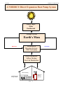
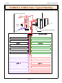
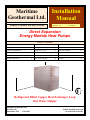
Maritime
Geothermal Ltd.
Installation
Manual
NORDIC® models EM (DX) 45-55-65
Revision 1.5
17-Feb-00
Direct Expansion
Energy Module Heat Pumps
Table of Contents
Heat Pump System Requirements .....
3
Safety Controls ………...
14
Trouble Shooting Guide ..........
21
Conceptual Overview ………
5
Starting the Heat Pump …….
15
Performance Curves ………..
24
Technology Explanation ……..
7
Component Layout ................
17
Setting the Aquastat ………..
27
Installing DX linesets ..................
11
Dimensions & Piping Layout
19
Electrical Schematic ..........………. 29
Inside Installation ………………….
12
EM Internal Schematic
20
Electric Block Diagram …...
Domestic Hot Water ...........................
13
Min. Circuit Ampacity
20
Warranty ............................………. 31
30
Refrigerant Filled Copper Heat Exchanger Loop
Hot Water Output
Maritime Geothermal Ltd.
P.O. Box 413
Petitcodiac, N.B.
E0A 2H0
Email: [email protected]
www.discribe.ca/nordic
17-Feb-00
Maritime Geothermal Ltd.
A NORDIC® Direct Expansion Heat Pump System
Energy Input:
Solar
Geothermal
Storage System:
Earth’s Mass
HEATING
Extraction &
Rejection System:
“EM” heat pump
COOLING
Heat Distribution:
Infloor Heating
Fan Coil Distribution
Infloor Heating
Fan Coil
Ducted
Systems
NORDIC® DX
Energy Module
Page .... 2
Maritime Geothermal Ltd.
17-Feb-00
NORDIC® EM (DX) System Prerequisites
1.
2.
3.
4.
There are four specific parts or sub-systems to a EMDX heat pump installation:
The source of energy ............................................................... Solar & Geothermal
The storage media ................................................................... The Earth’s mass
Converting the energy to a useable form ................................... Heat Pump
Distributing the heat ..................................................................Hot Water / radiant slab – fan coils
Horizontal Loop Fields
The
successful
application of a
EMDX heat pump
depends on sizing
the machine correctly for the
home or area to
condition and providing
enough
land area or volume of earth from
which to extract or
reject heat.
EMDX
heat
pumps react with
the earth much
like a conventional reversing
heat pump and closed loop plastic earth heat exchanger.
Heat that is available to the unit must travel through the earth
and therefore the conduction capability of the earth in the location of the heat exchanger is very important. A unit used
primarily for heating will have no problem with conduction
and heat transfer since it will be cooling the loop during heating mode. Cooling the soil draws moisture towards the coils
since they are colder than the surrounding ground. Horizontal
loop fields should be laid out so that the copper coils have
good cross-sectional influence on the minimum areas listed in
Model
# of
Loops
Area
Req’d
Trench
Layout
EMDX-45
(3) x 106
750 m²
1.3 x 53 m
EMDX-55
(4) x 106
930 m²
1.3 x 53 m
EMDX-65
(5) x 106
1160 m²
1.3 x 53 m
Table 1. As a general rule, wider spacing between the loops
so that they do not influence one another, will result in improved performance of the heat pump.
Unless you are sure there will be sufficient moisture present in the loop field area during the summer, a soaker hose
is recommended in all horizontal trench systems which will
used for air conditioning purposes.
Vertical Bore Systems
Vertical bores (76 mm x 30 m holes) provide an alternate method of installing a EMDX unit. A high water table in
Nordic® EMDX-45 will heat up to 140 m²
Nordic® EMDX-55 will heat up to 200 m²
Nordic® EMDX-65 will heat up to 260 m²
Assuming at least R-20 walls and R-40 ceiling
the borehole area (6 to 9 m) will insure that there is adequate
conduction with the earth and although the loop length per ton
is shorter than the horizontal design, the vertical orientation
and moisture in the boreholes provides very uniform conduction both winter and summer.
Note: These are minimum loop field requirements
based on an earth temperature of 7° C.
Table 1
Page .... 3
17-Feb-00
Maritime Geothermal Ltd.
NORDIC® EMDX Series Typical Plumbing
HOT Water OUT to home
Domestic
HOT
Water
Tank
Check
Valve
DX copper lines to outdoor loops
Page .... 4
Maritime Geothermal Ltd.
17-Feb-00
Energy Machines are superior to a
built-up system in the following ways:
Introduction to EMDX Technology
Direct earth coupled heat pump or “EMDX” heat pump is
one that has its refrigerant evaporator / condenser in direct
thermal contact with the earth from which heat is either extracted from during the heating mode or introduced to during
the cooling mode of operation.
1. Installed first cost is cheaper.
2. Building controls are simpler requiring less control
points.
3. Higher efficiency.
4. Hotter output temperature.
5. Year around domestic hot water capability.
6. Fewer moving parts - less maintenance.
7. Simple integration to an infloor heating system.
8. Back-up heat built in.
9. Stainless Steel storage tank.
10. Accurate temperature regulation.
Energy Machine Overview
As a result of direct urging from the engineering community,
Maritime Geothermal Ltd. has developed a unique new heat
pump solution specifically targeted at buildings which employ
infloor heating as the primary energy distribution system in
the building.
The need for an integrated package liquid-to-water or DX®to-water heat pump became apparent as mechanical engineers
who were designing the buildings found that the complexity
of setting up a mechanical room with suitable heat pumps,
circulator pumps, storage tanks, aquastats and other controls
seemed to pose a confusing demand on the installation contractors, plumbers and electricians.
1. Cost of purchasing the individual components and building
the mechanicals on site are higher than purchasing an integrated package such as the NORDIC® EM.
2. Costs associated with the control points in a building management system are also reduced since the machine only has
to be put in the "ON" or "OFF" mode requiring 1 point. The
energy machine operates all its internal pumps and circulators
automatically.
This complexity usually required repeated consultations on
site with the designing engineer and various tradesmen involved in carrying out the heat pump installation and with
companies involved in integration of the building management system.
3. Because the condenser of the heat pump is built into the
distribution tank, there is no need for an intermediate water
loop and associated pump system. This integration saves the
first cost of the circulation pump and the costs of operating
and maintenance on the pump over the years.
To address this situation Maritime Geothermal Ltd. Designed
the "Energy Machine" with all mechanical components required to mate successfully with an infloor heating system
built into the heat pump enclosure. The plumber need only
connect the supply and return to the floor header system and
the electrician makes a single wiring connection to the unit
for heat pump, circulator pumps and back-up electric heat.
4. The maximum output water temperature can be up to 52°C
(125°F) whereas a conventional water-to-water heat pump
will normally have a maximum output temperature of 46°C
(115°F).
An Energy Machine includes the following components.:
•Compressor
•Earth heat exchanger or provision for DX connection to the
ground.
•Insulated 40 gal. 316 SS distribution tank with integrated
refrigerant condenser and domestic hot water generator.
•Expansion tank, PRV, Boiler feed valve, pressure gauge.
•Electronic 2-stage aquastat.
•12 kw back-up heat
•Floor distribution circulator pump (Standard Taco® 0011 or
you spec head and volume).
•All controls prewired and ready to use.
With a typical water-to-water HPmost of these components
were outside the heat pump and had to be procured and installed by the plumber.
5. A conventional heat pump can only supply hot water during regular floor heating cycles unless there is an auxiliary
heat exchanger installed. The EM has a heat exchanger embedded in the tank which can produce domestic hot water
year around.
6. The EMDX has fewer moving parts than a conventional
heat pump and requires no servicing or maintenance of any
kind.
7. A two point connection to the floor header system is all
that is required.
8. External back-up boiler or electric hot water tank is not required since the EM tank is equipped with 9-15 Kw of back
up electric heat prewired and activated as the second stage of
a 2-stage digital aquastat.
9. The integrated storage tank is fabricated from type 316
Stainless Steel which will last the life of the building.
10. The EM is controlled with a digital 2 stage thermostat
with individually adjustable setpoints and differentials. First
and second stages will not overlap unless set to do so.
Page .... 5
17-Feb-00
Maritime Geothermal Ltd.
NORDIC® Vertical EMDX - Typical Loop design
NOTE:
Layout for one borehole shown
below. Actual installation requires one borehole per ton.
(I.E. (3) holes for a EMDX-45,
(4) holes for a EMDX-55 and
(5) for a EMDX-65
NORDIC® DX
“Energy Module”
Heat Pump
Liquid Line
Vapor Line
Trench
2m
•
•
Insulate liquid line
to here
•
35 m max.
•
Spacers
•
•
•
•
Pinch around pipes
and silver braze.
Keep pipes up 13
mm off bottom to
insure good flow.
•
NOTES:
Drill vertical bore to a depth of 30 to 35 m.
Pre-assemble or construct on site the dual (9 and 13 mm) piping assembly required. Seal both ends and pressurize with 1000 kPa nitrogen for
leak checking. Silver brazing a schrader valve in the end of the 9 mm
line will allow gauge checking for loss of pressure.
Check for leaks with soap suds. After a minimum 2 hr waiting period,
recheck the line for loss of pressure. If the temperature of the loop
hasn’t changed then the pressure should be same as it was originally.
Insulate both liquid lines and vapor lines from the heat pump to the well
head unless in separate horizontal trenches. Vapor lines in separate
horizontal trenches need only be insulated from 3 m out in the trench to
the basement wall. Liquid lines must be insulated from the heat pump
to approx. 1 m down the drop pipes in the vertical boreholes.
Install spacers to keep the pipes separated as far as possible from one
another in the boreholes.
Install 30 to 35 m of dual tubing (13 mm vapor & 9 mm liquid). Recheck pressure on lines. Secure pipes through opening in borehole
head. Backfill with pea gravel to 10 m from top. Seal hole with bentonite clay from 10 m to surface.
Most commercial installations will require tremie grouting of the borehole from bottom to top with bentonite with 28 to 30% solids.
Install linesets from well heads in horizontal trenches to heat pump in
building. Silver braze all joints with 5% silver solder using dry nitrogen
to purge the system. When all joints are complete, pressurize the entire
system with 1000 kPa nitrogen and recheck for leaks. Vacuum until
system stays below 500 microns for five minutes after vacuum pump
has been shut off.
Charge the prescribed amount of refrigerant through the high side
schrader valve located on the front of the machine.
22 mm Stub Cap (Copper)
Page .... 6
Maritime Geothermal Ltd.
17-Feb-00
Refrigeration Cycle
The general refrigeration cycle of our EMDX machine is
similar in nature to a conventional water-to-air or water-towater heat pump in that there exist a compressor, expansion
device, reversing valve, and refrigerant-to-air heat exchanger.
Conventional technology concerned with heat pumps relies upon the transfer of heat from the ground by means of a
secondary heat exchanger system and working fluid, e.g., water, which is pumped to the geothermal unit located in the
heated structure. The conventional heat pump has it’s own
internal primary heat exchanger which extracts heat (heating
mode) or rejects heat (cooling mode) from this water, which
is then pumped back to the earth to be reheated or cooled.
EMDX systems similarly use a ground coil system, however, the working fluid is a refrigerant and the copper groundloop is the primary heat exchanger. Such geothermal heat exchange is an efficient and effective way of achieving heat exchange in heating and air conditioning systems, and especially
heat pump type systems. Since the ground temperature is relatively constant at 7 o. at a depth 2 m below the frost line, the
available heat is constant.
The elimination of the secondary earth heat exchanger
(typically plastic in nature) and its associated working fluid
reduces the temperature difference required between the
ground and the evaporating refrigerant yielding a higher suction pressure than a conventional system under similar circumstances and thus a higher efficiency.
Many attempts have been made in the past to develop successful direct coupled heat pumps for residential and commercial uses. These attempts have failed adequately to meet a
number of requirements associated with an economically and
functionally viable system. Some of the shortcomings included:
1. Inadequate oil return to the compressor primarily in the
heating mode.
2. Inadequate evaporator length and spacing for properly
extracting heat from the earth resulting in low capacity
and low efficiency of the systems.
3. Refrigerant charges in the range of 10 times greater than
a similar capacity conventional geothermal heat pump.
4. Approximately 3 times as much refrigerant required in
the cooling mode as is required in the heating mode.
5. Lack of a proper means to store additional refrigerant required during the cooling operation but not needed during
the heating mode.
6. Inefficient and ineffective method to account for vastly
varying condenser capability depending on ground temperature.
7. Difficulty in providing an easy to install system of earth
exchanger loops.
107 m per ton of 13 mm OD copper tubing. A 3 ton system
would have 3 such loops working in parallel during the heating mode. Refrigerant charge had been determined to be 1.8
kg. of refrigerant per loop. These 13 mm copper loops maintain sufficient velocity at all times to insure adequate oil return. During cooling mode the machine automatically selects
one or more loops based on discharge pressure to act as the
condenser. As the discharge pressure builds to a predetermined point, the on-board computer selects the most appropriate combination of groundloops to dissipate the heat at the
lowest cost to the homeowner. By intelligently controlling the
manner in which the condenser is utilized our total system
charge does not have to be altered nor does an excess charge
have to be stored anywhere.
EMDX Better than Current Technology
There are several advantages of “EMDX” technology
that are superior to conventional geothermal heat pumps of
both the “open loop” and “closed loop” variety. Listed below
are some of the reasons why “EMDX” technology is becoming more attractive to Homeowners, Dealers and Utilities.
More Reliable.
•
•
•
•
Fewer parts to the system.
Does not require a supply and return well.
Does not require a well pump or circulation pumps.
No water heat exchanger and associated valving to corrode, freeze and break.
More Efficient
The direct expansion principle allows the refrigerant to
come directly into contact with the earth, separated only by
copper tubing. During winter, maximum heat transfer takes
place at higher temperature than conventional groundloop
technology without the maintenance and electrical cost of circulation pumps.
Less Maintenance
Only a sealed refrigeration circuit to maintain.
The NORDIC® solution has been to start with a clean
new concept and to design a unit from the ground up. We
started by developing an evaporator system that would yield
the best performance to pressure drop factor and which would
impact enough area to maintain a minimum suction pressure
above 276 kPa The current horizontal groundloop comprises
More Versatile
“EMDX” systems can be installed in a more confined area
than a conventional groundloop system, primarily because the
heat exchanger coil is much more efficient at transferring heat
Page .... 7
17-Feb-00
Maritime Geothermal Ltd.
Piping Layout of Vertical Style DXW Vertical Loop
HOME
Page .... 8
Maritime Geothermal Ltd.
17-Feb-00
to the refrigerant than a plastic earth exchanger. Normal loop
lengths for a “EMDX” machine are nominally 107 m per ton
as opposed to 140 to 150 m per ton for a plastic earth exchanger.
Similarly, vertical systems require only a 75 mm borehole
to a normal depth of 30 m per ton.
side to the filter rack side of the heat pump. Laying the
wooden pieces in this manner will give the best support since
they will be at right angles with the internal steel compressor
and heat exchanger supports.
Materials
supplied
by NORDIC®
Easier to sell
Systems can be quoted more accurately and easily since
there is less outside subcontracting involved.
Excavation or drilling contractors know in advance what
is required and can quote definite prices whereas with well
drilling for open loop systems, the well price may eliminate
the sale entirely.
Installation Instructions
Unpacking
When the heat pump reaches it's destination it should be
unpacked to determine if any damage has occurred during
shipment. Any visible damage should be noted on the carrier's
freight bill and a suitable claim filed at once.
The heat pump is strongly constructed and every effort has
been made to insure that it will arrive intact, however, it is in
the customer's best interest to examine the unit thoroughly
when it arrives.
Optimum Placement
The location of liquid-to water heat pump inside the
home should be determined by:
1. The ease at which piping runs can be connected to the
infloor heating headers on the output side of the
unit.
2. Space availability in a mechanical room for the hot
water distribution tank and associated pumps etc.
3. Ease of access to the water well supply and discharge
lines or groundloop lines.
If possible the four main service doors should remain clear
of obstruction for a distance of .6 m so that servicing and general maintenance can be carried out with a minimum of difficulty. Raising the heat pump off the floor a few inches is
generally a good practice since this will prevent unnecessary
rusting of the bottom panel of the unit.
We recommend that the heat pump be placed on a piece of
50 mm Styrofoam covered with 6 mm plywood. The Styrofoam will smooth out any irregularities in the cement floor
while the plywood will distribute the weight of the NORDIC® unit evenly over the Styrofoam. This process will also
deaden the compressor noise emitted from the bottom of the
cabinet.
As an alternative, several pieces of 50 mm lumber can be
placed under the unit running from the electrical connection
NORDIC® supplies the EMDX
heat pump with
all internal valving and headering
preassembled, pressure tested and
ready to be installed to the customers infloor system and underground copper exchanger loops. The underground coil assemblies can be purchased with the unit – pre-tested and
sealed with 700 kPa nitrogen pressure. A EMDX system may
comprise from 2 to 5 underground loops. One loop is required
for each nominal "ton" of compressor capacity. The standard
loops are 13 mm OD type “L” or “K” copper tubing. When
the dealer unpacks the coils the integrity of the loops can easily be checked by attaching a suitable pressure gauge to the 6
mm schrader valve on the coil assembly. The pressure read at
room temperature should be approx. 700 kPa (+- 30 kPa) If a
loop is not within this tolerance, it should be set aside for retesting or returned to NORDIC® for replacement. Under no
circumstances should a copper groundloop be used if there is
any question that it may not be pressure tight.
The EMDX heat pump
unit has been high pressure tested for leaks and
has a holding charge of
200 kPa (nitrogen) when
the dealer receives it.
Materials you will
need (inside)
A lineset is required to
connect the heat pump to
the underground coils
which will be installed outside the structure. This lineset consists of one 9 mm liquid line and one 13 mm gas line for each
"ton" or loop installed. The dealer will be required to silver
braze (5% silfos) the required indoor linesets from the point
of entry to the basement or installation area to the heat pump.
Horizontal Trench Requirements
The EMDX heat pump requires one ground coil or "loop"
per nominal ton of capacity.
Trenching for the EMDX heat pump can be best accom-
Page .... 9
17-Feb-00
Maritime Geothermal Ltd.
NORDIC® EMDX Horizontal Trench Design
Page .... 10
Maritime Geothermal Ltd.
17-Feb-00
plished with a tracked excavator equipped with a 1 to 1.3 m
bucket. If a wider bucket is available and you can afford the
extra cost, the trenches could be wider for improved performance. The object, of course, is to allow the copper loops to
contact earth which has not been influenced by the proximity of another loop. The trenches are dug from 1.5 to 2 m
deep to a total length of 55 m. Each of the EMDX loops is
107 m long and when laid in the form of a U down each side
of the trench the turn at the end will occur at 54 m allowing
for a small degree of error by the excavator operator. Take
special care that the bottom of the trench is kept as smooth as
possible to reduce the chance of pinching or crushing the copper tubing when backfilling the trench. If rocky conditions are
encountered it is recommended that the bottom of the trench,
especially the corners where the pipe will lay, be covered by
hand with limestone tailings, or some other heavy dense material to provide a relatively smooth resting place for the copper pipe. Unlike plastic pipe, the copper tubing will stay
where you put it when unrolled rather than arguing with you,
as plastic does, on a cool day. Once the pipe has been unrolled and placed, backfilling by hand to a depth of 152 mm
Entering dwelling
The copper groundloops must enter the dwelling at some
location typically through the concrete foundation just above
the poured floor. An alternate method would be to run the
pipe (insulated) up the outside wall making a 90 degree turn
above ground and entering the dwelling between the floor
joists just below the first floor. These pipes should be insulated with a minimum of 13 mm closed cell weatherproof insulation. There will be two 13 mm OD copper tubes for each
nominal ton of capacity of the heat pump being installed. For
example a 3-ton unit would have 3 groundloops and thus 6
ends to go through the concrete wall. We recommend that you
drill these holes to a diameter large enough to allow for the
insertion of a plastic sleeve, (see drawing ) and the tubing
with it's insulation jacket. Suitable measures must be taken to
seal the installation from water penetration before the trench
is backfilled.
Unrolling & Placing the Tubing
with fill as described above will ensure that the pipe is protected from falling rock etc. during the machine backfilling
procedure.
Other excavating devices such as a ditch-witch (chain digger) or a regular back-hoe can be used if ground conditions
permit however you will have to dig a U shaped trench with
spacing 2 to 3 m. We have found that the greater speed of the
tracked excavator in most soil conditions and the fact that you
only have to dig one trench (which is excellent width for a
man to work in) more than compensates for it's extra rental or
operational costs.
An alternative technique for burying the underground copper tubing would be to dig a large shallow pit with a bulldozer. This pit would have to be large enough to accommodate all the loops required in the system. The copper tubes
should have a spacing of at least 2 m minimum. A wider spacing would lead to slightly greater efficiency.
Each 15 m roll of tubing is taped both individually and to
the next roll in the group so that at any one time only 15 m of
the 107 m is free to unroll. This allows for easier unrolling
and prevents kinking the pipe. Observe how the taping is done
so that you know which side of the loop to start unrolling
first.
To begin, unroll approximately 4 m of copper tubing.
Slide three 2 m lengths of armaflex closed cell insulation with
wall thickness of at least 13 mm over the end of the tubing
and insert it through the plastic sleeve of hole # 1 approximately 20 cm into the basement. It is good practice to label
this line "loop 1 - gas" to identify it when interconnecting
linesets inside the building. Unroll the copper tubing down
one corner of the trench. When 53 m of tubing has been laid
out make your turn and proceed back the other side of the
trench to the foundation of the building. Slide two 2 m lengths
of armaflex insulation onto the tubing and insert the stub end
through hole # 2 in the wall to match the other end of the
loop. Label this end of the line "loop 1 - liquid" so that the
complete loop can be identified later. Manually backfill the
loop with fill to a depth of 15 cm for protection during the
machine backfill process. Duplicate the process described
above applying labels to identify the two ends of successive
loops (loop 2,3,4 etc.) until all required loops are in place.
Insulation Placement Near Foundation
It is important to apply closed cell insulation to the copper
groundloops as they come within 3 m of the building to prevent the possible build up of ice near the foundation of the
home. Applying 13 mm wall closed cell waterproof insulation
to the tubing as described above will insure that very little
heat is absorbed from the ground near the basement wall thus
avoiding possible frost damage to the structure.
Page .... 11
17-Feb-00
Maritime Geothermal Ltd.
Horizontal EMDX Loop Field (Plan View)
Page .... 12
Maritime Geothermal Ltd.
17-Feb-00
Pressure testing linesets
Using the 6 mm schrader valve supplied on each loop the
installer can again check the pressure on each lineset with his
refrigeration gauge set before releasing the pressure and cutting the loop stubs coming into the basement to the proper
lengths.
Interconnecting tubing
Once the outside loops have been installed it is necessary
to interconnect the "gas" and liquid lines of each loop coming
into the building to its corresponding line on the heat pump.
Each set of two pipes is labeled on the EMDX heat pump as
"loop 1 liquid", "loop 1 vapor", etc. depending on the tonnage
of the heat pump. The larger of the two pipes is the "gas" line
(13 mm OD) while the smaller line is the "liquid" line (9 mm
OD). The dealer must install a 13 mm OD "gas" line from
each of the gas lines on the heat pump to the corresponding
gas lines of each groundloop. Similarly a 9 mm OD "liquid"
line must be run from each heat pump "liquid" line to the corresponding liquid line of each groundloop.
Note that there is a transition in size from 9 mm to 13 mm
as the liquid line attaches to the groundloop stub coming into
the basement. A suitable reducing coupling can be purchased
from any refrigeration wholesaler.
The tubing used for this procedure must be refrigeration
tubing (cleaned & dehydrated) suitable for the job. Every effort must also be made to insure that the tubing does not become contaminated during installation. We recommend that
caps be placed on the open ends of tubing immediately after
cuts are made and that these caps are only removed after all
bends have been made and the pipe fixed in its permanent location ready to make the silver soldered joints. It is very important to keep a refrigeration system perfectly clean and dry
therefore removing the caps just prior to silver soldering will
insure that the tubing is exposed for a minimal time to the atmosphere and the associated moisture contained therein.
Insulating linesets
All tubing inside the basement must be insulated with 9
mm wall armaflex or equivalent insulation to prevent condensation and sweating during winter operation.
Silver soldering linesets
Once all the tubing runs have been routed, insulated and
fastened in place the caps can be removed, couplings applied
(or alternately the tubing can be "swaged") and the joints silver soldered with 5% silfos. NORDIC® absolutely requires
that dry nitrogen be bled through the system during all
silver soldering procedures so that no oxidation occurs on
the inside of the copper tubing.
Vacuuming system
made by the installer checked for leaks using soap suds or
some other technique that the installer feels comfortable with.
It is important not to bypass this step since vacuuming the
system with a leak will be impossible and attempting to do so
will introduce moisture to the system making the process take
much longer to vacuum after the leak has been found and repaired.
Vacuum the system until the reading on an electronic vacuum gauge stays below 500 microns for a period of 5 minutes
after the vacuum pump is shut off and the system sealed.
Charging system
Once the system has been vacuumed refrigerant can be
added by weighing in 1/3 of the prescribed refrigerant charge
into the low side of the system. Start the heat pump in the
heating mode and continue to add refrigerant as a liquid at a
rate of no more than .5 kg per minute until the prescribed
charge is reached.
Alternately, before the machine is started, the entire
charge can be weighed into the system through the high side
schrader valve.
Hot Water Connections
Connection to the hot water generator feature of the
heat pump is accomplished by teeing into an electric or oil
fired hot water tank with a capacity of 180 litres minimum. A
typical piping diagram is shown elsewhere in this manual. Be
sure to note the position of the check valve and the direction
of water flow.
One should be sure the tank is filled with water and
is under pressure before activating the heat pump to insure
proper lubrication of the circulator pump. Slightly loosen the
copper union on the hot water discharge pipe to allow air to
escape from the system before the unit is started. This step
will make certain that the water circulator is flooded with water when it is started. Since the pump is water lubricated,
damage will occur to the pump if it is run dry for even a short
period. The union on the discharge water line may have to be
purged of air several times before good circulation is obtained. A hand placed several feet down the line will sense
when the water is flowing.
The thermostats on the hot water tank should be set
to 38 °C. since the heat pump will transfer energy, via an internal heat exchanger, from the main internal tank normally
maintained at 45°C. By setting the tank thermostats as described, the heat pump will try to keep the tank above the
cut-in point of the electric element settings thus generating
hot water from the heat pump only. During periods of high
demand, the electric elements could energize to help make hot
water.
Safety Controls
The NORDIC® heat pump has two built in safety controls
which are designed to protect the unit from situations which
could damage it.
When silver soldering is finished the entire system should
be pressurized to 700 kPa with dry nitrogen and all joints
Page .... 13
1. Low pressure control
The low pressure control is designed to shut the unit down
17-Feb-00
Maritime Geothermal Ltd.
NORDIC® EMDX Pit Heat Exchanger Layout
ONE LOOP PER “TON” REQUIRED
3m
3m
3m
Diagram at left shows another possible
configuration for a horizontal DX piping
system.
• Each loop should encompass about
230 m2 to 325 m2 of land area per
“ton” of heat pump.
• Each loop consists of 107 m of 13
mm copper tubing.
• The “pit” could be a excavated area
or an existing area which needs to be
filled as part of general excavation.
• Loops should be buried approximately 2 m underground for best
performance.
Example:
Nordic DX-45 should have (3)
loops as shown at left, a DX-55
(4) loops and a DX-65 (5) loops.
25 m
Other configurations would work as well
such as a 15 x 15 m pattern or a 18 x 14
m etc.
The object is to encompass at least the
minimum area mentioned above with
spacing no closer than 2.5 m between
any two pipes.
Page .... 14
Maritime Geothermal Ltd.
17-Feb-00
if the refrigerant evaporating pressure drops below 20 psig.
Some possible causes for a trip out on low pressure are:
1.Ruptured or broken groundloop coil.
2.Low refrigerant charge.
3.Other refrigerant leak.
2. High pressure control
The second safety control is a high pressure safety limit
which monitors compressor discharge pressure. This device
will not normally trip unless:
1. There is low or no water in the internal tank.
2. Aquastat is set too high. (Above 53°C)
If either of these controls trips it will activate a lock-out relay
which prevents the unit from restarting until power to the control circuit is broken (by opening the 24v circuit between “R“
and “T“) or the electrical supply to the unit is broken by opening the heat pump breaker and then closing it again. If one of
these controls trips there is a serious problem with the system
and it must be rectified if the unit is to maintain good service.
•
•
1.
2.
3.
4.
5.
Electrical
The NORDIC® unit is supplied with an opening for 19
mm conduit nipple on the right side of the unit. An additional
13 mm knock-out is also supplied to accommodate accessories which may be attached to the heat pump's relays (such as
circulator pumps etc.). Above the accessory knock-out is another 9 mm hole for the thermostat wire which controls the
circulator pump. A wiring diagram is located on the electrical
box cover for quick reference and although the connections to
be made are quite simple, Maritime Geothermal Ltd. recommends that a properly qualified electrician be retained to
make the connections and wire the thermostat.
Starting the Heat Pump
BEFORE starting the heat pump the following areas
should be rechecked to assure proper operation.
1. Check all high voltage field wiring and electrical connections inside the control box for good connection.
2. Turn on the main power switch. The Ranco® 2-stage aquastat stage1 setpoint is set to 110°F with a 10°F differential from the factory. Stage2 of the aquastat is factory
set at 100°F with a 5°F differential. This means that the
unit will cycle on stage1 and stage2 when first powered
up.
3. Turn on the water supply to the hot water lines and check
all plumbing for leaks.
4. Check the hot water tank to be sure it is filled with water
before energizing the circuit. Slightly open the pressure
relief valve on the top of the hot water tank to make sure
that all air is out of the system and the circulator pump is
flooded with water.
5. Vacuum out any dust and debris that may have collected
in the unit during installation.
6. Make sure the proper time-delay fuse or breaker has been
installed in the electrical panel.
7. Have the following tools on hand and know how to use
them.
• A refrigeration gauge set.
6.
7.
An electronic or other accurate thermometer.
An amprobe.
Connect your refrigeration gauge set.
Turn on the power to activate the system. The Ranco aquastat will display the temperature in the tank and if below the setpoint – “S1” and “S2” will be displayed in the
LCD window and the compressor will start.
Observe the readings on the high and low pressure gauge
set. With an initial earth temperature of 7° to 10° C the
suction pressure (blue gauge) should be approximately
315 to 400 kPa while the head or discharge pressure (red
gauge) should be in the area of 1350 to 1900 kPa. Record
this information on the warranty test card.
The temperature on the aquastat should show a steady
rise as the internal distribution tank warms up. As the
temperature rises above the electric back-up setting, “S2”
will disapear from the display and only the heat pump
will be operating.
If you wish to operate the unit without the electric backup coming on then switch the internal electric heat
breaker off.
At the electrical disconnect switch place the amprobe
jaws around the supply wires and record the current in
each conductor and record this current.
When the tank comes up to temperature you can open
any valves on the hot water supply lines and the unit is
ready to operate.
General Maintenance
As with any piece of equipment there will eventually be
some maintenance to be done on the heat pump however a
EMDX heat pump is relatively maintenance free and only one
item will need attention as follows:
⇒ Check contactors for burned or pitted points.
Theory of Operation
The EMDX heat pump utilizes a typical vapor compression refrigeration cycle similar to many other common appliances. The only difference between a Direct Expansion heat
pump and a conventional geothermal unit is the fact that the
DX unit has it’s heat exchanger embedded in the ground. The
EM machine also incorporates the condenser coil directly inside the internal hot water buffer tank
Due to some engineering obstacles involved with remote
parallel evaporators some special equipment and techniques
which are described below are required to allow such a system to work effectively. Some text below may also describe a
heat / cool system. If your system is heat only or heat and hot
water then skip over the cooling description sections.
4-Ton System Description Heating Mode
All NORDIC® EMDX systems utilize multiple earth
loops to transfer heat to and from the ground. One loop per
ton of capacity is normally required and during the heating
mode all the loops are active.
Liquid refrigerant passes from the air handler section
through the bi-flow filter-drier and through the cooling TX
valve which is fully open by virtue of it’s equalizer line being
Page .... 15
17-Feb-00
Maritime Geothermal Ltd.
connected to the common suction inlet line and it’s controller
bulb attached to the vapor inlet line (hot in heating mode) of
the air handler. Liquid refrigerant then travels towards the liquid line header, solenoid valve and check valve assembly. Solenoid valve “A” is a normally open valve and is de-energized
during the heating mode thus refrigerant can travel unrestricted through the heating check valves (B, C, D, E) towards
the inlet of all the heating TX valves.
Vertical DX Borehole With Copper “U” Tube
Each heating TX valve is equipped with a small bypass
capillary tube which allows approximately 1/2 ton of refrigerant to flow regardless of the position of the TX valve. This
by-pass is intended to perform 2 functions:
• Limits the amount of hunting done by the TX valve due
to the long evaporator length.
• Prevents the heat pump from tripping out on a high pressure limit if all the heating TX valves decide to close at
the same time.
The TX valves control the flow of liquid refrigerant to it’s
loop by virtue of the sensing bulbs being attached to each
respective return vapor line and all the equalizer lines connected to the common suction inlet line. The sensing bulb of
each TX valve is located just below the connection to the 3way valves on the gas line header assembly.
Enough extra tubing has been supplied to
reach into the building when temporary
plastic casing is removed.
units so equipped, where a small portion of its heat is removed in the production of hot water. The hot refrigerant then
enters the air coil where the refrigerant vapor is condensed by
the process of cool household air flowing across the air-torefrigerant coil. Further sub-cooling of the refrigerant liquid
takes place as the refrigerant reaches the bottom of the coil
and begins another cycle.
1. It allows the machine to switch from heating to cooling
mode without shut-off on it’s low pressure control since
refrigerant pressure is supplied to the intake of the compressor by the idle loops while the refrigerant is being
repositioned to operate in another loop or loops.
Excavate alongside each borehole so that the copper tubing can lay over into the trench.
The liquid refrigerant coming in contact with the warm
earth vaporizes to a gas and flows back to the heat pump via
the 13 mm OD copper return vapor lines. System oil is entrained in by the velocity of the return gas and is continuously
swept back towards the compressor. Refrigerant vapor normally picks up from 2 to 6°C superheat as it returns to the
heat pump. Refrigerant vapor enters the 3-way valve header
assembly at ports “F”, passes straight through the valve to
ports “G” where it exits to the vapor line header. From the
vapor line header the refrigerant gas enters the reversing valve
at point “H” and exits to the common suction line “I” where it
travels to the accumulator and onward to the compressor. Hot,
high pressure refrigerant gas enters the desuperheater coil, on
Once the refrigerant enters the groundloop(s) it condenses
giving up its heat and returns to its liquid state. Oil and liquid
refrigerant are swept along the underground copper lines back
to the liquid line header assembly where it flows through the
cooling check valve(s) connected to the respective liquid lines
and onward towards the cooling TX valve which meters refrigerant into the air coil as required. Liquid cannot enter any
of the other liquid lines because of the orientation of the cooling check valves nor can it enter the heating section of the
liquid line header by virtue of liquid line solenoid valve “A”
being energized (closed) while in the cooling mode.
Page .... 16
Maritime Geothermal Ltd.
17-Feb-00
EMDX Left
Expansion Tank
Domestic Water (In)
Domestic Water (Out)
Main Hot Water (Out)
Main Hot Water (In)
Liquid Lines
Vapor Lines
Expansion Valves
40 Gal. Stainless Distribution Tank
Electric Heat Elements (3 x 3KW)
EMDX Front Side
Ranco® 2-stage Digital Aquastat
Compressor Contactor (Right)
Electric Heat Contactor (Left)
Electric Heat Breaker (Left)
Compressor Breaker (Right)
Main Power Terminal Block
Floor Circulator
Compressor
Accumulator
Page .... 17
17-Feb-00
Maritime Geothermal Ltd.
NORDIC® Series EMDX-45-55-65-HW
Engineering and Performance Data
Feb 00
Page .... 18
Maritime Geothermal Ltd.
17-Feb-00
Revision 4.35
Color: Caissie Grey
Models: EMDX-45-65
Style: Horizontal
Maritime Geothermal Ltd.
EM Direct Expansion-to-Water Heat Pumps
Date: Feb 1999
Drawn By: G. Kaye
Title: Piping / Electrical & Dimensions
LEFT SIDE VIEW
Page .... 19
17-Feb-00
Maritime Geothermal Ltd.
Revision 4.35
Color: Caissie Grey
Models: EMDX 45-65
Style: Horizontal
Maritime Geothermal Ltd.
Energy Module DX Heat Pumps
Date: June 1998
Drawn By: G. Kaye
Title: Refrigerant Circuit Diagram
Heat Pump Electrical Service Requirements
Second row lists requirements with 9KW internal back-up heat installed
Model
EMDX-45-HW
EMDX-55-HW
EMDX-65-HW
Voltage
230/1
208/3
230/1
208/3
230/1
208/3
Min. Circuit Ampacity
21
61 with
Elec. back-up
15
50
28
64
20
53
34
70
23
56
Recommended Wire Size
8-3
3-3
10-3
6-3
8-3
3-3
10-3
6-3
6-3
3-3
10-3
6-3
TD Fuse or Breaker
40
70
20
60
40
100
30
60
50
100
30
60
Control Wire
18-3 thermostat wire (for all)
Page .... 20
Maritime Geothermal Ltd.
17-Feb-00
NORDIC® EMDX Heat Pump Trouble Shooting
Fault
Possible Cause
Compressor not Power Failure
operating
Verification
Recommended Action
Electric circuit test shows no voltage Check for blown fuse at heat pump’s
on the line side of compressor condisconnect box or blown fuse
tactor.
Disconnect switch open
Voltmeter shows no voltage on the
Determine why the disconnect
line side of the compressor contactor. switch was opened, if all is OK close
the switch.
Fuse blown
At heat pump disconnect box, voltmeter shows voltage on the line side
but not on the load side.
Replace fuse with proper size and
type. (Time-delay) type “D”
Check total load on system.
Low voltage
Voltmeter shows abnormally low
voltage (Below 210 v) at heat pump
disconnect switch.
Call power company.
Burned out motor
Ohmmeter shows no resistance beDetermine cause and replace motor.
tween common and run terminals or
between common and start terminals.
Note: Be sure compressor overload
has had a chance to reset. If comp. is
hot this may take several hours.
Thermal overload on compressor tripped.
Ohmmeter shows reading when
placed across R and S terminals and
infinity between C & R or C & S.
Make sure the internal overload has
had time to reset.
If windings are open or overload is
faulty, replace compressor.
Faulty compressor contactor. Voltage on line side with contactor
Replace contactor.
held closed, but no voltage on one or
both terminals on the load side.
Points pitted or burned.
Seized compressor due to
locked or damaged mechanism.
Compressor attempts to start but
Attempt to “rock” compressor free.
trips it’s internal overload after a few If normal operation cannot be estabseconds.
lished, replace compressor.
Faulty run capacitor.
Check with ohmmeter for shorts,
open etc.
Page .... 21
Replace if faulty.
17-Feb-00
Fault
Maritime Geothermal Ltd.
Possible Cause
Compressor not Open control circuit.
operating
Compressor
“short cycles”
Intermittent contact in electrical control circuit.
•
•
•
•
Thermostat not calling for heat.
High or low pressure limit open.
Lock-out relay energized.
Heat / Cool units only control
board shows hi or low pres. permanent lock-out.
Recommended Action
Locate open control and determine
cause. Replace faulty control if necessary.
Heat / Cool Units Only
Microcontroller board shows “RED”
high pres. or “GREEN” low pres.
lockout flashing or glowing steadily.
Normal operation except too frequent starting and stopping.
Check differential in aquastat is set
for at least 3°C
Refrigeration gauges show suction
pressure dipping below 138 kPa
Check refrigerant level. Add refrigerant slowly. Check for possible
leaks. Normal charge is 1.8 kg per
ton.
Faulty low pressure ctrl.
Refrigerant pressure control should
open on drop at approx. 138 kPa
Normal suction is 275 – 400 kPa
Control should reset automatically.
Heat pump can then be restarted by
resetting the lock-out relay or ctrl.
board. (Turn power off then back on)
Replace faulty control if it will not
reset.
Faulty TXV’s
Check individual suctions to verify
that each TXV opening and closing
cycle is approximately the same.
Replace TXV(s) if not operating
properly.
Aquastat setting too high.
Eg. Above 50°C (122°F)
TXV stuck closed
Filter drier plugged.
No or low water in tank.
Check for refrigerant flow through
TXV and filter.
Make sure tank is full of water and
not above 50°C (122°F)
Replace filter or TXV if required.
Fill tank with water.
Unit trips off on Low refrigerant level.
“LOW” suction
pressure
control.
HEATING
Unit trips off on
“HIGH” pres.
control.
HEATING
Verification
Page .... 22
Maritime Geothermal Ltd.
17-Feb-00
Fault
Possible Cause
DOMESTIC
HOT WATER
Insufficient hot
water.
Circulator pump not operating.
Heat pump not operating.
Switch set to “OFF”
Valves shut off
Use an amprobe to measure current Replace if faulty.
draw.
Observe any shut-off valves for location.
Blockage or restriction in the
water line or hot water heat
exchanger.
Check water flow and power to
Remove obstruction in water
pump. Check water lines for obstruc- lines. Acid treat the domestic hot
tion
water coil.
Thermostat (if equipped) is
open.
Check contact operation. Should
close at 40°C and open at 45°C.
Replace thermostat if faulty.
Disconnect switch open, or
breaker open in electrical supply to heat pump.
Check both line and load sides of
fuses or breakers. If switch or
breaker is open determine why.
Replace blown fuse or breaker or
close switch.
Electric
Elements in
Storage Tank
not operating.
Verification
Recommended Action
Electric element breaker inside Check voltage at elements with mul- Reset breaker.
electric panel of heat pump
timeter. Check for grounded or open
shut off.
element.
Second stage of aquastat on
hot water tank set too low.
Should be set at 38° to 40°C.
Visually inspect the setting.
Temporarily adjust the setting up to
see if the elements engage.
Readjust the setting to 40°C.
Trouble Shooting Tools
Dole flow control Valve
Refrigeration Gauges
Amprobe
Digital Thermometer
In-line Flowmeter
Page .... 23
The Dole® flow control is a simple, selfcleaning device designed to deliver a constant volume of water from any outlet
whether the pressure is 15 psig or as high as
125 psig. The controlling mechanism consists of a flexible orifice that varies it’s area
inversely with pressure so that a constant
flow is maintained.
17-Feb-00
Maritime Geothermal Ltd.
Performance Specification Sheets
Heating Mode
Soil
Model EMDX-45-HW
Btu's
Comp.
Comp.
Suct.
Disch.
Temp.
HAB
EWT
LWT
Flow
Out
Amps
Watts
Watts
COP
Pres.
Pres.
70
45163
100
109.9
10
59556
19.4
3640
4045
4.3
88
282
60
40104
100
108.9
10
53285
18.7
3489
3896
4.0
75
267
55
37560
100
108.6
10
51532
18.4
3393
3803
4.0
68
258
50
34335
100
108.1
10
48670
17.9
3296
3697
3.9
62
250
45
32607
100
107.6
10
45594
17.3
3178
3584
3.7
57
240
41
30635
100
107.3
10
43956
17.4
3129
3543
3.6
54
234
35
26674
100
106.3
10
38008
16.6
2963
3378
3.3
45
219
30
22677
100
106
10
35919
16.6
2877
3301
3.2
39
210
Water flow in IGPM Temperatures in °F
70000
60000
50000
40000
30000
20000
10000
0
70
60
55
50
45
41
35
30
41
35
30
Ground Temperature (Deg. F.)
COP Vs. Ground Temperature Model EMDX-45
Coefficient of Performance
Btu's per Hour
Btu Output Vs. Ground Temperature Model EMDX-45
5
4
3
2
1
0
70
60
55
50
45
Ground Temperature (Deg. F.)
Page .... 24
Maritime Geothermal Ltd.
17-Feb-00
Performance Specification Sheets
Heating Mode
Soil
Model EMDX-55-HW
Btu's
Comp
Comp.
Blower
Blower
TOTAL
Suct
Disch
Temp
HAB
EWT
LWT
Flow
Out
Amps
Watts
Amps
Watts
Watts
COP
Pres
Pres
70
60745
100
111.8
10
70897
23.0
4780
3.4
318
5089
4.1
84
302
60
50181
100
110.3
10
61739
20.7
4356
3.5
325
4673
3.9
72
276
55
46173
100
109.7
10
58374
19.5
4132
3.5
324
4447
3.8
65
262
50
42875
100
108.9
10
53868
18.8
3943
3.4
356
4288
3.7
60
250
45
38208
100
108.3
10
49602
18.4
3764
3.4
329
4083
3.6
54
240
40
35795
100
107.8
10
46611
17.6
3594
3.5
338
3923
3.5
50
230
35
31942
100
107.1
10
42399
16.5
3410
3.6
338
3738
3.3
44
220
30
29447
100
106.7
10
40126
15.9
3256
3.6
335
3581
3.3
41
212
Water flow in IGPM Temperatures in °F
80000
60000
40000
20000
0
70
60
55
50
45
40
35
30
35
30
Ground Temperature in Deg. F.
COP Vs. Ground Temperature - Nordic EMDX-55
COP
Btu Output
Btu Out Vs. Ground Temperature - Nordic EMDX-55
5.0
4.0
3.0
2.0
1.0
0.0
70
60
55
50
45
Ground Temperature in Deg.F.
Page .... 25
40
17-Feb-00
Maritime Geothermal Ltd.
Performance Specification Sheets
Heating Mode
Soil
Model EMDX-65-HW
Btu's
Comp.
Comp.
Blower
Blower
TOTAL
Suct.
Disch
Temp
HAB
EWT
LWT
Flow
Out
Amps
Watts
Amps
Watts
Watts
COP
Pres.
Pres.
70
62860
100
114.1
10
84730
31.8
6551
4.2
414
6965
3.56
80.4
274
65
60207
100
113.7
10
82080
30.5
6299
4.3
420
6719
3.58
74.7
266
60
56347
100
112.8
10
76542
29.2
5990
4.3
415
6405
3.50
68.2
255
55
50459
100
111.8
10
70659
27.8
5721
4.2
413
6134
3.37
62.8
245
50
46511
100
111.2
10
67164
26.7
5428
4.1
414
5842
3.37
57.2
234
45
42117
100
110.4
10
62200
25.4
5173
4.1
415
5588
3.26
52.4
224
40
38521
100
109.7
10
58167
24.1
4904
4.2
410
5314
3.21
47.5
215
34
33010
100
109
10
53759
23.0
4611
4.1
412
5023
3.14
41.9
207
30
30341
100
108.3
10
49725
22.2
4491
4.2
412
4903
2.97
38.8
203
Water flow in IGPM Temperatures in °F
Btu Output
Btu Output Vs. Ground Temperature - NORDIC EMDX-65
100000
50000
0
70
65
60
55
50
45
40
34
30
Ground Temperature - Deg. F.
COP Vs. Ground Temperature - Nordic EMDX-65
COP
4.00
3.00
2.00
1.00
0.00
70
65
60
55
50
45
Ground Temperature - Deg. F.
Page .... 26
40
34
30
Maritime Geothermal Ltd.
17-Feb-00
Ranco® ETC Thermostat Controls
The Ranco® ETC is a microprocstage1 cooling or heating mode.
essor-based electronic temperature
The LCD will display the current
control designed to handle the
mode, either C1 for cooling or H1
OFF/ON functions of the NORfor heating. Then press the UP or
DIC® EMDX unit. The ETC is
DOWN key to toggle between the
equipped with an LCD display
C1 or H1 designation.
which provides a constant readout
(NOTE: For purposes both
of the sensed temperature and a
stages of both aquastat are set to
touch keypad that allows the user
the H1 or H2 designation. )
to easily and accurately select the
STAGE 2
setpoint temperatures and differenStep 5– Press the SET key again to
tials for the first and second stages
access the stage 2 setpoint. The
of operation.
LCD will display the current setProgramming Steps and Dispoint and the S2 annunciator will
be blinking on and off to indicate the control is in
play
Step 1– To start programming, press the SET key
the setpoint mode. Then press either the UP key to
once to access the Fahrenheit/Celsius mode. The
increase or the DOWN key to decrease the setpoint
display will show the current status, either F for de- to the desired temperature.
grees Fahrenheit or C for degrees Celsius. Then
Step 6– Press the SET key again to access the
stage2 differential . The LCD will display the curpress either the UP arrow or DOWN arrow key to
toggle between the F° or C° desrent differential and the DIF 2 anignation. For closer regulation of
nunciator will be blinking on and
your PC temperatures we recomoff to indicate that the control is in
mend you program in the Fahrthe differential mode. Then press
enheit mode.
either the UP arrow key to increase
ETC Location
STAGE 1
or the DOWN arrow key to decrease the differential to the desired
Step 2– Press the SET key again
to access the stage1 setpoint.
setting.
The LCD will display the current
Step 7– Press the SET key again to
setpoint and the S1 annunciator
access the stage 2 cooling or heatwill be blinking on and off to ining mode. The LCD will display
dicate that the control is in the
the current mode, either C2 for
setpoint mode. Then press either
cooling or H2 for heating. Then
press either the up or down key to
the UP arrow key to increase or
the DOWN arrow key to detoggle between the C2 and H2 desEMDX
crease the setpoint to the desired
ignation. Press the SET key once
Electrical Box
more and programming is comtemperature.
plete.
Step 3– Press the SET key again
to access the stage1 differential. The LCD will disNOTE: The ETC will automatically end programplay the current differential and the Dif 1 annuncia- ming if no keys are depressed for a period of 30
tor will be blinking on and off to indicate that the
seconds. Any settings that have been input to the
control is in the differential mode. Then press eicontrol will be accepted at that point.
All control settings are retained in non-volatile
ther the UP arrow key to increase or the DOWN
arrow key to decrease the differential to the desired memory if power to ETC is interrupted for any reasetting.
son. Re-programming is not necessary after power
outages or disconnects unless different control setStep4– Press the SET key again to access the
Page .... 27
17-Feb-00
Maritime Geothermal Ltd.
Ranco® ETC PC Thermostats
8 ft. extension cable
Cover screws (4)
Temperature sensor
Circuit board
Mounting Holes
Locking switch
NOTE:
The temperature “sensor”
can be extended up to
400 ft. by cutting the sensor extension cable and
splicing 22 gauge (2 conductor) copper wire in
place.
Regular telephone wire
can be used for this operation.
Shown
Below
Conduit Opening
24v Power Connection
Stage 1 relay
Stage 2 relay
Stage 1
NC NO C
Stage 2
NC C NO
Page .... 28
Maritime Geothermal Ltd.
17-Feb-00
NORDIC® EMDX-45-55-65-HW Series - Schematic
208v/3ph/60Hz
Greyed Circled Items (Optional)
Page .... 29
17-Feb-00
Maritime Geothermal Ltd.
NORDIC® EMDX-HW Series Electrical Box
208v/3/60 Box – Heating & Domestic Hot Water Versions
NOTE (A)
Electric Heat Back-up is
An option which can be
activated or deactivated by
the customer by disconnecting the breaker as required. To disconnect permanently – remove wires
D, E & F at left.
Electric Heat
Breaker & Relay
A
E
F
D
Page .... 30
Maritime Geothermal Ltd.
17-Feb-00
LIMITED WARRANTY
MARITIME GEOTHERMAL LTD. warrants that the heat pumps manufactured by it shall be free from defects in materials and workmanship for a period of
(1) ONE YEAR after the date of installation or for a period of (1) ONE YEAR AND
(60) SIXTY DAYS after the date of shipment, whichever occurs first. In addition
MARITIME GEOTHERMAL LTD. warrants that the compressor shall be free of
defects in materials and workmanship for an additional period of (48) FORTYEIGHT MONTHS from said date.
MARITIME GEOTHERMAL LTD. shall, at it's option repair or replace any
part or parts covered by this warranty which shall be returned to MARITIME GEOTHERMAL LTD., transportation charges prepaid, which, upon examination proves
to be defective in materials or workmanship. Replacement or repaired parts and
components are warranted only for the remaining portion of the original warranty
period.
This warranty is subject to the following conditions:
1. The NORDIC® heat pump must be properly installed and maintained in accordance with MARITIME Geothermal LTD.'s installation and maintenance instruct
ions.
2. The installer must complete the “Installation Data Sheet”, have it endorsed
by the owner and return it to Maritime Geothermal Ltd. within 21 days after the installation of the unit.
3. It is the responsibility of the building or general contractor to supply temporary heat to the structure prior to occupancy. These heat pumps are designed to provide heat only to the completely finished and insulated structure. Start-up of the unit
shall not be scheduled prior to completion of construction and final duct installation
for validation of this warranty.
If the heat pump, manufactured by MARITIME GEOTHERMAL LTD. fails to
conform to this warranty, MARITIME GEOTHERMAL LTD. 's sole and exclusive
liability shall be, at it's option, to repair or replace any part or component which is
returned by the customer during the applicable warranty period set forth above, provided that (1) MARITIME Geothermal LTD. is promptly notified in writing upon
discovery by the customer that such part or component fails to conform to this warranty. (2) The customer returns such part or component to MARITIME GEOTHERMAL LTD., transportation charges prepaid, within (30) thirty days of failure, and (3)
MARITIME GEOTHERMAL LTD. 's examination of such component shall disclose to it's satisfaction that such part or component fails to meet this warranty and
the alleged defects were not caused by accident, misuse, neglect, alteration, improper installation, repair or improper testing.
Page .... 31
17-Feb-00
Maritime Geothermal Ltd.
Maritime Geothermal Ltd.
has the solution for all your
heating and cooling projects
Vertical
Liquid-to-Air
Liquid-to-Liquid
NORDIC
NORDIC
Horizontal Slim
Liquid-to-Air
Split Systems
NORDIC® — Environmentally sound solutions to
today’s Heating and Cooling needs.
Page .... 32