1
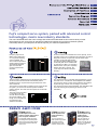
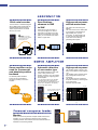
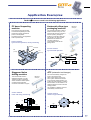
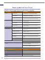
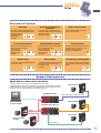
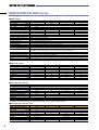
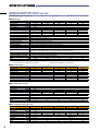
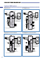
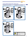
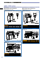
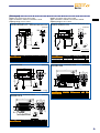
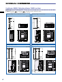
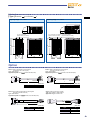
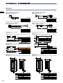
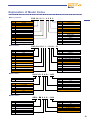
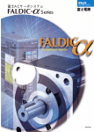
MEH 392a
●
2
Cubic type
Slim type
Having a drastically shorter
depth, the motor does not
remarkably protrude to the
rear of the machine when
mounted.
A small flange allows
the motor to fit into a
small area.
Fuji's compact servo system, packed with advanced control
technologies, meets new industry standards.
The new FALDIC-αseries has come onstage with enhanced fundamental functions and a variety of other
useful functions such as an easy-to-operate PC loader and real-time tuning of the mechanical systems.
These help shorten your setup time as well as improve your machine's performance.
Frequency response at
600Hz and a settling time
of 1 ms provide amazing
control capability. The
servo motor incorporates a
real-time tuning function to
automatically adjust the
gain even when the
moment of load inertia
fluctuates.
700Hz
5dB
-3dB
10Hz
100Hz
1kHz
The servo motor, equipped with a 16-bit serial encoder which
can be used for both incremental and absolute position
feedback systems, requires less wiring and keeps the motor
wow at low level.
The encoder connects with four cables: two for power and two
for signals. (To construct an absolute position feedback
system, however, two other lines are required to connect with
the battery.)
The motor can be operated
in combination with the
encoder without changing
the encoder settings, even
though such combination is
not specified as the
standard combination.
From the selection of a suitable servo motor capacity, to test
operation of the motor, maintenance and inspection, as well as
diagnosis of alarms, the personal computer loader helps
navigate you through all processes.
The servo amplifiers radiate less heat
horizontally and can be installed side
by side with very little or no clearance
between them. (If they are completely
fitted to each other, however, the
cyclic duty factor will be reduced to
80%ED.)
The servomotors are so compactly designed that they can be
mounted even in a small area. Servo amplifiers are available
in three types; velocity control, linear positioning, and rotation
angle index type. Choose one according to your needs.
The servomotors meet foreign standards. (The standard model
meets CE marking and is planning to achieve UL/cUL
standards.)
V type (Velocity)
L type (Linear motion)
R type (Rotation)
Servo amplifier for motor
velocity control using a pulse
train or speed command
Servo amplifier with
linear positioning
function
Servo amplifier with
rotation angle
indexing function
The amplifier rotates the motor
according to the specified pulse
train command or analog speed
command issued from the host
control unit.
You can construct a
linear positioning system
using such machine
components as a ball
screw or rack & pinion.
You can construct a
rotation angle index
system such as that for
an ATC, tool magazine,
or transfer unit.
●
3
16-bit serial encoder
The servomotor is standard-equipped
with a 4Mbps serial encoder that can
generate 65536 pulses/revolution.
These components are connected
with only four wires.
4wires
(to encoder)
* The absolute position feedback
system requires six wires,
including battery lines.
Specifications
common to 50W
to 5kW
There are two types of motors: a
cubic type (ranging from 100W to
2kW) with a short depth, and a slim
type with a small flange. Using both
types, you can select a motor with a
brake or a gear head.
Gear head
Servo amplifier can be
used for incremental
and absolute position
feedback
An absolute position feedback
system can be constructed by
connecting a battery to the servo
amplifier.
High-speed response
and low motor wow
The power rate of the slim type is
65kW/s.
The motor returns to the rated speed
by accelerating or decelerating in
approximately 2ms. (0.4kW
servomotor, no load at shaft end)
A 16-bit serial encoder keeps the
motor wow at a low level by
generating 65536 pulses.
Servomotor
Automatic detection
of servomotor type
The amplifier detects the motor type
(cubic or slim) and the motor
capacity. Therefore, you can operate
the motor simply by supplying power
to the amplifier.
- The servomotor and the servo amplifier
are ranked at the same capacity level.
- The servomotor is ranked higher or lower
than the servo amplifier by one capacity
level (3-phase 200V series).
High-speed response
The amplifier detects changes in the
status of the ON/OFF control signal in
1ms.
The amplifier quickly responds to the
signal change sent from the host
control unit.
The amplifier achieves a frequency
response of 600Hz by combining with
a low inertia motor.
Personal computer loader
700Hz
INC
5dB
The servo amplifier automatically
detects the servo motor type.
Incremental
System
-3dB
Either will do
ABS
Absolute
System
Monitor
When you connect the personal computer loader and the servo
amplifier, you can continuously monitor the servo amplifier
operating condition. Both real-time trace and historical trace are
available as a monitoring method.
●
4
10Hz
100Hz
1kHz
αseries are used in the following applications.
FALDIC-
PC board inspecting
machine
Horizontal pillow-type
packaging machine
This machine moves the printed
circuit board sequentially so that a
camera can properly capture the
portion to be inspected.
The board moves in the registration
order of position data.
This machine packages a piece of
bread or the like one by one. The
machine pulls and rolls a sheet of
film like a pillow, packages a
product in it, and then seals and
cuts the film. The servo system
determines the sealer and
conveyor positions in
synchronization with the film
pulling motion.
Control method:
synchronized operation, linear positioning
Machining
example
Camera
PC board
M2
(Y-axis)
M1
(X-axis)
Control method:
synchronized operation
Sealer
Film
Heater
M1
Staggered holes
drilling machine
This machine drills holes in
staggered positions on a pipe.
The servo system controls the
vertical travel and rotation speed
of a drill and the front-back
movement and rotation of a pipe.
ATC (automatic tool changer)
Machining
example
Control method:
linear and rotary positioning
This unit automatically changes the
tools on the machine tool.
When a tool number is given, the
servo system indexes the relevant
tool to the tool change position. The
system can index the tool by rotating
the turret either in one direction or in
whichever direction closer to the tool
change position.
On completion of indexing, the ATC
mechanically locks the turret.
Control method:
rotation angle indexing
6
7
8
M1
M4
5
3
Pipe
4
1
1/40
2
M3
M2
M1
M2
●
5
Functions of the Personal Computer Loader and Servo Amplifier
Loader functions
Monitor 1
Monitor 2
Specifications
Historical trace
Sampling time: 1, 2, 5, 10, 20, 50, 100, and 200ms
Min. sampling time: 1ms. Data capacity: 100 points
Real-time trace
Sampling time: 50, 100, and 200ms
Min. sampling time: 50ms. Data capacity: 25000 points
Saving monitored waveforms
Monitored data can be saved in a file or printed.
* Saving in a waveform format such as CSV is possible.
I/O monitor
Graphically displays the ON/OFF status of control
input/output signals.
I/O link monitor
Graphically displays the ON/OFF status of signals in links
such as T-link or SX bus.
System monitor
Displays the servo amplifier and servomotor types and
their major functions.
Test operation
Parameter editing
Manual feed, zero return, pulse train feed, etc.
List edit
Allows you to edit standard and system parameters in
numerical order.
Editing for each function
Allows you to edit standard and system parameters that are
classified by function.
Comparison
Compares the data being edited with servo amplifier data
and file data. (Possible to comparatively display the results.)
Initialization
Initializes servo amplifier parameters and the data being
edited.
File information
Displays the parameter information being edited.
Data transfer
Transfers all data or only changed data.
Editing positioning data
Editing positioning data
Editing position, feed rate, timer, M code, and status data
Diagnosis
Alarm type (on-line data display of alarm cause, remedy,
and time of alarm detection)
No alarm (on-line data display of the cause of such trouble
as non-operation or vibration, and the remedy)
●
6
Servo amplifier functions
Specifications
Sampling data
Analog data and control input/output signals (ON/OFF)
Data capacity
100 points
Storage of memory
Cyclic
Sampling interval
1, 2, 5, 10, 20, 50, 100, and 200ms (set on the loader)
Start/stop
Trigger conditions (set on the loader)
Description of Functions
Switching the direction
of rotation
Soft start
Pulse offset function
The motor rotates and stops smoothly in
the preset acceleration/deceleration time.
External signals can
be used to change
the start/stop
conditions.
The motor rotation direction can be
switched between forward and reverse,
without the need to
change the wiring.
Current limit function
Programmable terminal
One-point stop
Required functions can be assigned to
the input/output terminals.
You can select the
signals required for
your machine's
operation.
The motor can stop the rotary axis at a
specified position. In addition, it can
index the rotary axis to a
maximum 30,000 divisions.
Brake timing
Alarm history
Positioning by interruption
The motor incorporates brake excitation
and release timers.
The amplifier retains records of the last
nine alarms. Refer to this for easy
maintenance and
inspection.
You can stop the motor after sending a
fixed amount of pulses with an external
signal.
L R V
The output current (torque) can be
limited by an external signal.
This function is
used to prevent
damage to the
machine.
L R V
L R V
The set value becomes the actual
travel of a mechanism.
L R V
L R V
L
R
L R V
L V
Applicable to various host interfaces
The servo amplifier can be directly connected to various networks.
The MICREX-SX system can be loaded with the pulse train output module and various
compound modules. The SX system is also equipped with a function board for simple
positioning; that for 4-axis interpolation, and that for cutting-off.
MICREX-SX SPH300
Standard DI/DO
Pulse train output module (pulse train)
Extended DI/DO
General-purpose
personal computer
Assembled-type remote I/O
SX bus
Open network
Direct connection
to SX bus
Open network
●
7
SERVO MOTOR 200V series
[Cubic type ] 0.1~2kW
5Standard type
Motor type
[kW]
Rated output
[N•m]
Rated torque
Rated speed
[r/min]
Max. speed
[r/min]
Max. torque
[Nm]
Moment of inertia
[kg•m2]
Rated Current
[A]
Max. Current
[A]
Winding insulation class
Operation duty type
Degree of enclosure protection
Terminals (motor)
Terminals (encoder)
Overheat protection
Mounting method
Shaft extension
Paint color
Encoder
Vibration level
Installation place, altitude
Ambient temperature, humidity
Vibration resistance
[m/s2]
Mass
[kg]
GYC101DC1-SA
0.1
0.318
3000
5000
0.955/1.43
0.00538×10⁻³
1.0
3.0/4.5
GYC201DC1-SA
0.2
0.637
GYC401DC1-SA
0.4
1.27
GYC751DC1-SA
0.75
2.39
1.91/2.87
0.0216×10⁻³
1.5
4.5/6.8
3.82/5.73
0.0412×10⁻³
2.6
7.8/11.8
7.17/10.7
0.121×10⁻³
4.8
14.4/21.6
B
Continuous
Totally enclosed, self cooled (IP55)
With 0.3-m flexible leads and connectors
With 0.3-m flexible leads and connectors
Not provided (Servo amplifier detects temperature.)
By securing motor flange IMB5 (L51), IMV1 (L52), IMV3 (L53)
Straight shaft with a key
Munsell N1.5 (flat paint)
16-bit serial encoder
(Possible to construct ABS system by connecting a battery to the servo amplifier.)
V5 or under
For indoor use, 1000m or below
-10 to +40°C, 90% RH max. (without condensation)
49
0.75
1.3
1.9
3.5
Note: Motors with a capacity of 3.0 kW or over are under development.
5Motor with a brake
Motor type
Rated output
Rated torque
Braking torque
Rated DC voltage
Attraction time
Release time
Braking power
Mass
GYC101DC1-SA-B
0.1
0.318
0.318
24V DC
60
40
6.5
1
[kW]
[N•m]
[N•m]
[V]
[ms]
[ms]
[W]
[kg]
GYC201DC1-SA-B
0.2
0.637
1.27
GYC401DC1-SA-B
0.4
1.27
1.27
GYC751DC1-SA-B
0.75
2.39
2.39
80
40
9
1.9
80
40
9
2.6
50
80
8.5
4.3
GYN401CAG-G09
GYN751CAG-G09
9.8
29.4
18.1
54.4
Note: The brake is used to hold the rotor.
5Gear head (gear ratio 1/9)
Gear head type
Actual speed reduction ratio
[r/min]
Rated speed
[r/min]
Max. speed
[N•m]
Rated torque
Breakdown (max.) torque [N•m]
Direction of motor rotation*
Backlash
[min]
Lubrication
Mass
[kg]
GYN201CAG-G09
GYN101CAG-G09
1/9
333.3
555.5
2.45
4.9
7.35
14.7
CCW
Max. 40
Long-life grease (Sumiplex MP No.2)
0.72
2.1
Max. 30
2.1
3.8
*: When the motor shaft rotates forward, the gear output shaft rotates in CCW (counter-clockwise) direction.
5Gear head (gear ratio 1/25, 1/15)
Gear head type
Actual speed reduction ratio
[r/min]
Rated speed
[r/min]
Max. speed
[N•m]
Rated torque
Breakdown (max.) torque [N•m]
Direction of motor rotation*
Backlash
[min]
Lubrication
Mass
[kg]
GYN201CAG-G25
GYN101CAG-G25
1/25
120
200
6.37
12.7
38.2
19.1
CCW
Max. 40 min.
Long-life grease (Sumiplex MP No.2)
0.72
2.1
GYN401CAG-G25
GYN751CAG-G25
25.5
76.4
48
144
Max. 30 min.
2.1
*: When the motor shaft rotates forward, the gear output shaft rotates in CCW (counter-clockwise) direction.
8
3.8
Motor type
[kW]
Rated output
[N•m]
Rated torque
Rated speed
[r/min]
Max. speed
[r/min]
Max. torque
[N•m]
Moment of inertia
[kg•m2]
Rated Current
[A]
Max. Current
[A]
Winding insulation class
Operation duty type
Degree of enclosure protection
Terminals (motor)
Terminals (encoder)
Overheat protection
Mounting method
Shaft extension
Paint color
Encoder
Vibration level
Installation place, altitude
Ambient temperature, humidity
Vibration resistance
[m/s2]
Mass
[kg]
Motor type
Rated output
Rated torque
Braking torque
Rated DC voltage
Attraction time
Release time
Braking power
Mass
[kW]
[N•m]
[N•m]
[V]
[ms]
[ms]
[W]
[kg]
Gear head type
Actual speed reduction ratio
[r/min]
Rated speed
[r/min]
Max. speed
[N•m]
Rated torque
Breakdown (max.) torque [N•m]
Direction of motor rotation*
Backlash
[min]
Lubrication
Mass
[kg]
GYC102DC1-SA
1.0
3.18
3000
5000
9.55/12.7
0.326×10⁻³
6.7
20.1/26.8
GYC152DC1-SA
1.5
4.78
GYC202DC1-SA
2.0
6.37
14.3/19.1
0.451×10⁻³
9.6
28.8/38.4
19.1
0.575×10⁻³
12.6
37.8
F
Continuous
Totally enclosed, self cooled (IP55)
With cannon connectors
With cannon connectors
Not provided (Servo amplifier detects temperature.)
By securing motor flange IMB5 (L51), IMV1 (L52), IMV3 (L53)
Straight shaft with a key
Munsell N1.5 (flat paint)
16-bit serial encoder
(Possible to construct ABS system by connecting a battery to the servo amplifier.)
Max. V10 (3000 r/min or less), Max. V15 (3001 to 5000 r/min)
For indoor use, 1000m or below
-10 to +40°C, 90% RH max. (without condensation)
24.5m/s2
5.7
7.0
GYC102DC1-SA-B
1.0
3.18
17
24V DC
120
30
12
8.0
GYN102CAG-G09
1/9
333.3
555.5
25.4
76.4
CCW
Max. 30
Long-life grease (Sumiplex MP No.2)
7.8
8.2
GYC152DC1-SA-B
1.5
4.78
GYC202DC1-SA-B
2.0
6.37
120
30
12
9.8
120
30
12
11.0
GYN152CAG-G09
GYN202CAG-G09
38.2
114
50.9
152
7.8
12.2
*: When the motor shaft rotates forward, the gear output shaft rotates in CCW (counter-clockwise) direction.
Gear head type
Actual speed reduction ratio
[r/min]
Rated speed
[r/min]
Max. speed
[N•m]
Rated torque
Breakdown (max.) torque [N•m]
Direction of motor rotation*
Backlash
[min]
Lubrication
Mass
[kg]
GYN102CAG-G15
1/15
200
333.3
39.2
117
CCW
Max. 30
Long-life grease (Sumiplex MP No.2)
7.8
GYN152CAG-G15
GYN202CAG-G15
57.8
173
77.4
232
7.8
12.2
*: When the motor shaft rotates forward, the gear output shaft rotates in CCW (counter-clockwise) direction.
9
SERVO MOTOR 200V series
[Slim Type type ] 0.05~5kW
5Standard type
Motor type
[kW]
Rated output
[N•m]
Rated torque
Rated speed
[r/min]
Max. speed
[r/min]
Max. torque
[Nm]
Moment of inertia
[kg•m2]
Rated Current
[A]
Max. Current
[A]
Winding insulation class
Operation duty type
Degree of enclosure protection
Terminals (motor)
Terminals (encoder)
Overheat protection
Mounting method
Shaft extension
Paint color
Encoder
Vibration level
Installation place, altitude
Ambient temperature, humidity
Vibration resistance
Mass
[kg]
GYS500DC1-S8B
GYS101DC1-SB
GYS201DC1-SA
GYS401DC1-SA
0.05
0.1
0.2
0.4
0.159
0.318
0.637
1.27
3000
5000
0.478
0.955
1.91/2.87
3.82/5.73
0.00341×10⁻³
0.00517×10⁻³
0.0137×10⁻³
0.0249×10⁻³
0.85
0.85
1.5
2.6
2.55
2.55
4.5/6.8
7.8/11.8
B
Continuous
Totally enclosed, self cooled (IP55)
With 0.3-m flexible leads and connectors
With 0.3-m flexible leads and connectors
Not provided (Servo amplifier detects temperature.)
By securing motor flange IMB5 (L51), IMV1 (L52), IMV3 (L53)
Straight shaft without key
Straight shaft with a key
Munsell N1.5 (flat paint)
16-bit serial encoder
(Possible to construct ABS system by connecting a battery to the servo amplifier.)
V5 or under
For indoor use, 1000m or below
-10 to +40°C, 90% RH max. (without condensation)
49m/s2
0.45
0.55
1.2
1.8
Notes: 1) Contact your nearest sales office for 0.03kW motor.
2) The 0.05kW motor is shared with 100V series.
GYS751DC1-SA
0.75
2.39
7.17/10.7
0.0861×10⁻³
4.8
14.4/21.6
3.4
3) Select the shaft with a key only when using 50W or
100W motor in combination with a gear head.
5Motor with a brake
Motor type
Rated output
Rated torque
Braking torque
Rated DC voltage
Attraction time
Release time
Braking power
Mass
[kW]
[N•m]
[N•m]
[V]
[ms]
[ms]
[W]
[kg]
GYS500DC1-S8B-B
0.05
0.159
0.3
24V DC
35
10
6.1
0.62
GYS101DC1-SB-B
0.1
0.318
0.72
GYS201DC1-SA-B
0.2
0.637
1.27
GYS401DC1-SA-B
0.4
1.27
1.27
GYS751DC1-SA-B
0.75
2.39
2.45
40
20
7.3
1.7
40
20
7.3
2.3
60
25
8.5
4.2
GRN.20SAG-G09
GRN.40SAG-G09
GRN751SAG-G09
4.9
14.7
9.8
29.4
18.1
54.3
Notes: 1) The 0.05 kW motor is shared with 100V series. 2) The brake is used to hold the rotor.
5Gear head (gear ratio 1/9)
Gear head type
Actual speed reduction ratio
[r/min]
Rated speed
[r/min]
Max. speed
[N•m]
Rated torque
Breakdown (max.) torque [N•m]
Direction of motor rotation*
Backlash
[min]
Lubrication
Mass
[kg]
GYN101SAG-G09
GYN500SAG-G09
1/9
333.3
555.5
1.23
2.45
3.68
7.36
CCW
Max. 40
Long-life grease (Sumiplex MP No.2)
0.7
0.7
Max. 30
2.1
2.1
3.8
GRN.20SAG-G25
GRN.40SAG-G25
GYN751SAG-G25
12.7
38.2
25.5
76.4
48
144
*: When the motor shaft rotates forward, the gear output shaft rotates in CCW (counter-clockwise) direction.
5Gear head (gear ratio 1/25, 1/15)
Gear head type
Actual speed reduction ratio
[r/min]
Rated speed
[r/min]
Max. speed
[N•m]
Rated torque
Breakdown (max.) torque [N•m]
Rotating direction of output shaft*
[min]
Backlash
Lubrication
[kg]
Mass
GYN101SAG-G25
GYN500SAG-G25
1/25
120
200
3.19
6.38
9.56
19.1
CCW
Max. 40
Long-life grease (Sumiplex MP No.2)
0.7
0.7
Max. 30
2.1
*: When the motor shaft rotates forward, the gear output shaft rotates in CCW (counter-clockwise) direction.
10
2.1
3.8
Motor type
GYS102DC1-SA GYS152DC1-SA GYS202DC1-SA GYS302DC1-SA GYS402DC1-SA GYS502DC1-SA
[kW]
Rated output
1.5
5.0
1.0
2.0
3.0
4.0
[N•m]
Rated torque
4.78
15.9
3.18
6.37
9.55
12.7
Rated speed
[r/min]
3000
Max. speed
[r/min]
5000
Max. torque
14.3/19.1
47.8
[N•m]
9.55/12.7
19.1
28.7
38.2
Moment of inertia
0.238×10⁻³
1.37×10⁻³
0.174×10⁻³
[kg•m2]
0.302×10⁻³
0.873×10⁻³
1.12×10⁻³
Rated Current
[A]
7.1
9.6
12.6
18.5
24.5
30
Max. Current
[A]
21.3/28.4
28.8/38.4
37.8
55.5
73.5
90
Winding insulation class
F
Operation duty type
Continuous
Degree of enclosure protection
Totally enclosed, self cooled (IP55)
Terminals (motor)
With cannon connectors
Terminals (encoder)
With cannon connectors
Overheat protection
Not provided (Servo amplifier detects temperature.)
Mounting method
By securing motor flange IMB5 (L51), IMV1 (L52), IMV3 (L53)
Shaft extension
Straight shaft with a key
Paint color
Munsell N1.5 (flat paint)
16-bit serial encoder
Encoder
(Possible to construct ABS system by connecting a battery to the servo amplifier.)
Vibration level
Max. V10 (3000 r/min or less), Max. V15 (3001 to 5000 r/min)
Installation place, altitude
For indoor use, 1000m or below
Ambient temperature, humidity
-10 to +40°C, 90% RH max. (without condensation)
Vibration resistance
24.5m/s2
Mass
[kg]
4.4
5.2
6.3
11.0
13.5
16.0
Motor type
Rated output
Rated torque
Braking torque
Rated DC voltage
Attraction time
Release time
Braking power
Mass
[kW]
[N•m]
[N•m]
[V]
[ms]
[ms]
[W]
[kg]
GYS102DC1-SA-B GYS152DC1-SA-B GYS202DC1-SA-B GYS302DC1-SA-B GYS402DC1-SA-B GYS502DC1-SA-B
1.0
1.5
2.0
3.0
4.0
5.0
3.18
4.78
6.37
9.55
12.7
15.9
6.86
6.86
17
17
17
17
24V DC
60
60
120
120
120
120
10
10
30
30
30
30
17
17
12
12
12
12
5.9
6.8
7.9
13.0
15.5
18.0
Gear head type
GYN102SAG-G09 GYN152SAG-G09 GYN202SAG-G09 GYN302SAG-G09 GYN402SAG-G09 GYN502SAG-G09
Actual speed reduction ratio
1/9
[r/min]
Rated speed
333.3
[r/min]
Max. speed
555.5
[N•m]
Rated torque
25.4
38.2
50.9
Breakdown (max.) torque [N•m]
74.4
114
152
Under planning
Direction of motor rotation*
CCW
Backlash
Max. 30
[min]
Long-life grease (Sumiplex MP No.2)
Lubrication
Mass
7.8
[kg]
7.8
7.8
*: When the motor shaft rotates forward, the gear output shaft rotates in CCW (counter-clockwise) direction.
Gear head type
GYN102SAG-G15 GYN152SAG-G15 GYN202SAG-G15 GYN302SAG-G15 GYN402SAG-G15 GYN502SAG-G15
Actual speed reduction ratio
1/15
[r/min]
Rated speed
200
[r/min]
Max. speed
333.3
[N•m]
Rated torque
39.2
57.8
77.4
Breakdown (max.) torque [N•m]
117
173
232
Under planning
CCW
Rotating direction of output shaft*
Max. 30
[min]
Backlash
Long-life grease (Sumiplex MP No.2)
Lubrication
7.8
[kg]
Mass
7.8
7.8
*: When the motor shaft rotates forward, the gear output shaft rotates in CCW (counter-clockwise) direction.
11
SERVO MOTOR 100V series
[Slim Type ] 0.05~0.2kW
5Standard type
Motor type
Rated output
[kW]
Rated torque
[N•m]
Rated speed
[r/min]
Max. speed
[r/min]
Max. torque
[N•m]
Moment of inertia
[kg•m2]
Rated Current
[A]
Max. Current
[A]
Winding insulation class
Operation duty type
Degree of enclosure protection
Terminals (motor)
Terminals (encoder)
Overheat protection
Mounting method
Shaft extension
Paint color
Encoder
Vibration level
Installation place, altitude
Ambient temperature, humidity
Vibration resistance
Mass
[kg]
GYS500DC1-S8B
0.05
0.159
3000
5000
0.478
0.00341×10⁻³
0.85
2.55
GYS101DC1-S6B
0.1
0.318
GYS201DC1-S6B
0.2
0.637
0.955
0.00517×10⁻³
1.5
4.5
1.91
0.0137×10⁻³
2.7
8.1
B
Continuous
Totally enclosed, self cooled (IP55)
With 0.3-m flexible leads and connectors
With 0.3-m flexible leads and connectors
Not provided (Servo amplifier detects temperature.)
By securing motor flange IMB5 (L51), IMV1 (L52), IMV3 (L53)
Straight shaft without key
Munsell N1.5 (flat paint)
16-bit serial encoder (Possible to construct ABS system by connecting a battery to the servo amplifier.)
V5 or under
For indoor use, 1000m or below
-10 to +40°C, 90% RH max. (without condensation)
49m/s2
0.45
0.55
1.2
Note: The 0.05 kW motor is shared with 200V series
5Motor with a brake
Motor type
Rated output
Rated torque
Braking torque
Rated DC voltage
Attraction time
Release time
Braking power
Mass
[kW]
[N•m]
[N•m]
[V]
[ms]
[ms]
[W]
[kg]
GYS500DC1-S8B-B
0.05
0.159
0.3
24V DC
35
10
6.1
0.62
Note: The 0.05 kW motor is shared with 200V series.
12
GYS101DC1-S6B-B
0.1
0.318
0.3
GYS201DC1-S6B-B
0.2
0.637
1.27
35
10
6.1
0.72
40
20
7.3
1.7
SERVO AMPLIFIER (3-phase 200V Series)
5Basic type
Amplifier type
Applicable motor output [kW]
Phase
Input power Voltage
Frequency
Control system
Carrier frequency [kHz]
Feedback
Speed variation
Additional
functions
Speed control accuracy
Frequency response
Max. moment of load inertia
Overload capability
Braking
Protection
Working
conditions
Display, setting
Installation
place
Temp., humidity
Vibration, shock
Others
Mass
[kg]
RYS751S3- % % S
RYS101S3- % % S
RYS201S3- % % S
RYS401S3- % % S
RYS500S3- % % S
0.05
0.1
0.2
0.4
0.75
3-phase for motor power, single-phase for control power
200/200-220-230V, +10 to -15%
50/60Hz
Sinusoidal PWM current control (full digital)
10
16-bit serial encoder (resolution/revolution 16-bit, multi-revolution 16-bit)
±1 [r/min] max.: load deviation 0 to 100%
±1 [r/min] max.: power fluctuation -10 to +10%
±2% max.: temperature variation 25°C±10°C at rated speed (by analog voltage input)
1:5000 (at rated load)
600Hz [Moment of load inertia converted into motor shaft (JL)= Moment of motor inertia (JM): 100% load]
100 times of the motor rotor inertia (velocity control type)
300% for 3 sec, 450% for 1.5 sec
300% for 3 sec
Regenerative braking, dynamic braking with external braking resistor
overcurrent (OC), overspeed (OS), low voltage (Lv), high voltage (Hv), encoder trouble (Et), control power trouble (Ct),
data or memory error (dE), combination error (CE), regenerative transistor overheat (rH2), encoder communication error (EC),
control signal error (CtE), motor overload (OL), regenerative resistor overheat (rH), excessive deviation (OF),
amplifier overheat (AH), encoder overheat (EH), absolute data lost (AL), absolute data overflow (AF)
CHARGE lamp (red), 5-digit 7-segment LED, and 4 operation keys
For indoor use at max altitude of 1000 m. The installation place shall be free from dust, corrosive gas, or direct sunlight.
To meet the European standard: Pollution degree = 2,
Overvoltage category = Ⅱ
-10 to +55°C, 10 to 90% RH (without condensation)
4.9m/s2, 19.6m/s2
DC reactor terminals (P1, P+) for suppressing harmonics
The amplifier complies with UL508c (UL/cUL) and EN50178 (European standard).
1.2
1.5
0.9
RYS102S3- % % S RYS152S3- % % S RYS202S3- % % S RYS302S3- % % S RYS402S3- % % S RYS502S3- % % S
1.0
1.5
2.0
3.0
4.0
5.0
3-phase for motor power, single-phase for control power
200/200-220-230V, +10 to -15%
50/60Hz
Sinusoidal PWM current control (full digital)
10
5
16-bit serial encoder (resolution/revolution 16-bit, multi-revolution 16-bit)
±1 [r/min] max.: load deviation 0 to 100%
±1 [r/min] max.: power fluctuation -10 to +10%
Speed variation
±2% max.: temperature variation 25°C±10°C at rated speed (by analog voltage input)
1:5000 (at rated load)
Speed control accuracy
600Hz [Moment of load inertia converted into motor shaft (JL)= Moment of motor inertia (JM): 100% load]
Frequency response
Max. moment of load inertia 100 times of the motor rotor inertia (velocity control type)
300% for 3 sec, 400% for 1.5 sec
300% for 3 sec
Overload capability
Braking
Regenerative braking, dynamic braking with external braking resistor
overcurrent (OC), overspeed (OS), low voltage (Lv), high voltage (Hv), encoder trouble (Et), control power trouble (Ct),
data or memory error (dE), combination error (CE), regenerative transistor overheat (rH2), encoder communication error (EC),
Protection
control signal error (CtE), motor overload (OL), regenerative resistor overheat (rH), excessive deviation (OF), amplifier overheat (AH),
encoder overheat (EH), absolute data lost (AL), absolute data overflow (AF), fuse blown (Fb): 2kW or over
Display, setting
CHARGE lamp (red), 5-digit 7-segment LED, and 4 operation keys
For indoor use at max altitude of 1000 m. The installation place shall be free from dust, corrosive gas, or direct sunlight.
Installation
To meet the European standard: Pollution degree = 2,
place
Overvoltage category = Ⅱ
Temp., humidity -10 to +55°C, 10 to 90% RH (without condensation)
Vibration / shock 4.9m/s2, 19.6m/s2
DC reactor terminals (P1, P+) for suppressing harmonics
Others
The amplifier complies with UL508c (UL/cUL) and EN50178 (European standard).
2.0
4.6
4.7
5.2
5.2
Mass
[kg]
Working
conditions
Additional
functions
Amplifier type
Applicable motor output [kW]
Phase
Voltage
Input
Frequency
Control system
Carrier frequency [kHz]
Feedback
*1: The applied motor output shows capacity output by the standard combination.
*2: The overload capacities 450% and 400% apply to the one-rank lower motors (the above amplifier is not usable for the 0.1kW slim type motor).
13
SERVO AMPLIFIER (Single-phase 100V Series)
5Basic type
Amplifier type
Applicable motor output
[kW]
Phase
Input
Voltage
Frequency
Control system
Carrier frequency
[kHz]
Feedback
Speed variation
Speed control accuracy
Frequency response
Max. moment of load inertia
Overload capability
Braking
Additional
functions
(*1)
Protection
Display, setting
Working
conditions
Installation place
Temp., humidity
Vibration, shock
Others
Mass
[kg]
RYS500S3-VVS6
RYS101S3-VVS6
RYS201S3-VVS6
0.05
0.1
0.2
Single-phase for motor power, single-phase for control power
100 to 115V -15% to 10%
50/60Hz
Sinusoidal PWM current control (full digital)
10
16-bit serial encoder (resolution/revolution 16-bit, multi-revolution 16-bit)
±1 [r/min] max.: load deviation 0 to 100%
±1 [r/min] max.: power fluctuation -10 to +10%
±2% max.: temperature variation 25°C±10°C at rated speed (by analog voltage input)
1:5000 (at rated load)
600Hz [Moment of load inertia converted into motor shaft (JL)= Moment of motor inertia (JM)]
100 times of the motor rotor inertia (velocity control type)
300% for 3 sec
Regenerative braking, dynamic braking with external braking resistor
overcurrent (OC), overspeed (OS), low voltage (Lv), high voltage (Hv), encoder trouble (Et), control power trouble (Ct), data or memory error (dE), combination error (CE),
regenerative transistor overheat (rH2), encoder communication error (EC), control signal error (CtE), motor overload (OL), regenerative resistor overheat (rH),
excessive deviation (OF), amplifier overheat (AH), encoder overheat (EH), absolute data lost (AL), absolute data overflow (AF)
CHARGE lamp (red), 5-digit 7-segment LED, and 4 operation keys
For indoor use at max altitude of 1000 m. The installation place shall be free from dust, corrosive gas, or direct sunlight.
To meet the European standard: Pollution degree = 2, Overvoltage category = ΙΙ
-10 to +55°C, 10 to 90% RH (without condensation)
4.9m/s2, 19.6m/s2
DC reactor terminals (P1, P+) for suppressing harmonics, The amplifier complies with UL508c (UL/cUL) and EN50178 (European standard).
1.2
0.9
*1: The 0.2kW amplifier incorporates a DB resistor.
5Standard type for V type amplifier
Amplifier type
Pulse train input
Pulse train form
Frequency dividing output
Freq. dividing output form
Frequency dividing output pulses
Power source for speed command
Speed command input
Torque command input
Monitor output 1/2
Control functions
Power source for I/F
Control input
OUT output
External backup
Control form
Position control
Origin setting
Speed control
Torque control
Other functions
RYS % % % S3-VVS
Max. input frequency: 500kHz (at differential input)
(1) Command pulse/code (2) Forward/reverse rotation pulse (3) Two 90° phase-different signals
Max. output frequency: 500kHz (at differential output)
Two 90° phase-different signals
16 to 16384 pulses/rev. (in increment of 1 pulse)
+10±0.4V (max. output current: 30mA)
±10V (input impedance: 20 kΩ)
±10V (input impedance: 20 kΩ)
For analog-meter (two-way/one-way deflection)
(1) Speed command (2) Speed feedback (3) Torque command (4) Positional deviation
+24V DC, 300mA (supplied from external power source)
+24V DC, 10mA (one-point) source input Terminals to which control input signals are assigned
+30V DC, 50mA (max.) sink output Terminals to which control output signals are assigned
Input terminal used to supply encoder backup power from external power source
Position, speed, and torque control (selectable with control input signals)
Pulse train, interruptive positioning, return to origin
Origin limit switches, zero phase, and position preset
Analog voltage, multistep speed setting
Analog voltage
Override, brake timing output, etc.
Terminal symbol
CA, *CA
CB, *CB
FA, *FA
FB, *FB
FZ, *FZ
P10
NREF
TREF
MON1
MON2
P24, M24
CONT1 to CONT8
OUT1 to OUT5
BAT+, BAT-
5Standard type for L type amplifier
Amplifier type
Pulse train input
Pulse train form
Frequency dividing output
Freq. dividing output form
Frequency dividing output pulses
Power source for speed command
Speed command input
Monitor output 1/2
Control functions
Power source for I/F
Control input
OUT output
External backup
Position control
Origin setting
No. of position data sets
Max positioning value
Additional functions
RYS % % % S3-LPS
Max. input frequency: 500kHz (at differential input)
(1) Command pulse/code (2) Forward/reverse rotation pulse (3) Two 90° phase-different signals
Max. output frequency: 500kHz (at differential output)
Two 90° phase-different signals
16 to 16384 pulses/rev. (in increment of 1 pulse)
+10±0.4V (max. output current: 30mA)
±10V (input impedance: 20 kΩ)
For analog-meter (two-way/one-way deflection)
(1) Speed command (2) Speed feedback (3) Torque command (4) Positional deviation
+24V DC, 300mA (supplied from external power source)
+24V DC, 10mA (one-point) source input Terminals to which control input signals are assigned
+30V DC, 50mA (max.) sink output Terminals to which control output signals are assigned
Input terminal used to supply encoder backup power from external power source
Auto start (address designation, sequential start, immediate positioning)
Manual operation (analog voltage, multistep speed setting, interruptive positioning)
Pulse train input, return to origin (4 patterns)
Origin limit switches, zero phase, and position preset
99 points (position, speed, timer, M code and various statuses)
±79,999,999 (× unit amount)
Override, brake timing output, etc.
Terminal symbol
CA, *CA
CB, *CB
FA, *FA
FB, *FB
FZ, *FZ
P10
NREF
MON1
MON2
P24, M24
CONT1 to CONT21
OUT1 to OUT10
BAT+, BAT-
5Standard type for R type amplifier
Amplifier type
Pulse train input
Pulse train form
Frequency dividing output
Freq. dividing output form
Frequency dividing output pulses
Power source for speed command
Speed command input
Monitor output 1/2
Control functions
Power source for I/F
Control input
OUT output
External backup
Position control
Origin setting
No. of divisions
Speed reduction ratio
Additional functions
14
RYS % % % S3-RPS
Terminal symbol
Max. input frequency: 500kHz (at differential input)
CA, *CA
(1) Command pulse/code (2) Forward/reverse rotation pulse (3) Two 90° phase-different signals
CB, *CB
Max. output frequency: 500kHz (at differential output)
FA, *FA
Two 90° phase-different signals
FB, *FB
16 to 16384 pulses/rev. (in increment of 1 pulse)
FZ, *FZ
+10±0.4V (max. output current: 30mA)
P10
±10V (input impedance: 20 kΩ)
NREF
For analog-meter (two-way/one-way deflection)
MON1
(1) Speed command (2) Speed feedback (3) Torque command (4) Positional deviation
MON2
+24V DC, 300mA (supplied from external power source)
P24, M24
+24V DC, 10mA (one-point) source input Terminals to which control input signals are assigned
CONT1 to CONT21
+30V DC, 50mA (max.) sink output Terminals to which control output signals are assigned
OUT1 to OUT10
Input terminal used to supply encoder backup power from external power source
BAT+, BATAuto start (station designation), Manual operation (analog voltage, multistep speed setting, manual indexing), Pulse train input, return to origin
Origin limit switches, zero phase, and position preset
30000
α/β (α=1 to 9999, β=1 to 9999 in increments of 1)
Override, brake timing output, 2nd origin effective, etc.
SERVO AMPLIFIER
5For amplifier directly connected to SX bus
Amplifier type
RYS % % % S3- % SS
Terminal symbol
SX bus
Pulse train input
(*1)
Pulse train form
(*1)
Power source for pulse train
Frequency dividing output
Freq. dividing form
Frequency dividing output pulses
Power source for speed command
Speed command input
Torque command input
IQ area, 16 words
Max. input frequency: 500kHz (at differential input)
(1) Command pulse/code (2) Forward/reverse rotation pulse (3) Two 90( phase-different signals
5 V DC, 200mA (max.)
Max. output frequency: 500kHz (at differential output)
Two 90° phase-different signals
16 to 16384 pulses/rev. (in increment of 1 pulse)
------For analog-meter (two-way/one-way deflection).
(1) Speed command (2) Speed feedback (3) Torque command (4) Positional deviation
+24V DC, 300mA (supplied from external power source)
+24V DC, 10mA (one-point) source input
External control input terminals
+30V DC, 50mA (max.) sink output
External control output terminals
(IN, OUT)
CA, *CA
CB, *CB
P5
FA, *FA
FB, *FB
FZ, *FZ
------MON1
MON2
P24, M24
Monitor output 1/2
Power source for I/F
Control input
OUT output
External backup
Input terminals used to supply encoder backup power from external power source
Control functions
V type: Depends on MICREX-SX FB
L type: Same with DI/DO specifications (RYS-LPS)
R type: Same with DI/DO specifications (RYS-RPS)
CONT1 to CONT5
OUT1 and OUT2
BAT+
BAT-
*1: type does not have a pulse train input terminal.
5For amplifier directly connected to T-link
Amplifier type
RYS % % % S3- % TS
Terminal symbol
T link
Pulse train input
Pulse train form
Power source for pulse train
Frequency dividing output
Freq. dividing form
Frequency dividing output pulses
Power source for speed command
Speed command input
B area, 8 words
Max. input frequency: 500kHz (at differential input)
(1) Command pulse/code (2) Forward/reverse rotation pulse (3) Two 90° phase-different signals
5 V DC, 200mA (max.)
Max. output frequency: 200kHz (open collector)
Two 90° phase-different signals
16 to 16384 pulses/rev. (in increment of 1 pulse)
----For analog-meter (two-way/one-way deflection).
(1) Speed command (2) Speed feedback (3) Torque command (4) Positional deviation
+24V DC, 100mA (supplied from external power source)
+24V DC, 10mA (one-point) source input
External control input terminals
+30V DC, 50mA (max.) sink output
External control output terminals
(T2, T1, SD)
CA, *CA
CB, *CB
P5
External backup
Input terminals used to supply encoder backup power from external power source
BAT+
Control functions
L type: Same with DI/DO specifications (RYS-LPS)
R type: Same with DI/DO specifications (RYS-RPS)
Monitor output 2
Power source for I/F
Control input
OUT output
FA, FB, FZ
----MON2
P24, M24
CONT1 to CONT8
OUT1 to OUT4
5For amplifier directly connected to RS485
Amplifier type
RYS % % % S3- % RS
Terminal symbol
RS485
Pulse train input
Pulse train form
Power source for pulse train
Frequency dividing output
Freq. dividing form
Frequency dividing output pulses
Power source for speed command
Speed command input
Torque command input
4-wire, half duplex system (max. 31 stations)
Max. input frequency: 500kHz (at differential input)
(1) Command pulse/code (2) Forward/reverse rotation pulse (3) Two 90° phase-different signals
5 V DC, 200mA (max.)
Max. output frequency: 200kHz (open collector)
Two 90° phase-different signals
16 to 16384 pulses/rev. (in increment of 1 pulse)
------For analog-meter (two-way/one-way deflection).
(1) Speed command (2) Speed feedback (3) Torque command (4) Positional deviation
+24V DC, 100mA (supplied from external power source)
+24V DC, 10mA (one-point) source input
External control input terminals
+30V DC, 50mA (max.) sink output
External control output terminals
--CA, *CA
CB, *CB
P5
External backup
Input terminals used to supply encoder backup power from external power source
BAT+
Control functions
L type: Same with DI/DO specifications (RYS-LPS)
Monitor output 2
Power source for I/F
Control input
OUT output
FA, FB, FZ
------MON2
P24, M24
CONT1 to CONT8
OUT1 to OUT4
15
3-phase 200V series
[V type ]Standard
[L, R type ]Standard
3-phase 200V series
3-phase 200V series
(Built-in resistor)
(Built-in resistor)
Commercial power supply
3-phase, 200V
P1 P+
P1 P+
Commercial power supply
3-phase, 200V
DB N
L1
L2
L3
L1C
L2C
U
V
W
CN2
U
V
W
E
L1
L2
L3
L1C
L2C
M
Note 1
CN1
CN1
P24
24V power
11
17
18
15
13
P10
NREF
M5
TREF
M5
35
36
33
34
25
CA
∗CA
CB
∗CB
M5
20 P24
21
22
1
2
3
4
23
24
CONT1
CONT2
CONT3
CONT4
CONT5
CONT6
CONT7
CONT8
19 M24
P5
M5
BAT+
BATSIG+
SIG-
BAT+ 10
BAT- 12
FA
∗FA
FB
∗FB
FZ
∗FZ
1
2
3
4
5
6
1
2
3
4
5
6
31
32
29
30
27
28
Connect the
shielding cover
to the shell body
and the shell cover.
P5
M5
BAT+
PG
BATSIG+
SIG-
Servomotor
GYC % % % DC1-SA
GYS % % % DC1-SA
(0.4kW, 0.75kW)
The servo amplifier with a capacity of
0.2kW or under does not incorporate
any regenerative resistor, which is not
necessary for ordinal operation.
P10
NREF
M5
M5
35
36
33
34
25
CA
∗CA
CB
∗CB
M5
20 P24
P24
21
22
1
2
3
4
23
24
24V power
MON1 16
MON2 14
M5
9
OUT1
OUT2
OUT3
OUT4
OUT5
11
17
18
13
CONT1
CONT2
CONT3
CONT4
CONT5
CONT6
CONT7
CONT8
19 M24
P24
5
6
26
7
8
P24
Servo amplifier
RYS % % % S3-VVS
(0.4kW, 0.75kW)
2
16
17
18
19
20
4
3
6
5
8
7
10
9
1
24V power
Note: If you do not use the optional cable for encoder,
refer to the user manual for detailed wiring method.
DB N
U
V
W
A
B
C
D
1
2
3
4
5
6
H
G
T
S
C
D
J
Connect the
shielding cover
to the shell body
and the shell cover.
BAT+ 10
BAT- 12
FA
31
∗FA 32
FB
29
∗FB 30
FZ
27
∗FZ 28
MON1 16
MON2 14
M5
9
OUT1
OUT2
OUT3
OUT4
OUT5
M
Note 1
CN2
P5
M5
BAT+
BATSIG+
SIG-
U
V
W
E
P5
M5
BAT+
BAT- PG
SIG+
SIGFG
Servomotor
GYC % % % DC1-SA
GYS % % % DC1-SA
(1.0kW,1.5kW)
The servo amplifier with a capacity of
0.2kW or under does not incorporate
any regenerative resistor, which is not
necessary for ordinal operation.
P24
5
6
26
7
8
P24
CN3
CONT9
CONT10
CONT11 OUT6 12
CONT12 OUT7 11
CONT13 OUT8 14
CONT14 OUT9 13
CONT15 OUT10 15
CONT16
CONT17
CONT18
CONT19
CONT20
CONT21
M24
P24
Servo amplifier
RYS % % % S3-LPS
RYS % % % S3-RPS
(1.0kW,1.5kW)
Note: If you do not use the optional cable for encoder,
refer to the user manual for detailed wiring method.
[V type ]Direct connection with SX bus
[L, R type ]Direct connection with SX bus
3-phase 200V series
3-phase 200V series
P1 P+
Commercial power supply
3-phase, 200V
Commercial power supply
3-phase, 200V
DB N
L1
L2
L3
L1C
L2C
U
V
W
CN2
CN3
IN
SX
OUT
SX
P5
M5
BAT+
BATSIG+
SIG-
P24
24V power
8
1
2
3
4
5
P24
CONT1
CONT2
CONT3
CONT4
CONT5
FA
∗FA
FB
∗FB
FZ
∗FZ
16
17
18
19
20
21
MON1 11
MON2 10
M5
12
OUT1
OUT2
M
6
7
U
V
W
CN2
Note 1
1
2
3
4
5
6
BAT+ 14
BAT- 15
CN1
U
V
W
E
P1 P+ DB1 DB2 DB3 N
L1
L2
L3
L1C
L2C
1
2
3
4
5
6
P5
M5
BAT+
PG
BATSIG+
SIG-
CN3
IN
SX
OUT
SX
Connect the
Servomotor
shielding cover
GYC % % % DC1-SA
to the shell body
and the shell cover. GYS % % % DC1-S % %
(0.2kW or
smaller model)
P5
M5
BAT+
BATSIG+
SIG-
CN1
The servo amplifier with a capacity of
0.2kW or under does not incorporate
any regenerative resistor, which is not
necessary for ordinal operation.
P24
P24
24V power
P5
CA
∗CA
CB
∗CB
M5
8
1
2
3
4
5
P24
CONT1
CONT2
CONT3
CONT4
CONT5
FA
∗FA
FB
∗FB
FZ
∗FZ
16
17
18
19
20
21
MON1 11
MON2 10
M5
12
OUT1
OUT2
6
7
P5
M5
BAT+
BAT- PG
SIG+
SIGFG
M
Connect the
Servomotor
shielding cover
GYC % % % DC1-SA
to the shell body
and the shell cover. GYS % % % DC1-SA
(2.0kW or
larger model)
The servo amplifier with a capacity of
0.2kW or under does not incorporate
any regenerative resistor, which is not
necessary for ordinal operation.
P24
Servo amplifier
RYS % % % S3-LSS
RYS % % % S3-RSS
(2.0kW or larger model)
Servo amplifier
RYS % % % S3-VSS
(0.2kW or smaller model)
16
H
G
T
S
C
D
J
9 M24
9 M24
Note: If you do not use the optional cable for encoder,
refer to the user manual for detailed wiring method.
U
V
W
E
Note 1
1
2
3
4
5
6
BAT+ 14
BAT- 15
13
22
23
24
25
26
A
B
C
D
Note: If you do not use the optional cable for encoder,
refer to the user manual for detailed wiring method.
3-phase 200V, Single-phase 100V series
[L, R type ]Direct connection with T-link
[L, R type ]Direct connection with RS485
3-phase 200V series
3-phase 200V series
(Built-in resistor)
P1 P+
Commercial power supply
3-phase, 200V
DB N
L1
L2
L3
CN2
T2
T1
SD
P24
24V power
P5
CA
∗CA
CB
∗CB
M5
P24
2
3
4
5
15
16
17
18
CONT1
CONT2
CONT3
CONT4
CONT5
CONT6
CONT7
CONT8
14 M24
8
9
10
13
1
2
3
4
5
6
Connect the
shielding cover
to the shell body
and the shell cover.
L1
L2
L3
M
U
V
W
L1C
L2C
P5
M5
BAT+
PG
BATSIG+
SIG-
CN3
IN
MON2 24
M5
26
24V power
P24
Servo amplifier
RYS % % % S3-LPS
RYS % % % S3-RPS
(0.4kW, 0.75kW)
U
V
W
E
M
Note 1
P5
M5
BAT+
BATSIG+
SIG-
1
2
3
4
5
6
H
G
T
S
C
D
J
Connect the
shielding cover
to the shell body
and the shell cover.
CN1
P24
A
B
C
D
P5
M5
BAT+
BATSIG+
SIGFG
PG
RS485
OUT
Servomotor
GYC % % % DC1-SA
GYS % % % DC1-SA
(0.4kW, 0.75kW)
The servo amplifier with a capacity of
0.2kW or under does not incorporate
any regenerative resistor, which is not
necessary for ordinal operation.
OUT1 6
OUT2 7
OUT3 19
OUT4 20
DB N
CN2
1
2
3
4
5
6
BAT+ 21
M5
26
FA
FB
FZ
M5
U
V
W
E
Note 1
P5
M5
BAT+
BATSIG+
SIG-
CN1
25
11
22
12
23
13
1
P1 P+
Commercial power supply
3-phase, 200V
U
V
W
L1C
L2C
CN3
(Built-in resistor)
25
11
22
12
23
13
1
P5
CA
∗CA
CB
∗CB
M5
P24
2
3
4
5
15
16
17
18
CONT1
CONT2
CONT3
CONT4
CONT5
CONT6
CONT7
CONT8
14 M24
Servomotor
GYC % % % DC1-SA
GYS % % % DC1-SA
(1.0kW,1.5kW)
BAT+ 21
M5 26
FA
FB
FZ
M5
8
9
10
13
The servo amplifier with a capacity of
0.2kW or under does not incorporate
any regenerative resistor, which is not
necessary for ordinal operation.
MON2 24
M5
26
OUT1 6
OUT2 7
OUT3 19
OUT4 20
P24
Servo amplifier
RYS % % % S3-LRS
(1.0kW,1.5kW)
Note: If you do not use the optional cable for encoder,
refer to the user manual for detailed wiring method.
Note: If you do not use the optional cable for encoder,
refer to the user manual for detailed wiring method.
[V type ]DI/DO
Single-phase 100V series
P1 P+
Commercial power supply
Single-phase, 100V
DB N
L1
L2
U
V
W
L1C
L2C
CN2
CN1
P24
11
17
18
15
13
P10
NREF
M5
TREF
M5
35
36
33
34
25
CA
∗CA
CB
∗CB
M5
20 P24
21
22
1
2
3
4
23
24
CONT1
CONT2
CONT3
CONT4
CONT5
CONT6
CONT7
CONT8
19 M24
1
2
3
4
5
6
BAT+ 10
BAT- 12
31
32
29
30
27
28
MON1 16
MON2 14
M5
9
OUT1
OUT2
OUT3
OUT4
OUT5
M
Note 1
P5
M5
BAT+
BATSIG+
SIG-
FA
∗FA
FB
∗FB
FZ
∗FZ
U
V
W
E
5
6
26
7
8
1
2
3
4
5
6
Connect the
shielding cover
to the shell body
and the shell cover.
P5
M5
BAT+ PG
BATSIG+
SIG-
Servomotor
GYS % % % DC1-S % B
(0.05kW, 0.1kW)
The servo amplifier with a capacity of
0.1kW or under does not incorporate
any regenerative resistor, which is not
necessary for ordinal operation.
P24
Servo amplifier
RYS % % % S3-VVS6
(0.05kW, 0.1kW)
Note: If you do not use the optional cable for encoder,
refer to the user manual for detailed wiring method.
CAUTION
The above diagram is given as a reference for
model selection.
When actually using the selected servo system,
make wiring connections according to the
connection diagram and instructions described
in the user's manual.
17
200V series
[Cubic type ]
Series: GYC series motor of standard type
Type: GYC101DC1-SA to GYC202DC1-SA
Capacity range: 0.1 to 2.0kW
•GYC101DC1-SA
(Unit: mm)
100
•GYC201DC1-SA
•GYC401DC1-SA
60
75
L
25
6
(Unit: mm)
80
30
LL
3
8
4-5.5
3
90
70h7
%60
50h7
%60
70
14
16
4-7
PROTECTIVE TUBE
300±30
5
300±30
300±30
300±30
PROTECTIVE TUBE
3
3
3
h6
14
5
1.8
6
8h
SHAFT EXTENSION
SHAFT EXTENSION
Type
Mass : 0.75 [kg]
(Unit: mm)
•GYC751DC1-SA
GYC201DC1-SA
GYC401DC1-SA
Overall length Dimension (flange) Mass
L
LL
[kg]
82
1.3
112
97
1.9
127
(Unit: mm)
•GYC102DC1-SA •GYC202DC1-SA
•GYC152DC1-SA
L
156.5
100
40
116.5
4-9
3
10
LL
130
58
12
4-9
6
115
110h7
%60
95h7
50
88
22
PROTECTIVE TUBE
7
5
14
8
4
300±30
5
3
5
300±30
125
40
59
h6
h6
24
KB1
16
SHAFT EXTENSION
SHAFT EXTENSION
Overall length Dimension (flange) Terminal Mass
L
LL
KB1
[kg]
GYC102DC1-SA
143.5
65.5
5.7
201.5
GYC152DC1-SA
158.5
80.5
7.0
216.5
GYC202DC1-SA
173.5
95.5
8.2
231.5
Type
Mass : 3.5 [kg]
18
[Cubic type ]
Series: GYC series motor with a brake
Type: GYC101DC1-SA-B to GYC202DC1-SA-B
Capacity range: 0.1 to 2.0kW
•GYC101DC1-SA-B
(Unit: mm)
•GYC201DC1-SA-B
•GYC401DC1-SA-B
(Unit: mm)
L
128
4-5.5
70h7
90
%60
50h7
1
%60
3
6
4-7
3
8
25
103
80
30
LL
60
16
14
3
6
8h
5
3
h6
14
5
300±30
3
1.8
300±30
300±30
300±30
PROTECTIVE TUBE
PROTECTIVE TUBE
SHAFT EXTENSION
SHAFT EXTENSION
Overall length Dimension (flange) Mass
L
LL
[kg]
GYC201DC1-SA-B
113.5
1.9
143.5
GYC401DC1-SA-B
128.5
2.6
158.5
Type
Mass : 1.0 [kg]
•GYC751DC1-SA-B
(Unit: mm)
•GYC102DC1-SA-B •GYC202DC1-SA-B
•GYC152DC1-SA-B
189
(Unit: mm)
L
149
4-9
3
10
LL
100
40
58
130
6
12
4-9
115
110h7
%60
95h7
50
22
300±30
127
PROTECTIVE TUBE
7
5
4
3
5
5
14
6
6h
1
8
300±30
88
40
99
SHAFT EXTENSION
h6
24
KB1
SHAFT EXTENSION
Overall length Dimension (flange) Terminal Mass
L
LL
KB1
[kg]
GYC102DC1-SA-B
185.5
67.5
8.0
243.5
GYC152DC1-SA-B
200.5
82.5
9.8
258.5
GYC202DC1-SA-B
215.5
97.5 11.0
273.5
Type
Mass : 4.3 [kg]
19
200V / 100V series
[Slim type ]
Series: GYS series motor of standard type
Type: GYS500DC1-S8B to GYS502DC1-SA
Capacity range: 0.05 to 5.0kW
Series: GYS series motor of standard type
Type: GYS500DC1-S8B to GYS201DC1-S6B
Capacity range: 0.05 to 0.2kW
•GYS500DC1-S8B (200V / 100V series)
•GYS101DC1-SB (200V series) •GYS101DC1-S6B (100V series)
•GYS201DC1-SA (200V series)
•GYS401DC1-SA (200V series)
•GYS201DC1-S6B (100V series)
(Unit: mm)
L
25
2.5
LL
5
(Unit: mm)
L
40
60
30
LL
4-4.3
6
4-5.5
3
30h7
46
%60
50h7
70
Power
PROTECTIVE TUBE
φS
300±30
300±30
Signal
300±30
300±30
20
5
3
14
5
SHAFT EXTENSION
h6
φS
SHAFT EXTENSION
SHAFT EXTENSION
Shaft end shape Overall length Dimension (flange)
LL
φS
L
78
GYS500DC1-S8B*
6h6
103
96
GYS101DC1-SB
8h6
121
96
GYS101DC1-S6B
8h6
121
*100V series has the same dimensions.
Type
•GYS751DC1-SA
Mass
[kg]
0.45
0.55
0.55
(Unit: mm)
180
GYS201DC1-SA
GYS401DC1-SA
GYS201DC1-S6B
•GYS102DC1-SA •GYS202DC1-SA
•GYS152DC1-SA
8
140
100
LL
45
4-7
3
10
90
4-9
3
95h7
%60
70h7
40
30
95.5
88
3
16
5
h6
7
4
h6
24
8
300±30
32
5
115
300±30
PROTECTIVE TUBE
Mass
[kg]
1.2
1.8
1.2
(Unit: mm)
L
40
8
Dimension (flange)
LL
96.5
124.5
96.5
Overall length
L
126.5
154.5
126.5
Type
57
SHAFT EXTENSION
KB1
SHAFT EXTENSION
Mass : 3.4 [kg]
•GYS302DC1-SA •GYS502DC1-SA
•GYS402DC1-SA
(Unit: mm)
L
63
LL
130
4-9
6
12
110h7
55
125
88
46
5
14
7
4
Power cable
Signal cable
Type
GYS302DC1-SA
GYS402DC1-SA
GYS502DC1-SA
20
KB1
Overall length
L
266.5
296.5
326.5
h6
28
8
59
Dimension
(flange)
SHAFT
EXTENSION
LL
203.5
233.5
263.5
Terminal
KB1
122.5
155.5
185.5
Mass
[kg]
11.0
13.5
16.0
Type
GYS102DC1-SA
GYS152DC1-SA
GYS202DC1-SA
Overall length
L
198
220.5
243
Dimension (flange)
LL
153
175.5
198
Terminal
KB1
77
99.5
122
Mass
[kg]
4.4
5.2
6.3
[Slim type ]
Series: GYS series motor with a brake
Type: GYS500DC1-S8B-B to GYS201DC1-S6B-B
Capacity range: 0.05 to 0.2kW
Series: GYS series motor with a brake
Type: GYS500DC1-S8B-B to GYS502DC1-SA-B
Capacity range: 0.05 to 5.0kW
•GYS500DC1-S8B-B (200V / 100V series)
•GYS101DC1-SB-B (200V series) •GYS101DC1-S6B-B (100V series)
•GYS201DC1-SA-B (200V series) •GYS201DC1-S6B-B (100V series)
•GYS401DC1-SA-B (200V series)
(Unit: mm)
L
(Unit: mm)
L
25
2-4.3
2.5
2.5
30
LL
40
6
60
%60
30h7
20
300±30
PROTECTIVE TUBE
300±30
300±30
Power
cable
4-5.5
3
70
300±30
Signal
cable
60
50h7
LL
φS
5
3
h6
φS
5
14
SHAFT EXTENSION
SHAFT EXTENSION
SHAFT EXTENSION
Shaft end shape Overall length Dimension (flange)
φS
L
LL
115
GYS500DC1-S8B-B*
6h6
140
133
GYS101DC1-SB-B
158
8h6
133
GYS101DC1-S6B-B
8h6
158
*100V series has the same dimensions.
Type
Mass
[kg]
0.6
0.7
0.7
(Unit: mm)
•GYS751DC1-SA-B
216.5
176.5
8
40
80
3
4-7
Dimension (flange)
LL
135
165
135
Overall length
L
165
193
165
Type
GYS201DC1-SA-B
GYS401DC1-SA-B
GYS201DC1-S6B-B
•GYS102DC1-SA-B •GYS202DC1-SA-B
•GYS152DC1-SA-B
(Unit: mm)
L
45
LL
10
100
4-9
3
%60
70h7
90
40
95h7
30
PROTECTIVE TUBE
96
88
32
300±30
5
Signal
cable
h6
5
16
96
7
Power cable
KB1
SHAFT EXTENSION
Type
(Unit: mm)
4
h6
24
SHAFT EXTENSION
Mass : 4.2 [kg]
•GYS302DC1-SA-B •GYS502DC1-SA-B
•GYS402DC1-SA-B
115
3
8
300±30
Mass
[kg]
1.7
2.3
1.7
GYS102DC1-SA-B
GYS152DC1-SA-B
GYS202DC1-SA-B
Overall length
L
239
261.5
284
Dimension (flange)
LL
194
216.5
239
Terminal
KB1
79
101.5
124
Mass
[kg]
5.9
6.8
7.9
L
63
LL
12
130
4-9
6
110h7
55
Signal
cable
7
Power cable
KB1
4
8
99
5
14
127
88
46
h6
28
SHAFT EXTENSION
Type
GYS302DC1-SA-B
GYS402DC1-SA-B
GYS502DC1-SA-B
Overall length
L
308.5
338.5
368.5
Dimension (flange)
LL
245.5
275.5
305.5
Terminal
KB1
127.5
157.5
187.5
Mass
[kg]
13.0
15.5
18.0
21
200V series
[Cubic type ]
Series: Gear head for GYC series motor
Type: GYN101CAG-G25 to GYN202CAG-G15
Series: Gear head for GYC series motor
Type: GYN101CAG-G09 to GYN202CAG-G09
Capacity range: 0.1 to 2.0kW
•GYN101CAG-G09
•GYN101CAG-G25
* For 1.0 kW or larger capacity model, the reduction ratio is 1/15.
Capacity range: 0.1 to 2.0kW
(Unit: mm)
•GYN201CAG-G09
•GYN401CAG-G09
(Unit: mm)
•GYN201CAG-G25
•GYN401CAG-G25
103
136
25
78
52
99
37
78
4
6
60
90
20
70
50
30
15
23
4
4-M5 DEPTH12
6
4-M6 DEPTH15
2.5
19
6
4
3.5
12
M5×13 DEPTH
M4×8 DEPTH
SHAFT EXTENSION
SHAFT EXTENSION
Mass : 2.1 [kg]
Mass : 0.72 [kg]
•GYN751CAG-G09
•GYN751CAG-G25
(Unit: mm)
•GYN102CAG-G09
•GYN152CAG-G09
•GYN102CAG-G15
•GYN152CAG-G15
(Unit: mm)
219
166
155
49
177
64
120
98
8
8
5
13
5
11
55
90
110
4
45
30
7
8
4-M8 DEPTH20
4
4-M10 DEPTH20
5
10
8
24
32
M6×15 DEPTH
M6×15 DEPTH
SHAFT EXTENSION
SHAFT EXTENSION
Mass : 3.8 [kg]
(Unit: mm)
•GYN202CAG-G09
•GYN202CAG-G15
258
181
140
77
20
0
16
130
55
45
8
10
10
5
4-M12 DEPTH24
32
M6×15 DEPTH
SHAFT EXTENSION
Mass : 12.2 [kg]
22
Mass : 7.8 [kg]
[Slim type ]
Series: Gear head for GYS series motor
Type: GYN500SAG-G09 to GYN202SAG-G09
Capacity range: 0.05 to 2.0kW
•GYN500SAG-G09
•GYN500SAG-G25
•GYN101SAG-G09
•GYN101SAG-G25
Series: Gear head for GYS series motor
Type: GYN500SAG-G25 to GYN202SAG-G15
* For 1.0 kW or larger capacity models, the reduction ratio is 1/15.
Capacity range: 0.05 to 2.0kW
(Unit: mm)
•GRN.20SAG-G09
•GRN.20SAG-G25
•GRN.40SAG-G09
•GRN.40SAG-G25
78
136
25
99
52
37
90
103
78
(Unit: mm)
6
4
60
30
70h7
50h7
20
16
23
4-M5 DEPTH12
4-M6×15 DEPTH
4
2.5
6
h6
3.5
h6
19
6
4
12
M4×8 DEPTH
M4×8 DEPTH
SHAFT EXTENSION
•GYN751SAG-G09
Mass : 0.7 [kg]
•GYN751SAG-G25
(Unit: mm)
•GYN102SAG-G09
•GYN102SAG-G15
•GYN152SAG-G09
•GYN152SAG-G15
155
115
49
8
(Unit: mm)
219
98
166
117
Mass : 2.1 [kg]
SHAFT EXTENSION
120
64
8
13
5
55
90h7
110h7
40
45
31
4-M10 DEPTH20
8
4-M8×20 DEPTH
7
5
10
4
8
h6
24
h6
32
M6×15 DEPTH
M6×15 DEPTH
SHAFT EXTENSION
SHAFT EXTENSION
Mass : 3.9 [kg]
•GYN202SAG-G09
•GYN202SAG-G15
Mass : 7.8 [kg]
(Unit: mm)
258
181
140
20
0
16
30h7
55
45
10
4-M12 DEPTH24
8
10
h6
32
M6×15 DEPTH
SHAFT EXTENSION
Mass : 12.2 [kg]
23
3-phase 200V, Single-phase 100V series
[ Series ] RYS series servo amplifier
[ Type ] RYS500S3- % % S to RYS152S3- % % S, (RYS500S3-VVS6 to RYS201S3-VVS6)
*Types and capacities in (
) are for single-phese 100V series.
Capacity range : 0.05 to 0.2kW (0.05, 0.1kW)
Capacity range : 0.4kW (0.2kW)
(Unit: mm)
(Unit: mm)
5
5
53
53
+0.5
150 +0.5
-0.5
150 -0.5
2-M4
2-M4
5
5
160
160
60
130
130
60
80
Capacity range : 0.75kW
Capacity range : 1.0, 1.5kW
(Unit: mm)
(Unit: mm)
5
5
39+0.5
-0.5
54+0.5
-0.5
54
54
+0.5
150+0.5
-0.5
150 -0.5
4-M4
4-M4
5
5
160
60
100
24
160
130
COOLING
FAN
60
115
130
[ Series ] RYS series servo amplifier
[ Type ] RYS202S3- % % S to RYS502S3- % % S
Capacity range : 2.0, 3.0kW
Capacity range : 4.0, 5.0kW
(Unit: mm)
(Unit: mm)
68
68
φ6 HOLE FOR PANEL
INSTALLATION (4 PLACES)
6×8 LONG HOLE FOR PANEL
INSTALLATION (2 PLACES)
250
238±0.5
φ6 HOLE FOR PANEL
INSTALLATION (2 PLACES)
250
238±0.5
FAN
FAN
AIR FLOW
98±0.5
110
AIR FLOW
123
135
218
218
Option
Series: Cable for input/output of control signals
(extended I/O for L and R types)
Type: WSC-D20P03
Applicable amplifier: RYS % % % S3-LPS and RPS (CN3)
Series: Cable for input/output of control signals
(directly connected to SX bus)
Type: WSC-D26P03
Applicable amplifier: RYS % % % S3-VSS, LSS, and RSS (CN1)
Mark tube
Connector 1
Mark tube
L
(Unit: mm)
Type
WSC-D20P03
L
3000
Connector 1
(Unit: mm)
Type
WSC-D26P03
+300
0
Series: Option cable for input/output of control signals
(directly connected to SX bus)
Type: WSC-D36P03
Applicable amplifier: RYS % % % S3-VSS, LPS, and RPS (CN1)
L
L
3000
+300
0
Series: Cable for servomotor encoder
Type: WSC-P06P05 to WSC-P06P20
Application range: 0.75kW or less
Type code
Type code
Mark tube
Connector 1
Connector 1
L
L
(Unit: mm)
Type
WSC-D36P03
L
3000
+300
0
Connector 2
(Unit: mm)
Type
WSC-P06P05
WSC-P06P10
WSC-P06P20
L
5000
10000
20000
+500
0
+1000
0
+2000
0
25
Option
Series: Cable for servomotor encoder
Type: WSC-P06P05-C to WSC-P06P20-C
Application range: 1.0kW or over
Series: Cable for servomotor encoder
Type: WSC-P06P05-W to WSC-P06P20-W
Application range: All models
Type code
Type code
Connector 1
Type
WSC-P06P05-C
WSC-P06P10-C
WSC-P06P20-C
Type
WSC-P06P05-W
WSC-P06P10-W
WSC-P06P20-W
L
5000 +5000
10000 +10000
20000 +20000
(Unit: mm)
L
5000 +5000
10000 +10000
20000 +20000
Series: Power cable for servomotor (with brake)
Type: WSC-P06P05-W to WSC-M06P20
Application range: 0.75kW or less
Series: Option cable for distributing power to the servomotor
Type: WSC-M04P05 to WSC-M04P20
Application range: 0.75kW or less
Type code
Connector 1
L
Connector 1
(Unit: mm)
Type
WSC-M04P05
WSC-M04P10
WSC-M04P20
(Unit: mm)
L
Type
WSC-M06P05
WSC-M06P10
WSC-M06P20
L
5000 +5000
10000 +10000
20000 +20000
Series: External regenerative resistor
Type: WRS-401
Application range: RYS type servo amplifier with a capacity of 0.4 kW or less
345±1.5
(Unit: mm)
172±1
Specifications
Item
Resistance
68Ω
Allowable power
17W (continuous)
Working temperature Opens at 135±5°C
M4
Thermistor Withstand voltage 1.5kV AC for 1 minute
Contac capacity
R3
.5
.3
+0 0
.5R3
6
332 +0
- 1.0
30V DC, 3A
Series: External regenerative resistor
Type: WRS-751
Application range: RYS type servo amplifier with a capacity of 0.75kW
25
230±1.5
210±1
94±1.5
* The installation plate is 1.2 mm thick.
M3.5
15
20±0.3
50
10
WSR-401
Type
Resistor
φ15 +0.3
-0
76±1
1000+1000
220±1
(Unit: mm)
1000+1000
64+0.5
0
21+0.5
0
Resistance
15Ω
Allowable power
25W (continuous)
Resistor
Working temperature Opens at 135±5°C
30V DC, 3A
Series: External regenerative resistor
Type: DB11-2
Application range: RYS type servo amplifier with a capacity of 2.0 or 3.0kW
142
74
R3.5
φ15
Opens at 150±10°C
Withstand voltage
2.5kV AC for 1 minute
Contac capacity
30V DC, 3A
160
M3.5
R3.5
(Unit: mm)
10Ω
Allowable power
115W (continuous)
Working temperature Opens at 150±10°C
Thermistor Withstand voltage
Contac capacity
(Unit: mm)
2.5kV AC for 1 minute
120V AC, 0.1A/30V DC, 0.1A
Specifications
Item
DB11-2
Resistance
1.6
7
Specifications
Item
Type
7.5
7.5
M5
1.6
7
26.6
26.6
415
430±1
495
510±1
10
31.6
7.5
10
75W (continuous)
Working temperature
Series: External regenerative resistor
Type: DB22-2
Application range: RYS type servo amplifier with a capacity of 4.0 or 5.0kW
160
M5
Resistor
15Ω
Allowable power
31.6
Contac capacity
142
74
R3.5
φ15
Thermistor
Thermistor Withstand voltage 2.5kV AC for 1 minute
Resistance
7.5
* The installation plate is 1.5 mm thick.
WSR-152
Type
WSR-751
Type
Resistor
(Unit: mm)
Specifications
Item
Specifications
Item
M3.5
R3.5
L
5000 +5000
10000 +10000
20000 +20000
Series: External regenerative resistor
Type: WSR-152
Application range: RYS type servo amplifier with a capacity of 1.0 or 1.5kW
182.5±1.5
26
Connector 2
L
(Unit: mm)
Connector 2
L
Resistor
Type
DB22-2
Resistance
5.8Ω
Allowable power
115W (continuous)
Working temperature
Opens at 150±10°C
Thermistor Withstand voltage
Contac capacity
2.5kV AC for 1 minute
120V AC, 0.1A/30V DC, 0.1A
Explanation of Model Codes
5Servo amplifier
RYS 201 S 3 – V V S 6
Code
[Amplifier type]
Code
RYS
Standard
Omitted
3-phase, 200V
6
Single-phase, 100V
Code
[Input voltage]
[Motor output]
201
20×101=200W
Code
[Encoder]
500
50×100= 50W
S
16-bit
Code
[Host interface]
Code
[Series]
S
Standard
[Order of development]
V
DI/DO speed
P
DI/DO position
S
SX bus
Code
[Major functions]
J
JPCN-1
V
Pulse train/speed control
R
RS485
L
Linear positioning
R
Rotation angle indexing
5Servomotor
T
T-link
D
Device Net
GYS 201 D C 1 – S 6 A – B
Code
[Motor type]
Code
[Brake]
GYS
Slim
Omitted
Not provided
GYC
Cubic
B
Provided
Code
[Motor output]
Code
[Oil seal, shaft]
201
20×101=200W
A
No oil seal, straight shaft with a key
500
50×100= 50W
B
No oil seal, straight shaft without key
Code
[Rated speed]
Code
[Voltage]
D
3000[r/min]
Omitted
200V
Code
[Installation method]
C
By securing flange
[Order of development]
5Gear Head 1
6
100V
8
Common to 100V and 200V
Code
[Encoder]
S
16-bit
[Gear ratio]
GYN 201 S A G – G09
Code
[Gear head type]
Code
GYN
Standard
G09
1/9
G15
1/15
G25
1/25
Code
[Motor output]
1
201
20×10 =200W
Code
[Installation method]
500
50×100= 50W
G
By securing flange
Code
[Motor type]
S
Slim
C
Cubic
[Order of development]
5Gear Head 2
GRN . 20 S A G – G09
Code
[Gear head type]
Code
GRN
Standard
G09
[Speed reduction gear ratio]
1/9
G25
1/25
Code
[Motor output]
. 20
20×101=200W
Code
[Installation method]
. 40
40×101=400W
G
By securing flange
Code
[Motor type]
S
Slim
[Order of development]
27
Type List
Servomotor
Motor type
Specifications
Voltage
Model
Standard motor
GYC series servomotor
(cubic type)
200V
Motor with a brake
100V/200V
Standard motor
200V
Standard motor
100V/200V
Motor with a brake
200V
Motor with a brake
GYS series servomotor
(slim type)
Standard motor
100V
Motor with a brake
Rated output
0.1 kW
0.2 kW
0.4 kW
0.75 kW
1.0 kW
1.5 kW
2.0 kW
0.1 kW
0.2 kW
0.4 kW
0.75 kW
1.0 kW
1.5 kW
2.0 kW
0.05 kW
0.1 kW
0.2 kW
0.4 kW
0.75 kW
1.0 kW
1.5 kW
2.0 kW
3.0 kW
4.0 kW
5.0 kW
0.05 kW
0.1 kW
0.2 kW
0.4 kW
0.75 kW
1.0 kW
1.5 kW
2.0 kW
3.0 kW
4.0 kW
5.0 kW
0.1 kW
0.2 kW
0.1 kW
0.2 kW
Part code
GYC1000
GYC1001
GYC1002
GYC1003
GYC1004
GYC1005
GYC1006
GYC1020
GYC1021
GYC1022
GYC1023
GYC1024
GYC1025
GYC1026
GYS1001
GYS1002
GYS1003
GYS1004
GYS1005
GYS1006
GYS1007
GYS1008
GYS1009
GYS1010
GYS1011
GYS1021
GYS1022
GYS1023
GYS1024
GYS1025
GYS1026
GYS1027
GYS1028
GYS1029
GYS1030
GYS1031
GYS1042
GYS1043
GYS1052
GYS1053
Type
GYC101DC1-SA
GYC201DC1-SA
GYC401DC1-SA
GYC751DC1-SA
GYC102DC1-SA
GYC152DC1-SA
GYC202DC1-SA
GYC101DC1-SA-B
GYC201DC1-SA-B
GYC401DC1-SA-B
GYC751DC1-SA-B
GYC102DC1-SA-B
GYC152DC1-SA-B
GYC202DC1-SA-B
GYS500DC1-S8B
GYS101DC1-SB
GYS201DC1-SA
GYS401DC1-SA
GYS751DC1-SA
GYS102DC1-SA
GYS152DC1-SA
GYS202DC1-SA
GYS302DC1-SA
GYS402DC1-SA
GYS502DC1-SA
GYS500DC1-S8B-B
GYS101DC1-SB-B
GYS201DC1-SA-B
GYS401DC1-SA-B
GYS751DC1-SA-B
GYS102DC1-SA-B
GYS152DC1-SA-B
GYS202DC1-SA-B
GYS302DC1-SA-B
GYS402DC1-SA-B
GYS502DC1-SA-B
GYS101DC1-S6B
GYS201DC1-S6B
GYS101DC1-S6B-B
GYS201DC1-S6B-B
Gear Head
Applied motor
Gear ratio
1/9
GYC series servomotor
(cubic type)
1/25
1/15
Applied motor
capacity
0.1kW
0.2kW
0.4kW
0.75kW
1.0kW
1.5kW
2.0kW
0.1kW
0.2kW
0.4kW
0.75kW
1.0kW
1.5kW
2.0kW
0.05kW
0.1kW
0.2kW
1/9
0.4kW
0.75kW
1.0kW
1.5kW
2.0kW
0.05kW
0.1kW
GYS series servomotor
(slim type)
1/25
0.2kW
0.4kW
1/15
28
0.75kW
1.0kW
1.5kW
2.0kW
Part code
GYN100C
GYN101C
GYN102C
GYN103C
GYN104C
GYN105C
GYN106C
GYN120C
GYN121C
GYN122C
GYN123C
GYN124C
GYN125C
GYN126C
GYN101S
GYN102S
GYN103S
GRN003S
GYN104S
GRN004S
GYN105S
GYN106S
GYN107S
GYN108S
GYN121S
GYN122S
GYN123S
GRN013S
GYN124S
GRN014S
GYN125S
GYN126S
GYN127S
GYN128S
Type
GYN101CAG-G09
GYN201CAG-G09
GYN401CAG-G09
GYN751CAG-G09
GYN102CAG-G09
GYN152CAG-G09
GYN202CAG-G09
GYN101CAG-G25
GYN201CAG-G25
GYN401CAG-G25
GYN751CAG-G25
GYN102CAG-G15
GYN152CAG-G15
GYN202CAG-G15
GYN500SAG-G09
GYN101SAG-G09
GYN201SAG-G09
GRN.20SAG-G09
GYN401SAG-G09
GRN.40SAG-G09
GYN751SAG-G09
GYN102SAG-G09
GYN152SAG-G09
GYN202SAG-G09
GYN500SAG-G25
GYN101SAG-G25
GYN201SAG-G25
GRN.20SAG-G25
GYN401SAG-G25
GRN.40SAG-G25
GYN751SAG-G25
GYN102SAG-G15
GYN152SAG-G15
GYN202SAG-G15
Servo Amplifier
Type
Pulse train/speed control
Input voltage
Host interface
3-phase 200V
DI/DO
Single-phase 100V
DI/DO
3-phase 200V
SX bus
DI/DO
SX bus
Linear positioning function built in type
3-phase 200V
T-link
RS485
DI/DO
Rotation angle index function built-in type
3-phase 200V
SX bus
T-link
Applied motor capacity
0.05kW
0.1kW
0.2kW
0.4kW
0.75kW
1.0kW
1.5kW
2.0kW
3.0kW
4.0kW
5.0kW
0.05kW
0.1kW
0.2kW
0.05kW
0.1kW
0.2kW
0.4kW
0.75kW
1.0kW
1.5kW
2.0kW
3.0kW
4.0kW
5.0kW
0.05kW
0.1kW
0.2kW
0.4kW
0.75kW
1.0kW
1.5kW
2.0kW
3.0kW
4.0kW
5.0kW
0.05kW
0.1kW
0.2kW
0.4kW
0.75kW
1.0kW
1.5kW
2.0kW
3.0kW
4.0kW
5.0kW
0.05kW
0.1kW
0.2kW
0.4kW
0.75kW
1.0kW
1.5kW
0.05kW
0.1kW
0.2kW
0.4kW
0.75kW
1.0kW
1.5kW
0.05kW
0.1kW
0.2kW
0.4kW
0.75kW
1.0kW
1.5kW
2.0kW
3.0kW
4.0kW
5.0kW
0.05kW
0.1kW
0.2kW
0.4kW
0.75kW
1.0kW
1.5kW
2.0kW
3.0kW
4.0kW
5.0kW
0.05kW
0.1kW
0.2kW
0.4kW
0.75kW
1.0kW
1.5kW
Part code
RYS1001
RYS1002
RYS1003
RYS1004
RYS1005
RYS1006
RYS1007
RYS1008
RYS1009
RYS1010
RYS1011
RYS3073
RYS3074
RYS3075
RYS3013
RYS3014
RYS3015
RYS3016
RYS3017
RYS3018
RYS3019
RYS3020
RYS3021
RYS3022
RYS3023
RYS3025
RYS3026
RYS3027
RYS3028
RYS3029
RYS3030
RYS3031
RYS3032
RYS3033
RYS3034
RYS3035
RYS3037
RYS3038
RYS3039
RYS3040
RYS3041
RYS3042
RYS3043
RYS3044
RYS3045
RYS3046
RYS3047
----------------------------RYS3049
RYS3050
RYS3051
RYS3052
RYS3053
RYS3054
RYS3055
RYS3056
RYS3057
RYS3058
RYS3059
RYS3061
RYS3062
RYS3063
RYS3064
RYS3065
RYS3066
RYS3067
RYS3068
RYS3069
RYS3070
RYS3071
---------------
Type
RYS500S3-VVS
RYS101S3-VVS
RYS201S3-VVS
RYS401S3-VVS
RYS751S3-VVS
RYS102S3-VVS
RYS152S3-VVS
RYS202S3-VVS
RYS302S3-VVS
RYS402S3-VVS
RYS502S3-VVS
RYS500S3-VVS6
RYS101S3-VVS6
RYS201S3-VVS6
RYS500S3-VSS
RYS101S3-VSS
RYS201S3-VSS
RYS401S3-VSS
RYS751S3-VSS
RYS102S3-VSS
RYS152S3-VSS
RYS202S3-VSS
RYS302S3-VSS
RYS402S3-VSS
RYS502S3-VSS
RYS500S3-LPS
RYS101S3-LPS
RYS201S3-LPS
RYS401S3-LPS
RYS751S3-LPS
RYS102S3-LPS
RYS152S3-LPS
RYS202S3-LPS
RYS302S3-LPS
RYS402S3-LPS
RYS502S3-LPS
RYS500S3-LSS
RYS101S3-LSS
RYS201S3-LSS
RYS401S3-LSS
RYS751S3-LSS
RYS102S3-LSS
RYS152S3-LSS
RYS202S3-LSS
RYS302S3-LSS
RYS402S3-LSS
RYS502S3-LSS
RYS500S3-LTS
RYS101S3-LTS
RYS201S3-LTS
RYS401S3-LTS
RYS751S3-LTS
RYS102S3-LTS
RYS152S3-LTS
RYS500S3-LRS
RYS101S3-LRS
RYS201S3-LRS
RYS401S3-LRS
RYS751S3-LRS
RYS102S3-LRS
RYS152S3-LRS
RYS500S3-RPS
RYS101S3-RPS
RYS201S3-RPS
RYS401S3-RPS
RYS751S3-RPS
RYS102S3-RPS
RYS152S3-RPS
RYS202S3-RPS
RYS302S3-RPS
RYS402S3-RPS
RYS502S3-RPS
RYS500S3-RSS
RYS101S3-RSS
RYS201S3-RSS
RYS401S3-RSS
RYS751S3-RSS
RYS102S3-RSS
RYS152S3-RSS
RYS202S3-RSS
RYS302S3-RSS
RYS402S3-RSS
RYS502S3-RSS
RYS500S3-RTS
RYS101S3-RTS
RYS201S3-RTS
RYS401S3-RTS
RYS751S3-RTS
RYS102S3-RTS
RYS152S3-RTS
29
3-phase 200V series
Option
Part Name
Part Code
DI/DO standard 36 pins (CN1)
Cable for input/output of control signals
DI/DO extended 20 pins (CN3) for L type and R type
(CN1, CN3)
RYWS802
WSC-D36P03
RYWS800
WSC-D20P03
RYWS801
WSC-D26P03
5m (both-end connector)
RYWS803
WSC-P06P05
10m (both-end connector)
RYWS804
WSC-P06P10
20m (both-end connector)
RYWS805
WSC-P06P20
5m (both-end connector)
RYWS806
WSC-P06P05-C
10m (both-end connector)
RYWS807
WSC-P06P10-C
20m (both-end connector)
RYWS808
WSC-P06P20-C
5m (one-end connector)
RYWS821
WSC-P06P05-W
10m (one-end connector)
RYWS822
WSC-P06P10-W
20m (one-end connector)
RYWS823
WSC-P06P20-W
5m (one-end connector)
RYWS809
WSC-M04P05
10m (one-end connector)
RYWS810
WSC-M04P10
20m (one-end connector)
RYWS811
WSC-M04P20
5m (one-end connector)
RYWS815
WSC-M06P05
10m (one-end connector)
RYWS816
WSC-M06P10
20m (one-end connector)
RYWS817
WSC-M06P20
3m (one-end connector)
26 pins (CN1) for SX bus, T-link, RS485
0.75kW or less
Cable for Servomotor encoder (CN2)
1.0kW or over
Common to all the models
(connector kit required for motor)
Servomotor power cable
(without brake)
Servomotor power cable
(with brake)
Connector kit for control I/O wiring
(CN1, CN3)
Connector kit for wiring of encoder
(CN2)
Connector kit for power cables
(without brake)
0.75kW or less
0.75kW or less
Type
DI/DO standard 36 pins (CN1)
---
RYWS022
WSK-D36P
DI/DO extended 20 pins (CN3) L type, R type
---
RYWS020
WSK-D20P
SX bus, T-link, RS485 26 pins (CN1)
---
RYWS021
WSK-D26P
Common to all the models
---
RYWS023
WSK-P06P-M
0.75kW or less
---
RYWS024
WSK-P06P-F
1kW or over
---
RYWS025
WSK-P06P-C
0.75kW or less
---
RYWS026
WSK-M04P
Slim type 1.0 to 2.0kW
---
RYWS027
WSK-M04P-CA
---
RYWS031
WSK-M04P-CB
Cubic type 1.0kW or over
Slim type 3.0kW or over
Connector kit for power cables
(with brake)
0.75kW or less
---
RYWS028
WSK-M06P
Slim type 1.0 to 2.0kW
---
RYWS029
WSK-M06P-CA
---
RYWS032
WSK-M06P-CB
Cubic type 1.0kW or over
Slim type 3.0kW or over
Connector kit for control power input
1.5kW or less (L1C, L2C)
---
RYWS030
WSK-L02P
Battery (with connector)
Common to all the models
---
RYWS003
WSB-S
External regenerative resistor
Personal computer loader (CD)
30
For 0.4kW or less
1m extended line
RYWS010
WSR-401
For 0.7.5kW
1m extended line
RYWS011
WSR-751
For 1.0kW, 1.5kW
Terminal base
RYWS012
WSR-152
2.0kW, 3.0kW (inverter option)
Terminal base
RGWG339
DB11-2
4.0kW, 5.0kW (inverter option)
Terminal base
RGWG342
DB22-2
RYWS002
WSL-PC
Common to all the models
---
Converter-equipped cable for PC loader Common to all the models (option for MICREX-SX)
2m (both-end connector)
NP4H004
NP4H-CNV
SX bus extension cable
0.3m (both-end connector)
NP1C001
NP1C-P3
Common to all the models (option for MICREX-SX)
Alarm list
If an alarm is detected, the detected contents are displayed on the touch panel of amplifier.
Priority order
Display
Description
1
System error
2
Overcurrent
3
Overspeed
4
Low voltage
5
High voltage
6
Encoder trouble
7
Control circuit trouble
8
Fuse blown
9
Data error (memory error)
10
Combination error
11
Resistor heat 2
12
Encoder communication error
13
Cont (control signal) error
14
Overload
15
Amplifier overheat
16
Baking resistor overheat
17
Over flow (excessive deviation)
18
Encoder overheat
19
Absolute data lost
20
Absolute data overflow
21
Terminal error
22
(non)
If several alarms are detected simultaneously, the touch panel displays the alarm with higher priority as indicated above.
6 ENT
ESC
Alarm
6:
Alarm code
1[sec] min.
Remarks:
An alarm is displayed automatically if detected.
If, at a displayed status, the alarm detection is reset by a control input signal, the initial screen (system para. 89 setting)
appears.
The alarm detection can be reset also in the test running mode [
].
Alarm detection can be reset while the alarm is displayed by holding down the
key and
key simultaneously
for at least 1 second.
31
Gate City Ohsaki, East Tower, 11-2, Osaki 1-chome
Shinagawa-ku, Tokyo 141-0032, Japan
Phone: +81-3-5435-7139 Fax: +81-3-5435-7458
Printed on 100% recycled paper
Information in this catalog is subject to change without notice.
Printed in Japan 2003-9 ( I 03a/ I 00) CM30