1
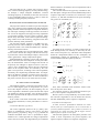
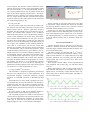
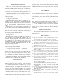
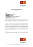
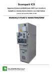
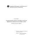
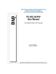
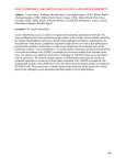
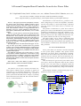
A Personal Computer Based Controller for an Active Power Filter M. J. Sepúlveda Freitas, João L. Afonso, Member, IEEE, Adriano Tavares, Júlio S. Martins, Member, IEEE DEI, University of Minho, Campus de Azurém, 4800-058 Guimarães, Portugal, e-mail : [email protected], [email protected], [email protected], [email protected] Abstract— This paper presents the development of controllers used in active power filters, applied to improve power quality in electrical systems. These active filters can be able to compensate for the following current or voltage related problems: short blackouts, current or voltage distortion due to harmonics, current or voltage unbalance in three-phase systems, flicker (subharmonics) and momentary over or under voltages. There are several causes for current and voltage distortion, namely, non linear loads, some types of voltage sources and thunderstorms. These problems cause instant and long term effects on the electrical equipment. The short term effects are imperfections, malfunctioning, interferences and degradation of the performance of devices or equipments. Effects in the long run are, basically, overheating and premature aging of the electric devices. The main goal of the work described in this paper is to develop an active power filter controller based on a personal computer and a standard multifunction data acquisition PCI bus card, due to its relative low cost, high processing capability, versatility and the numerous possibilities offered by such a computer-based system. Four different approaches were tested: using C++ on Microsoft Windows with the manufacturer’s device driver, using a new device driver for Windows, using Linux with real-time application interface; and using LabVIEW for Windows. Experimental and simulation results of the developed controllers are also presented. Index Terms—Active Power Filters, p-q Theory, Data Acquisition, Real-time Control, PC-Based Controller. I. INTRODUCTION The intensive use of power converters and other nonlinear loads in industry and by consumers in general are responsible for an increasing deterioration of the power systems voltage and current waveforms. Fig. 1 presents a power system with sinusoidal source voltage (vs) operating with a linear and a non-linear load. The non linear load current (iL1) contains harmonics. The harmonics in the line-current (is) produce a nonlinear voltage drop (∆v) in the line impedance, which distorts the load voltage (vL). Since load voltage is distorted, even the current at the linear load (iL1) becomes nonsinusoidal. The presence of harmonics in power lines results in greater power losses in the distribution system, interference problems in communication systems and, sometimes, in operation failures of electronic equipments, which are more and more sensitive since they include microelectronic control systems, which work with very low energy levels. The passive filters can be used to compensate some power quality problems, but they only solve the problems for the frequencies they were tuned for, their operation cannot be limited to a limited zone, and resonances cannot be fully prevented. II. ACTIVE POWER FILTERS Active power filters are electronic converters designed to solve power quality problems. They present several advantages over passive filters: compensation is dynamic, there is no risk of resonances, the power factor can be adjusted (for unit, for instance), they do not disturb the electrical network, and they can also compensate for phase unbalance. There are mainly two types of active power filters: shunt active filters, which are designed to filter the line currents and the series active filters (Fig. 2), designed to filter the line voltages. It is also possible to combine both topologies in order to provide simultaneously voltage and current filtering. The developed controllers presented in this paper are intended to be used in series active filters. ia a Power Source vsa b vsb c vca ib va vcb ic vcc vc N vsa vsb vsc vca* Controller ia ib ic vcb* Inverter vcc* Vdc + Series Active Filter Vdc Fig. 1 Power system with non-linear load Fig. 2 Series active power filter 0-7803-7912-8/03/$17.00 © 2003 IEEE Load vb The series filter acts as a voltage source inverter. In this case, constant switching frequency is easily obtained using, for example, a simple triangular modulation. Constant switching frequency is desirable, because the converter has a more predictable behaviour and it is easier to filter the resulting switching frequency harmonics. III. PC BASED ACTIVE POWER FILTER CONTROLLER The proposed controller is based on a personal computer (PC) with a general purpose multifunction data acquisition (DAQ) board for the PCI (Peripheral Component Interface) bus. The major advantages of this approach are: the relative low cost of the equipment; the high processing capabilities of a personal computer processor; and its versatility, which allows many other tasks, such as data acquisition and logging, remote access and monitoring, integration with other systems, and many other possibilities. The personal computer used has a 733 MHz Intel Pentium III processor and 512 Mbytes of memory. The data acquisition board is the model PCI-MIO-16E-4 manufactured by National Instruments. These cards usually have several analogue inputs, which can be used to measure the voltages and currents necessary to perform the control, and analogue outputs, which can be used to generate the voltage compensation signals. Although different operating systems and control algorithms were tested, the control sequence is always the same: first, the instantaneous values of voltages and currents are acquired by the analogue to digital converters (A/D converters) of the multifunction board; then the calculations based on the acquired values are executed by the computer’s microprocessor, according to the control algorithm; and finally, the compensating calculated values are outputted by the digital to analogue converters (D/A converters). The sequences of outputted values are then introduced in the power converter drive circuit of the series active filter. IV. THE CONTROL ALGORITHMS The methods applied to control the active filters are decisive in achieving the goals of compensation. In a power active filter digital controller, the data sampling rate, the control algorithms calculations speed and the data output rate should be as high as possible. Also, the delay between the data acquisition and the output activation should be as small as possible. If the control circuit deals with instant values and executes simple calculations, a better performance is easier to achieve. A. Controller Based on p-q Theory The control algorithm based on the p-q theory (also known as instantaneous reactive power theory for three phase systems), proposed by Akagi et al. [1], satisfies the conditions described above. Next is presented an implementation of a control algorithm for voltage compensation with a series active filter. This algorithm may be considered dual in relation to one used for current compensation with a shunt active filter [2]. The controller executes the p-q theory calculations: first, the three-phase voltages and currents (fundamental positive sequence components of currents) are converted to α−β−0 system (1, 2), and then instantaneous real power and imaginary power are calculated (3, 4). 1 2 1 2 1 2 v an 2 ⋅ 1 − 1 2 − 1 2 ⋅ vbn 3 0 3 2 − 3 2 v cn v0 vα = v β 1 2 1 2 1 2 ia 2 ⋅ 1 −1 2 − 1 2 ⋅ ib 3 0 3 2 − 3 2 ic i0 iα = iβ p= p+ ~ p = vα ⋅ iα + vβ ⋅ iβ ~ q = q + q = v ⋅i − v ⋅i α β β (1) (2) (3) (4) α According to the p-q theory, in order to achieve the desired filtering action, it is necessary to have only the constant value of real power (5), and all the other components should be compensated. Based on this assumption, the compensating voltages are calculated (6, 7), and finally, converted back to the three-phase system (8). ~ p = p− p vcα * = vcβ * = (5) 1 2 iα + iβ2 1 2 2 iα + iβ vca* v = cb* vcc* ( ) (6) ( ) (7) ⋅ iα ⋅ ~ p + iβ ⋅ q ⋅ iβ ⋅ ~ p − iα ⋅ q 1 2 ⋅ 1 3 1 2 2 2 1 0 vc 0* 3 2 ⋅ vcα * −1 2 − 1 2 − 3 2 vcβ * (8) Next, these calculated values should be used as references in the power active filter. For simplicity reasons, it was assumed no neutral is present, so, zero-sequence components are null. However, there is a major difficulty: the currents used in the controller’s algorithm are not the instant line currents, but their fundamental positive sequence components. B. Symmetrical Components In 1918, Fortescue presented his theorem: An unbalanced system of n related phasors can be resolved into n systems of balanced phasors. The n phasors of each set of components are equal in lengths, and the angles between adjacent phasors of the set are equal. This theorem applied to the three-phase particular case results in three components: the positive-sequence, the negative-sequence and the zero-sequence components. There are some ways to determine the fundamental positive sequence components of the line currents, but no one is simple. One possibility is to filter the line currents to obtain the fundamental currents and then apply the theorem. Other possibilities are the use of a PLL (Phase Locked Loop) [3] or a vector adaptative filter [4]. C. PI Control Algorithm The reference voltages for voltage compensation using the series active filter are always known. Exploring this fact, a completely different control algorithm is proposed. It is possible to generate the reference voltages synchronized with the mains voltages and use a proportional and integral control algorithm [5]. In this case, only the load voltages are acquired, because there is no need to measure line currents. The actual voltages are compared with the desired voltages (references) and voltage errors are generated. Then, the controller uses the symmetric values of the voltage errors as compensating voltages to be generated by the filter’s power converter. Fig. 3 Distorted mains voltages Fig. 4 Compensation voltages V. COMPUTER SIMULATIONS Some models were built with MatLab/Simulink to predict the results of the proposed control algorithms for the series active power filter. A. p-q Theory Simulations The model consists on a distorted mains three-phase system supplying a series active power filter with a linear three phase load. The active filter has a three-phase inverter with six IGBTs, and the medium point of the filter’s DC source is accessible. The mains three-phase voltage is distorted by the presence of 5th, 7th and 11th harmonics. The mains voltage is shown in Fig. 3. The compensating voltages calculated by the p-q theory algorithm are shown in Fig. 4. The active filter adds the compensating voltages to the mains voltages, causing the load voltages to become undistorted, like presented in Fig. 5. Fig. 5 Undistorted load voltages The line currents that were already filtered, now contain only the fundamental values. The model executes simple calculations, like sums and divisions by 3. The delays are very easy to implement in digitally sampled signals, just shifting the elements. Figs. 7 shows two periods of the line currents with a small unbalance, and the symmetrical components of line current ia. B. Model to Determine the SymmetricalCcomponents One possibility to determine the positive sequence components of the fundamental current is to filter the line currents, to obtain the fundamental values and then apply the Fortescue theorem. Another Simulink model was built to determine the symmetrical components, which are shown in Fig. 6. Fig. 6 Model to calculate symmetrical components Fig. 8 Mains voltage Fig. 9 Compensating voltage Fig. 10 Load voltage Fig. 7 Unbalanced line currents: (a) line currents waveforms; (b) line a zero-sequence component; (c) line a negative-sequence component; (d) positive-sequence component However, the Fortescue theorem is only valid on steady-state, therefore, the determination of symmetrical components is well suited just when changes in the power system rarely occur. Fig. 7 shows that this algorithm takes at least 2/3 of the period to provide the correct values. C. PI Controller A MatLab/Simulink model was built to analyze this alternative controller in a single phase series active filter (that can easily be transformed in a three-phase active filter). The mains voltage is distorted. In the instant 0.04 s, a perturbation occurs, to test the controller dynamics. The simulation provides promising results, as shown in Figs. 8 to 10. The most significant waveforms are presented: mains voltage (Fig. 8); the compensating voltage, which is symmetric to the voltage error (Fig. 9); and the load voltage (Fig. 10). VI. CONTROLLER IMPLEMENTATION A power active filter requires a fast controller, which does not miss samples, and where all real time deadlines must always be met. So, it needs hard real-time control. While today’s PC processors are fast enough for the computing tasks needed, the standard operating systems available are not optimized for this kind of application. Commercial acquisition boards also present some limitations, namely: analogue inputs are multiplexed and only one digital to analogue converter is used, causing the acquisition process to take a lot of time; very often only two analogue outputs are provided (which may imply the use of more than one board). But, once again, the main limitation has to do with software: board manufactures are not (yet) providing drivers allowing the use of the boards in a stimulus response basis, which is indispensable for fast real-time control applications. A. Using Microsoft Windows The data acquisition board used in this application includes a device driver for Microsoft Windows with a large set of functions to perform several tasks. A device driver is a software piece that interfaces with a particular piece of hardware. It translates the primitive, device dependent commands, to configure, read and write the electronics of the hardware interface into more abstract and generic function calls and data structure for the application programmer. Several test programs were built with Microsoft Visual C++ 6.0 to test the manufacturer’s device driver, but it always revealed poor performance: the acquisition times are very long, the set of functions available is not well suited for the application, and the controller program executes in low priority mode [6–8]. To meet all the timing constraints, an application’s tailored device driver for the acquisition board and Windows 2000 operating system is proposed. A WDM (Windows Driver Model) was designed to follow a synchronous I/O (Input/Output) model and offers instant value acquisition on each input channel, instead of buffered acquisitions of several samples. The Windows 2000 overhead was eliminated by moving the calculus of the compensating signals into the kernel mode, i.e., the designed WDM present a very special primitive that is able to perform all the three steps of the control sequence proposed above. The implementation of such a primitive was achieved, mainly due to the very simple calculus and short execution time required by the second step of the control sequence (the calculus of the compensating signal) [9–11]. B. Using Linux RT However, better results were achieved by another solution based on the same DAQ card using a real-time Linux kernel extension (RTAI – Realtime Application Interface) altogether with the Comedi (Control and Measurement Interface). The Comedi offers interface to lots of different DAQ cards and it consists of two complementary packages: comedi which implements the kernel space functionality and comedilib which implements the user space access to the device driver functionality. Comedi not only offers the primitives to access the functionality of the DAQ cards, but also to query the capabilities of the installed Comedi devices. That is, a user process can find out on-line what channels are available, and what their physical parameters are. Functionalities such as instruction (perform a single synchronous data acquisition on a given channel), scan (repeated instructions on a number of different channels, with a programmed sequence and timing) and command (process asynchronous data acquisition on a given set of channels) are offered altogether with a kernel space structures consisting of channel (represents the properties of one single channel), sub device (a set of functionally identical channels) and device (a set of sub devices physically implemented on the same interface card). The control program was written in C++ and compiled with gcc 2.95.3. C. Using LabVIEWTM for Windows The LabVIEW is a graphical programming environment that uses icons instead of text to create applications. In a conventional language, instructions determine program execution. In LabVIEW, execution is determined by data flow. LabVIEW allows to easily build a graphical user interface with the help of a set tools and objects. The interface is called front panel. The code consists in graphical representations of functions to control the front panel objects. The program itself is placed in the block diagram. It resembles a flowchart. It is also possible to add several software modules to LabVIEW in order to build specific applications [12]. The LabVIEW programs are called Virtual Instruments (VIs) because its appearance and operation mode are similar to physical measurement, calculation or control instruments. Fig. 11 shows the front panel (left) and the block diagram (right) of a VI to convert Celsius to Fahrenheit. Fig. 11 Example of a simple LabVIEW Virtual Instrument The PI controller for the single phase series active filter to compensate voltage distortion was built with LabVIEW for Microsoft Windows. There is also a real-time version of LabVIEW, but the standard version was used. In this case, only one DAQ card analogue input and one analogue output are used, diminishing the very long acquisition time and allowing the sample rate to be increased. The sampling frequency is constant, because it is possible to use the board’s internal clock to establish a fixed sampling rate. VII. CONTROLLER DELAY Another important factor in the series active filter performance is the delay between the data acquisition and the controller output. Another Simulink model was built to analyze controller delay effect. The mains voltages are distorted with 5th, 7th and 11th harmonics. The total harmonic distortion (THD) is 8.7%. Unlike current distortion, on voltage distortion, large high frequency transitions are not usually expected (however, voltage spikes may occur, but series active filters won’t compensate them). Some typical controller delays for this implementation were simulated: 100 µs delay (Fig. 12) and 300 µs delay (Fig. 13). With a delay inferior to 100 µs, output voltage is not too much affected, and distortion is acceptable. If the delay is higher (300 µs, for example), voltage distortion due to controller delay starts to become unacceptable, degrading series active filter action. Fig. 12 Effect of 100µs controller delay on output voltage Fig. 13 Effect of 300µs controller delay on output voltage VIII. EXPERIMENTAL RESULTS Like it was expected, the personal computer processor shows a very high calculation performance. The p-q theory algorithm calculations, with floating point and double precision take about 4 µs on a Pentium III @733MHz. There is no need of such a precision, so calculations can be even faster (and the used processor is already outdated). The Input/Output (I/O) system is slow (this was also expected). Results are somewhat different, depending on the operating systems. A. Using Microsoft Windows The manufacturer’s device driver revealed poor performance, so a new function driver was built according to the Windows Driver Model, based on an I/O control example [9], and performing control calculations on kernel mode. Unfortunately, it was not possible to successfully use this new driver, because the DAQ board manufacturer provided only incomplete and sometimes incorrect information about the board’s hardware. A debugger showed that the driver interface with the operating system worked fine, but the interface with the hardware did not. processor speed, and are usually designed only to do data acquisition for monitoring purposes or for process control. Hardware manufacturers do not provide yet low cost solutions to perform PC based hard real-time control. X. FUTURE WORK A shunt active power filter has already been developed in this department, controlled by an Intel 80296 microcontroller [13]. It will be easy to adapt the proposed personal computer based active filter controller to the shunt filter, using p-q theory algorithm to compensate current distortion. It is also possible to combine a shunt and a series active filter, being both controlled by the same PC, in order to implement an Unified Power Quality Conditioner (UPQC). It is also intended to develop a new PCI bus card with suitable specifications to perform these kind of tasks, together with a set of device drivers for Microsoft Windows and Linux. XI. ACKNOWLEDGEMENT The authors would like to thank Dr. Carlos Silva for his help in this work. B. Using Linux RT Real-time Linux proved to be efficient to execute the task. Sampling rate is constant and no data is lost. The maximum sampling frequency achieved was 14 kHz, but the computer freezes and sometimes even crashes. With 10 kHz sampling frequency, the computer has some margin to execute other tasks, and this frequency is still high enough to provide good results. The measured controller delay was 50 µs, a satisfactory result, according to the simulations. TM C. Using PI Controller LabVIEW XII. REFERENCES [1] [2] [3] [4] and Windows In this case, although it is not a real-time system, it’s possible to increase process priority in Windows task manager. Only one input and one output lines are used, allowing a 10 kHz fixed sampling frequency with no missing samples. The measured controller delay, including PI controller calculations was 70 µs, which is also satisfactory. [5] [6] [7] [8] IX. CONCLUSIONS Personal computers are relatively low cost pieces of hardware having very fast processors, capable to execute very complicated and extensive calculations in a very short period of time. However, they are not designed for hard real-time control tasks. The main problems are related to the operating systems that can only be circumvented by very skilled programmers. Another problem is the slow input/output system, requiring extra data acquisition boards. These boards are connected to the PCI bus and do not take advantage of the full [9] [10] [11] [12] [13] H. Akagi, Y. Kanazawa, A. Nabae, “Generalized Theory of the Instantaneous Reactive Power in Three-Phase Circuits”, IPEC'83 - Int. Power Electronics Conf., Tokyo, Japan, 1983, pp. 1375-1386 E. H. Watanabe, R. M. Stephan, M. Aredes, “New Concepts of Instantaneous Active and Reactive Power in Electrical Systems With Generic Loads”, IEEE Transactions on Power Delivery, Vol. 8, nº. 2, April 1993 T. Sezi, Ein Beitrag zur Wirk – und Blindleistungssteuerrung eines Zwischenkreisumritchers, Dr.-Ing Thesis, Technische Universitat Berlin, Germany, 1985, pp. 54-60 M. Esteve, Aplicación de Nuevas Técnicas de Control para el Desarrollo de Reguladores Activos de Potencia, Tesis Doctoral, Escuela superior de Ingenieros de la Universidad de Sevilla, Spain, April 2002, pp. 155-200 C. A. Quinn, Active Filtering of Harmonic Currents in Three-Phase Four-Wire Systems with Three-Phase and Single-Phase Non-Linear Loads, Doctoral Thesis, University of Minnesota, 1994 N. I. Corporation, DAQ DAQ-STCTM Technical Reference Manual System Timing Controller for Data Acquisition, January 1999 Edition, Part Number 340934B N. I. Corporation, DAQ NI-DAQTM User Manual for PC Compatibles Version 6.9.1, Data Acquisition Software for the PC, February 2001, Edition Part Number 321644K-01 N. I. Corporation, DAQ PCI E Series Register Level Programmer Manual Multifunction I/O Boards for PCI Bus, November 1999 Edition, Part Number 341079B-01 W. Oney, Programming the Microsoft Windows Driver Model, Microsoft Press, Bk&Cd-Rom edition 1999, ISBN 0-7356-0588-2 P. Viscarola, W. A. Mason, Windows NT Driver Development, New Riders Publishing; 1st edition, November 10, 1998, ISBN 1-5787-0058-2 C. Cant, Writing Windows WDM Device Drivers: Covers Nt 4, Win 98, and Win 2000, CMP Books; Bk&Cd Rom edition, July 1999, ISBN 0-8793-0565-7 N. I. Corporation, LabVIEWTM User Manual, July 2000 Edition, Pat Number 321353C-01 J. L. Afonso, H. R. Silva, J. S. Martins, “Active Filters for Power Quality Improvement”, IEEE Power Tech’2001, Porto, Portugal, 10-13 Set. 2001