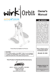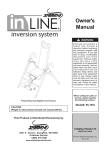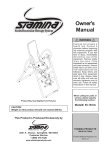
1
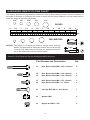
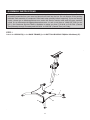
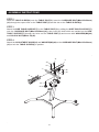
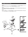
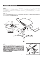
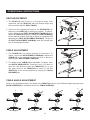
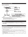
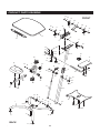
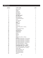
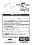
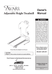
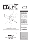
Owner's
Manual
TM
Product May Vary Slightly From Pictured.
When calling for parts or
service, please specify
the following number :
This Product is Distributed Exclusively by
Model#: 85-4000
STAMINA PRODUCTS
2040 N. Alliance, Springfield, MO 65803
Customer Service
1 (800) 375-7520
www.staminaproducts.com
MADE IN CHINA
© 2014 Stamina Products, Inc.
2014, 11
Call Us First
Customer Service
1 (800) 375-7520
www.staminaproducts.com
THANK YOU FOR PURCHASING THE
WirkTM Linea Standup Workstation
To enact your warranty, please register your product
by going to register.staminaproducts.com
To help you get started, we have pre-assembled most of your
WirkTM Linea Standup Workstation at the factory with the exception
of those few parts left unassembled for shipping purposes.
Simply follow the few assembly instructions set forth in this manual.
Should you have any questions,
please call our Customer Service Department toll-free number,
1 (800) 375-7520
Monday - Thursday, 7:30 A.M. - 5:00 P.M., Central Time.
Friday, 8:00 A.M. - 3:00 P.M., Central Time.
ONLINE
CUSTOMER SERVICE
[email protected]
www.staminaproducts.com
TELEPHONE
FAX
CUSTOMER SERVICE
Tel: 1 (800) 375-7520
CUSTOMER SERVICE
Fax: (417) 889-8064
MAIL
STAMINA PRODUCTS, INC.
ATTN: Customer Service
P.O. Box 1071
Springfield, MO. 65801-1071
TABLE OF CONTENTS
Hardware Identification Chart .................... 3
Assembly Instructions ................................ 4
Operational Instructions ............................. 9
Storage ....................................................... 10
Maintenance ...............................................10
Warranty ..................................................... 11
Product Parts Drawing ..............................12
Parts List .................................................... 13
WirkTM Coaster Toss Rules ....................... 14
Fax/Mail Ordering Form ............................ 15
2
HARDWARE IDENTIFICATION CHART
This chart is provided to help identify the fasteners used in the assembly process. Place the washers or
the ends of the bolts or screws on the circles to check for the correct diameter. Use the small scale to
check the length of the bolts and screws.
3/16"
1/4"
5/16"
3/8"
1/2"
INCHES
0
0
1/2
10
1
20
1/2
30
40
2
50
1/2
60
3
70
1/2
80
4
1/2
5
1/2
90 100 110 120 130 140 150
MILLIMETERS
6
8
10
6
in.
mm.
length
12
NOTICE: The length of all bolts and screws, except those with flat
heads, is measured from below the head to the end of the bolt
or screw. Flat head bolts and screws are measured from the
top of the head to the end of the bolt or screw.
length
After unpacking the unit, open the hardware bag and make sure that you have all the following
fasteners. Some fasteners may be already attached to the parts.
Part Number and Description
Qty
33
Bolt, Button Head (M8 x 1.25 x 110mm)
2
34
35
Bolt, Button Head (M8 x 1.25 x 60mm)
Bolt, Button Head (M8 x 1.25 x 50mm)
1
2
37
40
Bolt, Button Head (M8 x 1.25 x 20mm)
Bolt, Button Head (M6 x 1 x 15mm)
3
8
41
Carriage Bolt (M8 x 1.25 x 50mm)
1
44
Washer (M8)
6
45
Nylock Nut (M8 x 1.25)
5
3
ASSEMBLY INSTRUCTIONS
Place all parts from the box in a cleared area and position them on the floor in front of you. Remove
all packing materials from your area and place them back into the box. Do not dispose of the packing
materials until assembly is completed. Read each step carefully before beginning. If you are missing
a part, please go to staminaproducts.com under the Service section and order the part needed,
e-mail us at [email protected], or call us toll free at 1-800-375-7520 (in the
U.S.). Our Customer Service Staff is available to assist you from 7:30 A.M. to 5:00 P.M. (Central
Time) Monday through Thursday and 8:00 A.M. to 3:00 P.M. (Central Time) on Friday.
STEP 1
Attach the UPRIGHT(2) to the BASE FRAME(1) with BUTTON HEAD BOLTS(M8x1.25x20mm)(37).
2
37
16
37
4
1
ASSEMBLY INSTRUCTIONS
STEP 2
Slide the TABLE SLIDER(6) onto the TABLE POST(3). Insert the CARRIAGE BOLT(M8x1.25x50mm)
(41) through the square hole on the TABLE POST(3) and the slot on the TABLE SLIDER(6).
STEP 3
Attach the SIDE TABLE SUPPORT(7) to the TABLE POST(3) by sliding the SIDE TABLE SUPPORT(7)
onto the CARRIAGE BOLT(M8x1.25x50mm)(41), then insert the bolts which are welded on the SIDE
TABLE SUPPORT(7) through the holes on the TABLE POST(3) and secure with WASHERS(M8)(44)
and NYLOCK NUTS(M8x1.25)(45).
STEP 4
Attach the ADJUSTMENT KNOB(24) and WASHER(M8)(44) to the CARRIAGE BOLT(M8x1.25x50mm)
(41) to lock the TABLE SLIDER(6) in position.
41
3
45
44
7
45
44
6
44
24
5
ASSEMBLY INSTRUCTIONS
STEP 5
Refer illustrations A, B, and C. Place the BACK SUPPORT(9) into the TABLE SLIDER(6) and turn it as
shown in the below illustrations to install the BACK SUPPORT(9) into position.
STEP 6
Attach the SEAT SUPPORT(5) to the SEAT SLIDER(4) with BUTTON HEAD BOLT(M8x1.25x60mm)(34),
WASHER(M8)(44), and NYLOCK NUT(M8x1.25)(45).
STEP 7
Attach the SEAT(18) to the SEAT SUPPORT(5) with BUTTON HEAD BOLTS(M8x1.25x50mm)(35).
Insert the PULL PIN(29) into the SEAT SLIDER(4) for storage.
9
A.
9
6
6
18
3
45
44
4
9
B.
6
34
5
29
35
6
C.
9
6
ASSEMBLY INSTRUCTIONS
STEP 8
Refer to the illustration below. Attach the MOUNTING BRACKETS(10) and TALL MOUNTING
BRACKETS(11) to the bottom side of the TABLE(15) with BUTTON HEAD BOLTS(M6x1x15mm)(40).
40
40
40
10
10
15
40
11
11
BOTTOM VIEW
15
7
ASSEMBLY INSTRUCTIONS
STEP 9
Refer to the Bottom View below. Attach the TABLE(15) to the unit by attaching the TALL MOUNTING
BRACKETS(11) to the TABLE SLIDER(6) and attaching the MOUNTING BRACKETS(10) to the BACK
SUPPORT(9) with BUTTON HEAD BOLTS(M8x1.25x110mm)(33), WASHERS(M8)(44), and NYLOCK
NUTS(M8x1.25)(45).
STEP 10
Attach the SIDE TABLE(17) by inserting the SIDE TABLE POST(8) into the SIDE TABLE SUPPORT(7)
and secure with the LOCKING KNOB(23).
45
15
44
45
44
7
11
6
9
33
17
33
10
15
8
23
BOTTOM VIEW
NOTE:
You can attach the SIDE TABLE(17) to the left side. Remove
the BUTTON HEAD BOLTS(M6x1x30mm)(39) from the SIDE
TABLE POST(8) to disassemble the SIDE TABLE(17). Turn
the SIDE TABLE POST(8) to the left side and attach the SIDE
TABLE(17) back to the SIDE TABLE POST(8) with BUTTON
HEAD BOLTS(M6x1x30mm)(39). Inserting the SIDE TABLE
POST(8) into the SIDE TABLE SUPPORT(7) and secure with
the LOCKING KNOB(23).
8
15
17
7
8
39
23
OPERATIONAL INSTRUCTIONS
SEAT ADJUSTMENT
1.The SEAT(18) can be set to a 30 degree angle from
horizontal. Set the SEAT(18) with the desired angle and
lock in position with the PULL PIN(29).
18
4
2.There are four adjustment holes on the UPRIGHT(2) for
adjusting the SEAT(18) to different heights. To adjust,
loosen and pull the SEAT ADJUSTMENT KNOB(22), then
adjust the SEAT(18) height by sliding the SEAT SLIDER(4)
to the desired position and lock in place by releasing and
tightening the SEAT ADJUSTMENT KNOB(22). The pin of
the SEAT ADJUSTMENT KNOB(22) must be inserted into
one of the adjustment holes.
22
5
2
29
15
TABLE ADJUSTMENT
12
1.The TABLE(15) can adjust forward or backward. To
adjust, loosen the ADJUSTMENT KNOB(24). Adjust the
TABLE(15) to the desired position and lock in place by
tightening the ADJUSTMENT KNOB(24).
13
24
2
2. The height of the TABLE(15) is adjustable. To adjust, open
the QUICK RELEASE(13). Push the Lever (12) down to
allow the Gas Shock to raise the TABLE(15) up, or you
can push down on the TABLE(15) to lower it. Lock the
TABLE(15) at the desired position by closing the QUICK
RELEASE(13).
TABLE ANGLE ADJUSTMENT
Refer to the illustrations below. The angle of the TABLE(15) can be set to different angles by placing the
BACK SUPPORT(9) to a different slot on the TABLE SLIDER(6).
9
Zero Degree
9
9
9
6
15
15
15
15
6
6
15 Degree
30 Degree
9
45 Degree
6
OPERATIONAL INSTRUCTIONS
WEIGHT LIMITATIONS
WARNING:Serious injuries can occur from furniture tip-over. To help prevent tip-over:
Do not exceed listed weight limits
Never allow children to climb or hang on the furniture
Do not lean on the desktop in any direction
STORAGE
1. To store the WirkTM Linea Standup Workstation, simply keep it in a clean dry place.
2. To move the WirkTM Linea Standup Workstation, lift the SEAT(18) and use the WHEELS(30) on the
BASE FRAME(1).
MAINTENANCE
The safety and integrity designed into the WirkTM Linea Standup Workstation can only be maintained
when the WirkTM Linea Standup Workstation is regularly examined for damage and wear. Special
attention should be given to the following:
1. Verify that all nuts and bolts are present and properly tightened. Replace missing nuts and bolts.
Tighten loose nuts and bolts.
2. It is the sole responsibility of the user/owner to ensure that regular maintenance is performed.
3. Worn or damaged components shall be replaced immediately or the Wirk TM Linea Standup
Workstation removed from service until repair is made.
4. Only Stamina Products supplied components shall be used to maintain/repair the WirkTM Linea
Standup Workstation.
5. Keep your WirkTM Linea Standup Workstation clean by wiping it off with an absorbent cloth after
use.
10
LIMITED WARRANTY
MODEL 85-4000
WARRANTY
Stamina Products, Inc. warrants that this product will be free from defects in materials and workmanship
under normal use, service, proper assembly and proper operation for a period of 90 days on the
parts and three years on the frame from the date of the original purchase from an authorized retailer.
THIS WARRANTY SHALL NOT APPLY TO ANY PRODUCT WHICH HAS BEEN SUBJECT
TO COMMERCIAL USE, ABUSE, MISUSE, ALTERATION OF ANY TYPE OR CAUSE OR TO
ANY DEFECT OR DAMAGE CAUSED BY IMPROPER ASSEMBLY, REPAIR, REPLACEMENT,
SUBSTITUTION OR USE WITH PARTS OTHER THAN PARTS PROVIDED BY STAMINA PRODUCTS,
INC. Commercial use includes use of the product in athletic clubs, health clubs, spas, gymnasiums,
exercise facilities, and other public or semipublic facilities whether or not the product's use is in
furtherance of a profit making enterprise, and all other use which is not for personal, family, or household
purposes.
To implement this limited warranty, send a written notice stating your name, date, and place of purchase
and a brief description of the defect along with your receipt to Stamina Products, Inc. P.O. Box 1071,
Springfield Missouri, USA, 65801-1071, or email us at [email protected], or
call us at 1-800-375-7520. If the defect is covered under this limited warranty, you will be requested to
return the product or part to us for free repair or replacement at our option. NO ACTION FOR BREACH
OF THIS LIMITED WARRANTY MAY BE COMMENCED MORE THAN ONE (1) YEAR AFTER THE
DATE THE ALLEGED BREACH WAS OR SHOULD HAVE BEEN DISCOVERED. NO ACTION FOR
BREACH OF ANY IMPLIED WARRANTY MAY BE COMMENCED MORE THAN ONE (1) YEAR AFTER
DELIVERY OF THE PRODUCT TO THE PURCHASER. This limited warranty is not transferable. IF
ANY PART OF THE PRODUCT IS NOT IN COMPLIANCE WITH THIS LIMITED WARRANTY OR ANY
IMPLIED WARRANTY, THE REMEDY OF REPAIR OR REPLACEMENT IS THE EXCLUSIVE REMEDY
AVAILABLE TO YOU. In the event that the purchaser makes any claim under this limited warranty or any
implied warranty, the Warrantor reserves the right to require the product to be returned for inspection,
at the purchaser's expense, to the Warrantor's premises in Springfield, Missouri. Return of the enclosed
warranty registration card is not required for warranty coverage, but is merely a way of establishing the
date and place of purchase.
Stamina Products, Inc. SHALL NOT BE LIABLE FOR THE LOSS OF USE OF ANY PRODUCT, LOSS
OF TIME, INCONVENIENCE, COMMERCIAL LOSS OR ANY OTHER INDIRECT, CONSEQUENTIAL,
SPECIAL OR INCIDENTAL DAMAGES DUE TO BREACH OF THE ABOVE WARRANTY OR ANY
IMPLIED WARRANTY.
This limited warranty is the only written or express warranty given by Stamina Products, Inc. This
warranty gives you specific legal rights, and you may also have other legal rights which vary from state
to state. ANY OTHER RIGHT WHICH YOU MAY HAVE, INCLUDING ANY IMPLIED WARRANTY OR
MERCHANTABILITY OR FITNESS FOR A PARTICULAR PURPOSE, IS LIMITED IN DURATION TO
THE DURATION OF THIS WARRANTY.
The laws in some jurisdictions restrict the rights of manufacturers and distributors of consumer goods
to disclaim or limit implied warranties and consequential and incidental damages with respect thereto.
If any such law is found to be applicable, the foregoing disclaimers and limitations of and on implied
warranties and consequential and incidental damages with respect thereto shall be disregarded and shall
be deemed not to have been made to the extent necessary to comply with such legal restriction.
11
PRODUCT PARTS DRAWING
45
44
FRONT
10
28
9
28
45
41
11
44
10
40
33
28
40
15
40
19
28
11
6
33
45
40
44
45
44
26
32
3
7
17
44
24
18
45
44
22
4
23
12
45
34
27
36
44
25
43
39
42
13
29
5
20
8
45
26
14
31
2
35
44
30
44
45
44
1
21
16
30
42
44
37
38
38
21
BACK
37
21
21
12
PARTS LIST
PART#
1
2
3
4
5
6
7
8
9
10
11
12
13
14
15
16
17
18
19
20
21
22
23
24
25
26
27
28
29
30
31
32
33
34
35
36
37
38
39
40
41
42
43
44
45
46
47
48
49
PART NAME
Base Frame
Upright
Table Post
Seat Slider
Seat Support
Table Slider
Side Table Support
Side Table Post
Back Support
Mounting Bracket
Tall Mounting Bracket
Lever
Quick Release
Gas Shock
Table
Base Board
Side Table
Seat
Pencil Tray
Square Plug (20mm x 20mm)
Feet
Seat Adjustment Knob
Locking Knob
Adjustment Knob
Support Plate
Oval Bushing
Sleeve
Bushing
Pull Pin
Wheel
Square Plug (38mm x 38mm)
Coaster
Bolt, Button Head (M8 x 1.25 x 110mm)
Bolt, Button Head (M8 x 1.25 x 60mm)
Bolt, Button Head (M8 x 1.25 x 50mm)
Bolt, Button Head (M8 x 1.25 x 40mm)
Bolt, Button Head (M8 x 1.25 x 20mm)
Bolt, Flat Head (M6 x 1 x 45mm)
Bolt, Button Head (M6 x 1 x 30mm)
Bolt, Button Head (M6 x 1 x 15mm)
Carriage Bolt (M8 x 1.25 x 50mm)
Bolt, Socket Head (M8 x 1.25 x 25mm)
Screw, Flat Head (M4 x 0.6 x 30mm)
Washer (M8)
Nylock Nut (M8 x 1.25)
Allen Wrench (5mm)
Allen Wrench (6mm)
Combination Wrench
Manual
13
QTY
1
1
1
1
1
1
1
1
1
2
2
1
1
1
1
1
1
1
1
1
4
1
1
1
1
2
1
4
1
2
1
1
2
1
2
1
3
4
2
8
1
2
1
11
9
1
1
1
1
14
TO CONTACT CUSTOMER SERVICE
For your convenience, Stamina’s customer service representatives can be reached by email at
customerservice@ staminaproducts.com or by phone at 1-800-375-7520 (in the U.S.). Our customer
service representatives are available Monday through Thursday from 7:30 a.m. until 5:00 p.m., and
Friday 8:00 a.m. until 3 p.m. Central Time.
ONLINE
CUSTOMER SERVICE
[email protected]
www.staminaproducts.com
TELEPHONE
CUSTOMER SERVICE
Tel: 1 (800) 375-7520
FAX
MAIL
CUSTOMER SERVICE
Fax: (417) 889-8064
STAMINA PRODUCTS, INC.
ATTN: Customer Service
P.O. Box 1071
Springfield, MO. 65801-1071
Would you like to recieve email information or special offers from Stamina Products? Register at contact
staminaproducts.com.
TO ORDER PARTS
If there are missing or damaged parts, you can go to parts.staminaproducts.com and order those parts. If
you have questions, please contact customer service. Do not return the product. To order parts by mail,
fill out the sheet below and fax it to 417-889-8064. The part will be mailed to your address.
Detach and Mail or Fax the Form Below
PARTS ORDER FORM
Stamina Products, Inc.
P.O. Box 1071
Springfield, MO 65801-1071
Mr./Ms: ......................................................................................................................................................................................
Address: ..........................................................................................................................
Apt. #: ........................................
City: .........................................................
Zip Code: ...................................
State: .......................................................
IMPORTANT : We must have your phone number to process the order!
Phone #: (
) ...................................................................... Work Phone #: (
) ...................................................
Date of Purchase: ........................................................................
Model #: ....................................................................................................................................................................................
Purchased From: .......................................................................................................................................................................
IMPORTANT : Before filling out the form below make sure you have the correct information.
Refer to the parts list to make sure you're ordering the right parts!
PART #
EXAMPLE:
1
DESCRIPTION
Rear Stabilizer
QUANTITY
1