1
R1L-E2A
INTRINSICALLY SAFE
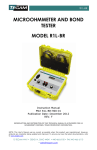
MICROOHMMETER
MODEL R1L-E2A
Instruction Manual
PN# R1L-E2A-900-01
Publication Date: July 2013
REV. F
This document may not be modified without the approval of the Notified Body.
10 TEGAM WAY • GENEVA, OHIO 44041 • 440-466-6100 • FAX 440-466-6110 • [email protected]
R1L-E2A
0539
II 1 G
Ex ia IIA T4 Ga
-20C ≤ Ta ≤ +50C
DEMKO 11 ATEX 1048757X
IECEx UL 11.0006X
Control Drawing 13742
Ground Indicator For Use in Hazardous Locations
Class I Zone 0, Group IIA
Class I Division 1, Group D
4EV4
SAFETY WARNINGS
This unit is intrinsically safe. WARNING: Substitution of components may impair
intrinsic safety. See accompanying instruction manual for operating and
maintenance instructions.
WARNING: Batteries are part of the intrinsically safe system. Use only the
specific battery type and manufacturers listed in the user manual. Use of other
batteries could impair intrinsic safety. Do not mix batteries of different
manufactures. Do not mix fresh batteries with old batteries.
WARNING: To reduce the risk of ignition of a flammable or explosive
atmosphere, batteries must be changed only in a location known to be nonhazardous.
WARNING: When operated in a potentially explosive atmosphere, this unit may
not be used if capacitance, inductance or other circuitry is connected to the
bond or structure under test.
WARNING: To prevent ignition of flammable or combustible atmospheres, read,
understand and adhere to manufacturer’s live maintenance procedures.
WARNING: Panel Bezel is a Light Metal alloy. Avoid risk of ignition caused by
impact or friction sparks resulting from impact to or friction with the panel bezel
by protecting the panel and bezel from impact and friction.
AVERTISSEMENTS DE SURETE
Cette unité est intrinsèquement sûre. AVERTISSEMENT: la substitution des
composants peut altérer la sûreté intrinsèque. Voyez le manuel d'instruction
pour des instructions d'opération et d'entretien.
AVERTISSEMENT: Les piles font partie du système d'une sécurité inhérente.
Employez seulement le type et les fabricants spécifiques de piles énumérés
dans le manuel d'utilisation. L'utilisation d'autres piles a pu altérer la sûreté
intrinsèque. Ne mélangez pas les types de pile. Ne pas mélanger des piles
neuves avec des piles usagées
10 TEGAM WAY • GENEVA, OHIO 44041 • 440-466-6100 • FAX 440-466-6110 • [email protected]
R1L-E2A
AVERTISSEMENT: Pour réduire le risque d'allumage d'une atmosphère
inflammable ou explosive, les piles doivent être changées seulement dans une
zone connue pour être non-dangereuse.
AVERTISSEMENT: Quand opérée dans une atmosphère potentiellement
explosive, cette unité ne peut pas être utilisée si la capacitance, l’inductance ou
les autres circuits sont connectés au lien ou à la structure sous l’essai.
AVERTISSEMENT: Pour empêcher l'allumage des atmosphères inflammables ou
combustibles, lisez, comprenez et adhérez aux procédures d'entretien sous
tension.
AVERTISSEMENT : La monture de panneau est un alliage léger en métal. Évitez
le risque d'allumage provoqué par des étincelles d'impact ou de frottement en
résultant de l'impact à ou du frottement avec la monture de panneau en
protégeant le panneau et la monture contre l'impact et le frottement.
10 TEGAM WAY • GENEVA, OHIO 44041 • 440-466-6100 • FAX 440-466-6110 • [email protected]
TABLE OF CONTENTS
TABLE OF CONTENTS
1. INSTRUMENT DESCRIPTION
Introduction ......................................................... 1-1
Performance Characteristics ................................... 1-1
Table 1: Specifications ....................................... 1-1
Description of Equipment ....................................... 1-2
Figure 1: Front Panel and Controls....................... 1-5
List of Items Furnished .......................................... 1-6
Storage and Shipping Requirements ........................ 1-6
2. PREPARATION FOR USE AND INSTALLATION
Unpacking and Inspection ...................................... 2-1
Preparation for Use................................................ 2-2
Figure 2a: HTP-101A Probe Connections ............... 2-3
Figure 2b: SKP-8 Probe Connections .................... 2-3
3. OPERATING INSTRUCTIONS ................................. 3-1
4. SERVICE INFORMATION
Preparation for Repair or Calibration Service ............. 4-1
Expedite Repair and Calibration Form ...................... 4-2
Warranty.............................................................. 4-3
10 TEGAM WAY • GENEVA, OHIO 44041 • 440-466-6100 • FAX 440-466-6110 • [email protected]
INSTRUMENT DESCRIPTION
SECTION 1
INSTRUMENT DESCRIPTION
1.1 Introduction
The TEGAM Model R1L-E2A is an intrinsically safe portable
bond meter/microohmmeter designed to measure low
values of resistance, from 1 µΩ to 20 Ω. A four point
measurement method is utilized in order to eliminate any
errors caused by the resistance of the measuring leads. Two
leads are used to pass a constant regulated current through
the resistance under test, and two leads are used to
measure the resulting voltage drop across the resistance
under test. The R1L-E2A then uses Ohm’s law to calculate
the resistance and displays the value digitally on a liquid
crystal display (LCD). The R1L-E2A cycles the current ON
and OFF during the measurement. During the OFF state,
thermal and offset voltages, occurring in the voltage
measurement chain, are stored, and then used as a
correction during the ON current time.
The current used for the measurement is well regulated to
be constant over large changes in the unknown resistance
and/or the resistance of the test leads. If the resistance
under test becomes too high on a given range, the display
shows a “1” followed by three blanks.
1.2 Performance Characteristics
The R1L-E2A has five resistance ranges, with test current,
resolution, and scale as shown below in Table 1.
Range
1
2
3
4
5
Full Scale
(Ω)
1.999 m
19.99 m
199.9 m
1.999
19.99
Resolution
(Ω)
1µ
10 µ
100 µ
1m
10 m
Test Current
Peak (A)
1.3
130 m
13 m
1.3 m
0.13 m
Table 1: Range Specifications
Page 1-1
10 TEGAM WAY • GENEVA, OHIO 44041 • 440-466-6100 • FAX 440-466-6110 • [email protected]
INSTRUMENT DESCRIPTION
Accuracy: All ranges: 0.1% of reading ± 2 counts.
Accuracy may become degraded in the presence of
significant levels of RF field. At a RF field strength of 3 V/m,
accuracy is 1% of reading ± 2 counts for the four lowest
ranges (1.999 mΩ full scale through 1.999 Ω full scale) and
2% of reading ± 2 counts on the 19.99 Ω full scale range.
Operating Temperature: -20 °C to +50 °C.
Relative humidity: 0 to 90%, non-condensing.
1.3 Description of Equipment
A rugged heavy-duty static-dissipative ABS/Polycarbonate
plastic case is supplied to contain and protect the R1L-E2A.
When closed, a gasket seals the lid to keep out water and
dirt, while the R1L-E2A is transported through rain or other
environmentally hostile conditions. When the lid is open, a
second gasket provides additional, although reduced
protection, for the front panel. The removable battery access
cover also has a gasket. The front panel is aluminum with
durable polycarbonate graphical overlay. The lid of the R1LE2A case further serves as a storage area for the supplied
pair of test probes and instruction manual.
Dimensions of the case are 17” W x 11.5” D x 7.1” H.
Weight is 18 pounds (including test probes, power cord,
battery cells, and manual).
With the lid open for operation, the front panel and its
controls are readily accessible. Controls and connectors may
be operated while wearing safety gloves.
Electrical: Power is from three alkaline D-cells. Current
drain depends on the measurement range selected, and
battery capacity. Based on an average drain of 150 mA, and
brand new D cells and a 25 °C ambient, the battery cells will
typically give up to 80 hours of operation (with the backlight
OFF). Increasing battery drain and decreasing temperature
both result in decreased battery capacity. Extended use on
the 2 mΩ range or with backlight on will reduce operating
Page 1-2
10 TEGAM WAY • GENEVA, OHIO 44041 • 440-466-6100 • FAX 440-466-6110 • [email protected]
INSTRUMENT DESCRIPTION
time dramatically. At low ambient in the 2 mΩ range, battery
life will be approximately three hours of continuous
measurement for new cells. Continuous measurement is very
unlikely, and high current is only drawn when test probes are
connected and touching a low-resistance surface. It is
expected that in most foreseeable conditions, one set of
batteries will allow at least eight hours of normal intermittent
testing activity.
CAUTION
THIS INSTRUMENT IS TO BE OPERATED FROM BATTERY
POWER ONLY. CONNECTION OF AN EXTERNAL SUPPLY WILL
RESULT IN A HAZARDOUS CONDITION AND MAY DAMAGE
THE R1L-E2A
Front Panel Controls and Displays (Refer to figure 1)
POWER ON/OFF pushbutton switch turns battery power ON
and OFF for the R1L-E2A. It is protected by a ring to make
accidental actuation more difficult.
The RANGE switch is used to select the desired resistance
range for the resistance under test. There are five ranges
marked 2 mΩ, 20 mΩ, 200 mΩ, 2 Ω, and 20 Ω. Note that
although the ranges are marked “2" etc., the actual reading
limit is 1.999 mΩ, etc. Resistance readings on any range
exceeding 1999 (with appropriate decimal point) show as an
“over-range” condition, indicated by a display of “1” followed
by three blanks.
BACKLIGHT pushbutton is a momentary pushbutton switch
which controls PC board circuitry to cycle through three
states for the backlight. The default state is OFF, which
occurs each time the R1L-E2A is powered up, regardless of
previous history, and is indicated by the full black circle.
Depressing the pushbutton once causes the backlight to
cycle to its half-bright state indicated by the half-lighted
circle. Depressing the switch a second time causes the
backlight to cycle to its full-bright state, indicated by the
non-filled circle. A third depression of the backlight switch
will cycle the backlight to OFF.
Page 1-3
10 TEGAM WAY • GENEVA, OHIO 44041 • 440-466-6100 • FAX 440-466-6110 • [email protected]
INSTRUMENT DESCRIPTION
DISPLAY is a 3½ digit LCD with decimal points, reading from
0.001 mΩ to 19.99 Ω full scale.
LOW BATTERY is indicated by “LOBAT” on the display, in
addition to the resistance reading.
Four binding posts are provided for the connection of test
probes. (Only HTP-101A or SKP-8 test probes may be used
in an explosive atmosphere). The two binding posts labeled
+I and -I supply a constant current to the resistance under
test. The binding posts labeled +E and -E sense the voltage
developed across the resistance under test. The binding
posts are color coded to match the colors of the spade lug
insulations on the supplied test probes.
Test Probes
The Model R1L-E2A unit is shipped with one or both of the
test probes: a pair of pistol-shaped test probes (HTP-101A)
and/or a pair of Kelvin Probes (SKP-8). The probes are color
coded; a red one for use with the left hand, and a white one
for use with the right hand. Each probe is attached to an eight
foot length of cable comprised of two 12 AWG insulated wires
for the HTP-101A and 18 AWG insulated wires for the SKP-8.
The ends of the probe cables terminate in spade lugs, which
have color coded insulation corresponding to the colors of the
front panel binding posts. The cable strain relief has a band
with appropriate left or right identification.
Each test probe has two sharply-pointed spring-loaded
conductors extending from the nose. One conductor of each
probe is for current, and the other is for voltage.
When firmly pressed against a surface, the pointed
conductors of the HTP-101A retract with a rotating motion,
to help cut through non-conductive surface films. When not
in use, the probes are meant to be stored in the lid of the
R1L-E2A case.
Page 1-4
10 TEGAM WAY • GENEVA, OHIO 44041 • 440-466-6100 • FAX 440-466-6110 • [email protected]
INSTRUMENT DESCRIPTION
Figure 1: Front Panel and Controls
Page 1-5
10 TEGAM WAY • GENEVA, OHIO 44041 • 440-466-6100 • FAX 440-466-6110 • [email protected]
INSTRUMENT DESCRIPTION
1.4 List of Items Furnished
1 each Model R1L-E2A Microohmmeter.
1 each Power Cord.
1 set of Alkaline Battery Cells Approved for R1L-E2A.
1 each Instruction Manual.
Depending on the configuration ordered:
1 set of Pistol-shaped Test Probes (HTP-101A) and/or
1 set of Kelvin Probes (SKP-8).
1.5 Storage and Shipping Requirements
Storage Temperature: -40 °C to +71 °C.
Relative humidity: 0 to 100%, non-condensing.
The Model R1L-E2A is a rugged instrument and requires
no special covering, preservation, or special cradles.
During shipment, packaging must provide sufficient
resilient material in accordance with standard packaging
practices to prevent excessive shock to the power supply
and display.
Page 1-6
10 TEGAM WAY • GENEVA, OHIO 44041 • 440-466-6100 • FAX 440-466-6110 • [email protected]
PREPARATION FOR USE AND INSTALLATION
SECTION 2
PREPARATION FOR USE AND INSTALLATION
2.1 Unpacking and Inspection
Upon receipt, the R1L-E2A and its accessory kit should be
carefully unpacked and removed from the shipping
container. Separate the units from the packing material and
inspect the instrument for any external damage.
• If any dents, broken, or loose parts are seen, do not use
the equipment. Notify TEGAM immediately.
• Note that the instrument is shipped with its batteries
removed. Unwrap the three D-cells which were shipped
with the unit.
Release the two latches which secure the lid of the Model
R1L-E2A Microohmmeter, and open the lid. Since the lid is
well gasketed, it may be difficult to open if there is an
appreciable difference between external and internal air
pressure. Check for the presence of two test probes stored in
the cavity in the lid. If the test probes or instruction manual
are not present, and the instrument is new, report this
immediately to TEGAM.
2.2 Preparation for Use
WARNING
DO NOT INSTALL, CHANGE, OR REMOVE THE R1L-E2A
BATTERY CELLS IN AN EXPLOSIVE ATMOSPHERE! A
SPARK MIGHT BE GENERATED, WHICH COULD RESULT IN
AN EXPLOSION.
WARNING
BATTERIES ARE PART OF THE INTRINSICALLY SAFE
SYSTEM. USE ONLY RECOMMENDED BATTERIES. DO NOT
MIX BATTERIES. USE OF ANY OTHER BATTERY OR MIXED
BATTERIES MAY RESULT IN A HAZARDOUS CONDITION.
Page 2-1
10 TEGAM WAY • GENEVA, OHIO 44041 • 440-466-6100 • FAX 440-466-6110 • [email protected]
PREPARATION FOR USE AND INSTALLATION
Note that the Model R1L-E2A is shipped with its battery cells
removed. Three battery cells are shipped with each new unit.
• Loosen the six captive screws around the outside edge of
the battery access panel using a Phillips No. 2 screwdriver,
and remove the panel.
• Check for correct polarity and install the three D-cells in
the battery holder. When installing the cells, rotate them
slightly to ensure connection to the battery holder
contacts. The cells are connected in series for a nominal
voltage of 4.5 V.
• Use only Alkaline or Manganese D Cells that have been
proven by a Nationally Recognized Testing Laboratory to
meet the requirements of UL60079-11, section 10.5.2.
Use of any other battery will invalidate the Type certificate
and will create a hazardous condition. The only batteries
that TEGAM has secured such testing on, and which are
approved for use in the R1L-E2A are listed on the Type
Certificate and are:
o Energizer E95
• Reinstall the battery access panel and tighten the six
captive screws to secure it.
If the test probes are to be used, connect their leads to the
corresponding color-coded binding post on the R1L-E2A front
panel, as shown in figure 2a and 2b. Only HTP-101A or SKP-8
test probes or leads may be used in an explosive atmosphere.
Ensure they are properly connected for a four-wire
measurement. For example, if measuring the value of a low
value resistor, connect the +I and –I current leads to the
ends of the resistor leads away from the resistor body.
Connect the +E and –E leads between the current leads and
the resistor body at the points between which the resistance
value is to be determined, making sure the +E lead is on the
same side of the resistor as the +I lead, and the –E lead is on
the same side of the resistor as the –I lead.
WARNING
USE ONLY HTP-101A OR SKP-8 TEST PROBES AND CABLE
SETS WITH R1L-E2A IN POTENTIALLY HAZARDOUS
ENVIRONMENTS. USE OF ANY OTHER COMBINATION OF
PROBE AND CABLE INVALIDATES THE TYPE CERTIFICATION
AND MAY RESULT IN A HAZARDOUS CONDITION.
Page 2-2
10 TEGAM WAY • GENEVA, OHIO 44041 • 440-466-6100 • FAX 440-466-6110 • [email protected]
PREPARATION FOR USE AND INSTALLATION
Figure 2a: HTP-101A Probe Connections
Page 2-3
10 TEGAM WAY • GENEVA, OHIO 44041 • 440-466-6100 • FAX 440-466-6110 • [email protected]
PREPARATION FOR USE AND INSTALLATION
Figure 2b: SKP-8 Probe Connections
Page 2-4
10 TEGAM WAY • GENEVA, OHIO 44041 • 440-466-6100 • FAX 440-466-6110 • [email protected]
OPERATING INSTRUCTIONS
SECTION 3
OPERATING INSTRUCTIONS
The Model R1L-E2A Microohmmeter is designed for benchtop or field operation. If not already done, connect the two
test probes, matching their spade lug insulation color to the
corresponding binding post color on the R1L-E2A front panel.
The red probe is for the left hand and the white probe for the
right hand, as per their labels.
Depress the alternate action POWER ON/OFF switch button
once to turn on power. The appearance of any character on
the LCD indicates the presence of power.
Rotate the RANGE switch to the desired measurement range.
If operating in an area of low illumination, depress the
BACKLIGHT switch. Depressing the BACKLIGHT switch once
will turn the backlight on to half-bright; depressing the
switch again, will turn the backlight on to maximum
brightness, and depressing the switch a third time will turn
the backlight OFF.
Whenever power to the R1L-E2A is turned OFF, the backlight
will return to its default OFF condition. Also note that
operation of the backlight will decrease battery life, hence it
should not be left ON, when not required.
To make a measurement, pick up the two pistol shaped
probes, with the left (red) one in the left hand and the right
(white) one in the right hand (as shown in figure 2a). When
using the SKP-8 Kelvin probes, hold the red probe in the left
hand and the white probe in the right hand. Make sure that
the label is facing inward as shown in the figure 2b. The pin
near the label is the voltage (sense) pin. Press the
conductive tips of the two probes firmly against the surface
to be measured. The spring-loaded conductive pins will be
pushed back, to help penetrate non-conductive surface
coatings. In case of the HTP-101A probes, the pins will rotate
as they retract.
Page 3-1
10 TEGAM WAY • GENEVA, OHIO 44041 • 440-466-6100 • FAX 440-466-6110 • [email protected]
OPERATING INSTRUCTIONS
The resistance reading will show up on the display. If the
measurement is over-range, the display will read “1"
followed by three blanks. In that case, turn the range switch
to the next higher range.
When the battery voltage has fallen to a value near the end
of its useful life, “LOBAT” will be seen on the display. The
unit will not be damaged by further use, but this is a warning
that readings may not be accurate, especially on the 2 mΩ
range which uses a nominal 1.3 A test current. The battery
cells should be replaced when “LOBAT” appears.
Depress the POWER ON/OFF switch to OFF, when through
using the instrument, to avoid depleting the battery.
Disconnect the test probes and store them in the case lid
with the instruction manual, upon completion of the
measurement task.
Page 3-2
10 TEGAM WAY • GENEVA, OHIO 44041 • 440-466-6100 • FAX 440-466-6110 • [email protected]
SERVICE INFORMATION
SECTION 4
SERVICE INFORMATION
Preparation for Calibration or Repair Service
The R1L-E2A may only be repaired at TEGAM, Inc., as it is a
labeled unit with requirements for intrinsic safety and use in
an explosive atmosphere. As part of the process in meeting
these requirements, the R1L-E2A internal printed circuit
board has a conformal coating, a large area of hard
encapsulation, and some areas of soft encapsulation. If a
problem exists and repair is required, please contact TEGAM,
Inc. for a return authorization number. You can contact
TEGAM customer service via the TEGAM website,
www.tegam.com or by calling 440.466.6100 (All Locations)
OR 800.666.1010 (United States Only).
The RMA number is unique to your instrument and will help
us identify your instrument and to address the particular
service request by you which is assigned to that RMA
number.
Of even greater importance, a detailed written description of
the problem should be attached to the instrument. Many
times repair turnaround is unnecessarily delayed due to a
lack of repair instructions or of a detailed description of the
problem. This description should include information such as
measurement range, and other instrument settings, type of
components being tested, are the symptoms intermittent?,
conditions that may cause the symptoms, has anything
changed since the last time the instrument was used?, etc.
Any detailed information provided to our technicians will
assist them in identifying and correcting the problem in the
quickest possible manner. Use a copy of the Repair and
Calibration Service form provided on the next page.
Once this information is prepared and sent with the
instrument to our service department, we will do our part in
making sure that you receive the best possible customer
service and turnaround time possible.
Page 4-1
10 TEGAM WAY • GENEVA, OHIO 44041 • 440-466-6100 • FAX 440-466-6110 • [email protected]
SERVICE INFORMATION
Expedite Repair & Calibration Form
Use this form to provide additional repair information and
service instructions. The Completion of this form and
including it with your instrument will expedite the processing
and repair process.
RMA#:
Serial Number:
Technical
Contact:
Additional
Contact Info:
Instrument
Model #:
Company:
Phone
Number:
Repair Instructions:
Evaluation
Repair & Calibration
Calibration Only
Z540
Repair Only
Detailed Symptoms:
Include information such as measurement range, instrument
settings, type of components being tested, is the problem
intermittent? When is the problem most frequent?, has
anything changed with the application since the last time the
instrument was used?, etc.
Page 4-2
10 TEGAM WAY • GENEVA, OHIO 44041 • 440-466-6100 • FAX 440-466-6110 • [email protected]
SERVICE INFORMATION
Warranty
TEGAM, Inc. warrants this product to be free from defects in
material and workmanship for a period of one year from the
date of shipment. During this warranty period, if a product
proves to be defective, TEGAM Inc., at its option, will either
repair the defective product without charge for parts and
labor, or exchange any product that proves to be defective.
TEGAM, Inc. warrants the calibration of this product for a
period of one year from date of shipment. During this period,
TEGAM, Inc. will recalibrate any product, which does not
conform to the published accuracy specifications.
In order to exercise this warranty, TEGAM, Inc., must be
notified of the defective product before the expiration of the
warranty period. The customer shall be responsible for
packaging and shipping the product to the designated
TEGAM service center with shipping charges prepaid. TEGAM
Inc. shall pay for the return of the product to the customer if
the shipment is to a location within the country in which the
TEGAM service center is located. The customer shall be
responsible for paying all shipping, duties, taxes, and
additional costs if the product is transported to any other
locations. Repaired products are warranted for the remaining
balance of the original warranty, or 90 days, whichever
period is longer.
Page 4-3
10 TEGAM WAY • GENEVA, OHIO 44041 • 440-466-6100 • FAX 440-466-6110 • [email protected]
SERVICE INFORMATION
Warranty Limitations
The TEGAM, Inc. warranty does not apply to defects resulting
from unauthorized modification or misuse of the product or
any part. This warranty does not apply to fuses, batteries, or
damage to the instrument caused by battery leakage.
The foregoing warranty of TEGAM is in lieu of all other
warranties, expressed or implied. TEGAM specifically
disclaims any implied warranties of merchantability or fitness
for a particular purpose. In no event will TEGAM be liable for
special or consequential damages. Purchaser’s sole and
exclusive remedy in the event any item fails to comply with
the foregoing express warranty of TEGAM shall be to return
the item to TEGAM; shipping charges prepaid and at the
option of TEGAM obtain a replacement item or a refund of
the purchase price.
Statement of Calibration
This instrument has been inspected and tested in accordance
with specifications published by TEGAM Inc. The accuracy
and calibration of this instrument are traceable to the
National Institute of Standards and Technology through
equipment, which is calibrated at planned intervals by
comparison to certified standards maintained in the
laboratories of TEGAM Inc.
Contact Information
TEGAM INC.
10, TEGAM WAY
GENEVA, OHIO 44041
CAGE Code: 49374
WEB: http://www.tegam.com
Page 4-4
10 TEGAM WAY • GENEVA, OHIO 44041 • 440-466-6100 • FAX 440-466-6110 • [email protected]