1
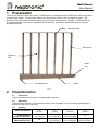
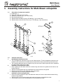
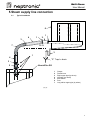
Multi-Steam Steam dispersion system Installation instructions & user manual READ AND SAVE THESE INSTRUCTIONS MS-EN/121219 Multi-Steam Foreword Foreword 1. These installation instructions and user manual have been developed to facilitate the installation and the operation of the Multi-Steam. The strict application of these instructions will ensure the conformity of your installation and operation as per manufacturer's recommendations. 2. The application of these instructions is one of the conditions for the application of the warranty. 3. The application of these instructions does not ensure at any time conformity to procedures, regulation or local codes. 4. 2012: All right reserved, this document cannot be reproduced totally or partially by any means whether, electronic, mechanical, photocopy, recording or other, without prior written authorization of National Environmental Products Ltd. Manufacturer Presentation National Environmental Products Ltd. (NEP) is the owner of the Neptronic brand. NEP develops, manufactures and services a complete line of: Steam humidifiers for commercial and residential application, Actuators to regulate air damper or valves, Electric heaters, Humidistats, Thermostats and other control peripherals used to control HVAC equipment. For more information about our products, visit our web site at www.neptronic.com Each Neptronic product benefits from over 25 years of experience of our qualified staff. From the inspiration to realization, innovation has been the standard in design. As the result of this dedication, NEP Ltd. owns several patents, notably the ENERDRIVE system and the AFEC system. Manufacturing is conducted on the premises of our modern 80,000 sq.ft. (7 000m2) facility in Montreal, Canada. Our quality system is built on the ISO 9001 model. Our vision '' A Customer for Life'' is realized by listening our customers’ needs and by supplying them with products, which exceed their expectations in quality, functionality and durability. National Environmental Products Ltd. Tel. (Toll free in North America): 1 800 361-2308 Tel.: (1) (514) 333-1433 Fax: (1) (514) 333-3163 Fax Customer service: (514) 333-1091 Business hours: Monday to Friday, 8:00am to 5:00pm (Eastern time) i Multi-Steam Table of contents Table of contents Foreword & Manufacturer Presentation…....………………………………………………………………………………………..i 1. 2. 2.1. 2.2. 2.3. 3. 3.1. 3.2. 4. 4.1. 4.2. 4.3. 4.4. 4.5. 5. 5.1. 5.2. 5.3. 5.4. 5.5. 5.6. 6. 7. 8. Presentation ............................................................................................................................................................... 2 Characteristics ........................................................................................................................................................... 2 Accessories ............................................................................................................................................................ 2 Dimensions............................................................................................................................................................. 2 Capacity.................................................................................................................................................................. 2 Assembly instructions for Multi-Steam collapsible..................................................................................................... 3 Description of components supplied ...................................................................................................................... 3 Assembly instruction............................................................................................................................................... 3 Mechanical installation ............................................................................................................................................... 4 General recommendations ..................................................................................................................................... 4 Pitch (Horizontal air flow)........................................................................................................................................ 4 Typical installation of Multi-Steam (Horizontal air flow).......................................................................................... 4 Pitch (Vertical air flow)............................................................................................................................................ 5 Typical installation of Multi-Steam (Vertical air flow).............................................................................................. 5 Steam supply line connection .................................................................................................................................... 6 Typical installation .................................................................................................................................................. 6 General recommendations ..................................................................................................................................... 7 Single steam outlet ................................................................................................................................................. 8 Multiple steam outlets............................................................................................................................................. 8 Multiple steam outlets (Multiple humidifiers) .......................................................................................................... 8 Condensate Drain outlet......................................................................................................................................... 8 Start up procedure ..................................................................................................................................................... 9 Maintenance............................................................................................................................................................... 9 Troubleshooting guide................................................................................................................................................ 9 General condition of sales & warranty…..…….……………………………………………………………………………….….10 1 Multi-Steam User Manual 1. Presentation Thank you for choosing a Neptronic product. The Multi-Steam is a multiple stainless steel dispersion tubes connected to a stainless steel header. The Multi-Steam manifold is custom built for the duct or the air handling unit (AHU). The dispersion tubes include brass insertion nozzles (eyelets) to prevent condensate from escaping. The Multi-Steam can be completely welded at the factory or collapsible for field assembly. Multi-Steam manifolds are used for very short absorption distances. Mounting bracket Brass eyelet Dispersion tube Steam inlet Condensate drain Header (Fig. 1) 2. Characteristics 2.1. Accessories Typical accessories include the hose, clamps and MS connection. 2.2. Dimensions The Multi-Steam manifold is custom build for the duct or the air handling unit (AHU), so dimension depends on dimension of the duct or of the AHU. 2.3. Capacity Steam inlet diameter Capacity Electric SK300 and SKE series Capacity gas SKG and SKGE series 2 in (51 mm) 0 to 66 lbs/hr (0 to 30 kg/hr) n/a 3 in (76 mm) 67 to 270 lbs/hr (31 to 122 kg/hr) 0 to 210 lbs/hr (0 to 100 kg/hr) 4 in (108 mm) 271 to 540 lbs/hr (123 to 245 kg/hr) 5 in (133 mm) 211 to 405 lbs/hr (101 to 200 kg/hr) 406 to 560 lbs/hr (201 to 255 kg/hr) n/a 2 Multi-Steam User Manual 3. Assembly instructions for Multi-Steam collapsible 3.1. 1) 2) 3) 4) 5) 6) Description of components supplied Header (qty: 1) Dispersion tubes (qty: as per order) Gaskets p/n SP 6867 (qty: 1 per vertical tube) Mounting bracket (qty: 1) Stainless steel bolts M5-0.8 s/s p/n SP 6869 (qty: 1 per vertical tube) Stainless steel screws M5-0.8x10mm s/s p/n SP 6868 (qty: 4 per vertical tube) DETAIL B DETAIL A (fig. 2) 3.2. 1. 2. 3. Assembly instruction Identifying the distribution tubes Two of the dispersion tubes have only one row of brass eyelets. These two dispersion tubes are to be installed at the extremities of the header steam outlets with the brass eyelets facing toward the inside. The remaining dispersion tubes are identical, they have two rows of brass eyelets and to be installed on the others steam outlets of the header. Installation of the distribution tubes Place a gasket over the steam outlet of the header. Align the holes on the gasket with the holes on the header (detail A). Align the mounting plate holes of the distribution tube with the holes on the gasket. Use four screws to secure the distribution tube to the header. Repeat step 2 for the remaining distribution tubes. Installation of the mounting bracket Place the mounting bracket on top of the distribution tubes, the bents on the bracket should be facing toward the top (detail B). Align the holes on the mounting bracket with each stud screws on the distribution tubes. Use the bolts to secure the mounting bracket to all the distribution tubes. 3 Multi-Steam User Manual 4. Mechanical installation 4.1. General recommendations 4.2. IMPORTANT: Mechanical installation should conform to Local and National Codes. Location: Plan a location which is easy to access in order to permit a proper installation and inspection of Multi-Steam. The Multi-Steam is centered side to side in the duct or across the face of a coil in an air handler. In order to protect against water damage, it is recommended that a sealed section of duct or a drip pan with drain should be installed beneath the Multi-Steam. Pitch (Horizontal air flow) 4.3. Installing the Multi-Steam inside a horizontal air flow duct or in an AHU, you must ensure that the mounting bracket is level horizontally. The Multi-Steam’s header is already pitched toward the condensate drain from the factory when the multiple dispersion tubes are level vertically. The eyelets must be perpendicular to the airflow. Typical installation of Multi-Steam (Horizontal air flow) Rod, bolt, nut and washer assembly by others Mounting bracket must be level horizontally Duct Steam hose and clamps Dispersion tube Pitch Condensate drain Steam trap by others Condensate drain pipe by others Header Floor drain (Fig. 3) 4 Multi-Steam User Manual 4.5. Pitch (Vertical air flow) Installing the Multi-Steam inside a vertical air flow duct, you must ensure that the header is pitch properly. The Multi-Steam header must be pitch toward the condensate drain. A minimum of 10 degree pitch must be kept on the dispersion tubes to allow the condensate to flow toward the header. The eyelets must be perpendicular to airflow. Typical installation of Multi-Steam (Vertical air flow) Air duct Air flow 4.4. Rod, bolt, nut and washer assembly (by others) 10% slope is integrated in header design Air flow Steam supply hose or rigid insulated pipe to Humidifier (by others) Condensate drain pipe (by others) Steam trap & Floor drain (by others) Neptronic Humidifier (Fig. 4) 5 Multi-Steam User Manual 5. Steam supply line connection 5.1. Typical installation 6 3 1 4 7 1 2 15 % 3 1 4 ''S'' Trap to drain 3 2 Humidifier SK 1 2 3 4 5 6 7 Clamps Flexible hose Rigid copper pipe (by others) Insulation (by others) Multi-Steam Duct Long radius copper pipe (by others) (Fig. 5) 6 Multi-Steam User Manual 5.2. General recommendations Follow these general installation rules in order to avoid any condensation accumulation which can cause severe water accumulation in the duct or a humidifier malfunction. IMPORTANT: Risk of malfunction. Avoid kinks, sags and areas where condensate can become trapped. Plumbing installation should conform to Local and National Codes a) The slope of the steam hose (rigid or flexible) should not be less than 15% (7 horizontal lengths for 1 vertical length) in order to ensure continuous drainage of condensation back to humidifier or to steam trap. 15% ''S'' Trap to drain b) c) d) The lowest point of any steam hose or rigid pipe must be the humidifier. If necessary a steam trap (S Type) should be installed higher than the static pressure of the system by at least 2 inches (51mm). 15% Total length of the steam hose or rigid pipe should not exceed 15 feet (5 meters). Longer runs will result in added condensation losses. Whenever possible, use insulated copper piping. Flexible steam hose should be used for short runs (up to 15 feet or 5m) or for interconnecting between the rigid pipe runs. For longer runs, please consult the factory. ''S'' Trap to drain Correct installations Whenever using rigid copper pipe, use insulation to diminish condensation build up. Kinks Sag Missing ''S'' trap Incorrect installation (Fig. 6) 7 Multi-Steam User Manual 5.3. 5.4. Single steam outlet Run one steam line from the steam outlet of the evaporation chamber of the humidifier to the MultiSteam header (a reducer is welded at the inlet of the Multi-Steam header). Use steam hose and clamps to make the connection from hard insulated copper pipe to the Multi-Steam and the humidifier. Multiple steam outlets If the humidifier supplying the steam has more than one steam outlet from the evaporation chamber a MS connector must be ordered with the Multi-Steam. Install the same number of steam lines as the steam outlets from the evaporation chamber to the MS connector. Position the MS connector close to the humidifier or to the Multi-Steam while maintaining the proper pitch. IMPORTANT: Never reduce the diameter of the steam lines. Improper size will over-pressurize the humidifier. 5.5. Multiple steam outlets (Multiple humidifiers) If multiple humidifiers are supplying the steam to the Multi-Steam, multiple MS connectors must be ordered with the Multi-Steam. Install the same number of steam lines as the steam outlets from the evaporation chamber to the MS connector. Position the MS connectors close to the humidifier or to the Multi-Steam while maintaining the proper pitch. IMPORTANT: Never reduce the diameter of the steam lines. Improper size will over-pressurize the humidifier. 5.6. Condensate Drain outlet The Multi-Steam has a 1/2” (15mm) or 3/4” (20mm) NPT (or BSPT) condensate drain connection. IMPORTANT: Remove the 1/2” (15mm) or 3/4" (20mm) cap (shipping protection) from the condensate drain before the installation. Run a pipe (same size as the condensate drain connection) as directly as possible from the condensate drain outlet to the floor drain with a proper slope and install a steam trap to prevent any steam leakage from the drain. The steam trap (S Type) should be installed higher than the static pressure of the system by at least 2 inches (51mm). 8 Multi-Steam User Manual 6. Start up procedure Follow this start-up procedure to avoid improper system operation: Ensure that plumbing connections have been done in accordance with the instructions in this manual. a) Verify that the steam supply line is connected properly to the Multi-Steam. b) Verify that the Multi-Steam is properly pitched. c) Verify that the Multi-Steam condensate drain is connected to the drain line. 7. Maintenance Inspect the Multi-Steam at start up and during normal operation. 8. Troubleshooting guide Problem Causes Multi-Steam discharges water inside the duct or AHU. Steam supply line is not insulated. Steam supply line is not properly drained or sloped. The Multi-Steam condensate drain is blocked or drain line is not properly sloped. The Multi-Steam is not properly pitched. Steam or condensate is leaking from the gasket on the Multi-Steam collapsible. Corrective actions Insulated the steam supply line. Install steam trap to remove the condensate from the steam supply line. Slope the steam supply line properly as per instruction. Verify the condensate drain line. Pitch the Multi-Steam as per instructions. Replace the gasket (p/n SP 6867). 9 Multi-Steam General conditions of sale & warranty 1. General Unless otherwise arranged, in writing, the acceptance of the Order Confirmation by the purchaser includes acceptance of the "General Conditions of Sale and Warranty" of National Environmental Products, Ltd hereafter referred to as NEP. 2. Incoterms The international rules for interpretation of trade terms "Incoterms" as defined by the ICC Incoterms publication no. 460 from 1990, shall apply to the commercial terms used herein. 3. Confirmation of Order NEP shall not be deemed to have accepted an order until written "Order Confirmation" from NEP is issued to the purchaser. It is the responsibility of the purchaser to verify that all information concerning his/her order is correct and to notify NEP In writing, of any discrepancy prior to the order being shipped. In the event of a change or correction to an existing order, a second "Order Confirmation" will be issued by NEP. 4. Price Our prices are net, Ex-works Montreal in U.S. Currency, unless stated otherwise. Minimum orders shall be $50.00 minimum. Shipping and Handling charges are $5.00 minimum per order unless the shipment is billed to the purchaser's account or shipped freight collect. NEP reserves the right to adjust accepted prices in the event of alterations in rates of exchange, variations in costs of materials, changes in wages, interference on the part of the Government or similar conditions over which NEP has no control. 5. Payments terms Major credit cards, C.O.D., Prepayment. For open account, invoices are payable within 30 days from the date of invoice without no deduction, unless specify otherwise. An interest charge of 2% per month will be included on all overdue payments. No new order will be process if invoices are not paid within 45 days. 6. Transfer of ownership The goods shall remain the property of NEP until the full payment for the goods has been received by NEP. 7. Delivery terms Shipments are Ex-works 400 Lebeau, St Laurent, Quebec, H4N 1R6, CANADA unless notified otherwise. Unless special instructions, the order will be delivery in the way which NEP deems best without guaranteeing this to be the cheapest way of transport. For International Order, a written designation naming the freight forwarding agent is required and will remain in effect until notified otherwise. Any discrepancy, damage or breakage should be reported in writing both to NEP and to the Carrier within 5 working days from the receipt date. 8. Risk From the moment of delivery, the purchaser shall bear all risks for the goods and NEP shall not be responsible for loss and damage incurred during transportation. 9. Delivery time Delivery time is stated approximately and depends on the product ordered, please allow a minimum of: a) 2 weeks for processing North American order. b) 6 weeks for processing International order. We will make every effort to adhere to our delivery promises, but will not accept order or contract cancellation or any liability for any direct or indirect losses that may arise for any reason whatsoever as a result of our failure to adhere to such promises. 10. Return of good Goods received by the purchaser cannot be returned unless a completed "R.M.A. Form" (Return Material Authorization Form) has been issued by NEP's Customer Service. Any returned goods must be sent to NEP 400 Lebeau, St Laurent, Quebec, H4N 1R6, CANADA, unless stated otherwise by the R.M.A. Form, accompanied with the completed "R.M.A. Form", the R.M.A. number shall be prominently displayed on the shipping box. Unauthorized returns will be refused. Any returned goods must be sent freight prepaid. Any goods that come to us freight collect will be refused and returned to sender unless previously agreed to by us in writing on the "R.M.A. Form". Goods returned for credit shall be in condition for resale in the original box and properly packaged. Units, accessories or components that have been installed are not returnable and not refundable. Credit is subject to an overhead charge of 30% of the invoice plus shipping & handling if returned within 30 days of the invoice date and 50% from 30 to 60 days. Non standard product (SK units with special feature), Multisteam manifolds and any DI unit are not returnable and not refundable. 11. Warranty Provided that the terms of payment are observed, the purchaser is offered a warranty of 24 months from the original purchase date of delivery for any NEP's standard product, provided the equipment has been properly installed and operated in accordance with NEP instructions. The warranty covers faulty manufacture, design and/or defective materials. The warranty shall cease to be valid in the event of misapplication, incorrect installation, improper maintenance or any other incorrect uses or misuse of the product. For the SK series, the warranty furthermore ceases to be valid if the user disconnects or removes any electronic or mechanical components prior disconnecting the input power. NEP assumes no responsibility for repairs made on equipment, unless performed by NEP's authorized personnel. The defective product or component shall be returned in accordance with the paragraph 10 (Returns of goods) as described in this document. NEP agrees under the warranty to repair or replace (at the discretion of NEP) such standard product or component, which upon examination by NEP are found to be defective. Product or component replaced or repaired under warranty will be sent back to the purchaser, standard freight paid by NEP Expenses in connection with travelling time, dismantling and mounting shall not be paid by NEP Guarantee for products or components sold but not manufactured by NEP, is only given to the same extent as given to NEP, however, not exceeding the normal NEP warranty. Parts used for repairs are warranted for the balance of the term of the warranty on the original humidifier or 90 days, whichever is longer. Any repair made, after the original warranty period, at the NEP facilities are warranted for 1 month from the date of repair. 12. Proper law and jurisdiction This contract is and shall be deemed to have been made in the province of Quebec, CANADA, and shall in all respects, be governed by the province of Quebec laws. 10