1
User Manual for the
HE300GEN200
Genius Serial Bus Interface
Option Card for GE Drives
AV-300/DV-300
Adjustable Speed Drives
Third Edition
05 December 2000
MAN0018-03
MAN0018-03
05 DEC 2000
PAGE 3
PREFACE
This manual explains how to use the Horner APG Genius Serial Interface card for use with the GE AV300 and DV-300 drives.
Copyright (C) 2000 Horner APG, LLC., 640 North Sherman Drive Indianapolis, Indiana 46201. All rights
reserved. No part of this publication may be reproduced, transmitted, transcribed, stored in a retrieval
system, or translated into any language or computer language, in any form by any means, electronic,
mechanical, magnetic, optical, chemical, manual or otherwise, without the prior agreement and written
permission of Horner APG, LLC.
All software described in this document or media is also copyrighted material subject to the terms and
conditions of the Horner Software License Agreement.
Information in this document is subject to change without notice and does not represent a commitment on
the part of Horner APG, LLC.
Series 90-30 is a trademark of GE Fanuc Automation.
AV-300 and DV-300 drives are trademarks of GE Motors & Industrial Systems.
Note: This manual is to be used in conjunction with the AV-300/DV300 instructions manuals, the
GECFG300 software configuration help file, and the GE Fanuc Genius I/O System and
Communications (GEK-90486F-1) User’s Manual.
For user manual updates, contact Horner APG, Technical Support
Division, at (317) 916-4274 or visit our website at www.heapg.com.
PAGE 4
05 DEC 2000
MAN0018-03
LIMITED WARRANTY AND LIMITATION OF LIABILITY
Horner APG, LLC. ("HE-APG") warrants to the original purchaser that the Option Card manufactured by
HE-APG is free from defects in material and workmanship under normal use and service. The obligation
of HE-APG under this warranty shall be limited to the repair or exchange of any part or parts which may
prove defective under normal use and service within two (2) years from the date of manufacture or
eighteen (18) months from the date of installation by the original purchaser whichever occurs first, such
defect to be disclosed to the satisfaction of HE-APG after examination by HE-APG of the allegedly
defective part or parts. THIS WARRANTY IS EXPRESSLY IN LIEU OF ALL OTHER WARRANTIES
EXPRESSED OR IMPLIED INCLUDING THE WARRANTIES OF MERCHANTABILITY AND FITNESS
FOR USE AND OF ALL OTHER OBLIGATIONS OR LIABILITIES AND HE-APG NEITHER ASSUMES,
NOR AUTHORIZES ANY OTHER PERSON TO ASSUME FOR HE-APG, ANY OTHER LIABILITY IN
CONNECTION WITH THE SALE OF THIS OPTION CARD. THIS WARRANTY SHALL NOT APPLY TO
THIS OPTION CARD OR ANY PART THEREOF WHICH HAS BEEN SUBJECT TO ACCIDENT,
NEGLIGENCE, ALTERATION, ABUSE, OR MISUSE.
HE-APG MAKES NO WARRANTY
WHATSOEVER IN RESPECT TO ACCESSORIES OR PARTS NOT SUPPLIED BY HE-APG. THE
TERM "ORIGINAL PURCHASER", AS USED IN THIS WARRANTY, SHALL BE DEEMED TO MEAN
THAT PERSON FOR WHOM THE OPTION CARD IS ORIGINALLY INSTALLED. THIS WARRANTY
SHALL APPLY ONLY WITHIN THE BOUNDARIES OF THE CONTINENTAL UNITED STATES.
In no event, whether as a result of breach of contract, warranty, tort (including negligence) or otherwise,
shall HE-APG or its suppliers be liable of any special, consequential, incidental or penal damages
including, but not limited to, loss of profit or revenues, loss of use of the products or any associated
equipment, damage to associated equipment, cost of capital, cost of substitute products, facilities,
services or replacement power, down time costs, or claims of original purchaser's customers for such
damages.
To obtain warranty service, return the product to your distributor with a description of the
problem, proof of purchase, post paid, insured and in a suitable package.
ABOUT PROGRAMMING EXAMPLES
Any example programs and program segments in this manual or provided on accompanying diskettes are
included solely for illustrative purposes. Due to the many variables and requirements associated with any
particular installation, Horner APG cannot assume responsibility or liability for actual use based on the
examples and diagrams. It is the sole responsibility of the system designer utilizing the product to
appropriately design the end system, to appropriately integrate the product and to make safety provisions
for the end equipment as is usual and customary in industrial applications as defined in any codes or
standards which apply.
Note: The programming examples shown in this manual are for illustrative
purposes only. Proper machine operation is the sole responsibility of the
system integrator.
MAN0018-03
05 DEC 2000
PAGE 5
Revisions to This Manual
This version (MAN0018-03) of the HE300GEN200 User Manual contains the following revisions,
additions and deletions:
1. Revised Section 8.3, Item F, 1 to set Jumper JP1.
2. Converted manual into standard format.
3. Changed company name from Horner Electric, Inc. to Horner APG, LLC.
PAGE 6
05 DEC 2000
MAN0018-03
MAN0018-03
05 DEC 2000
PAGE 7
Table of Contents
PREFACE................................................................................................................................................3
ABOUT PROGRAMMING EXAMPLES ....................................................................................................4
Revisions to This Manual .........................................................................................................................5
CHAPTER 1: INTRODUCTION ...............................................................................................................9
CHAPTER 2: DRIVE OVERVIEW .........................................................................................................11
CHAPTER 3: GENIUS – SBI COMMUNICATION..................................................................................13
3.1
Genius SBI Operation ..............................................................................................................13
3.2
Automatic Data Transfer ..........................................................................................................13
3.3
SBI to/from GBC Communication using Global Data.................................................................14
3.4
Datagrams ...............................................................................................................................15
3.4.1
Read Device (1EH) Datagram Header Format...................................................................16
3.4.2
Write Device (20H) Datagram Header Format ...................................................................16
3.4.3
Specific Operations ...........................................................................................................17
3.4.4
Sequential Write Device ....................................................................................................18
3.4.5
Random Write Device .......................................................................................................19
3.4.6
Sequential Read Device....................................................................................................19
3.4.7
Random Read Device .......................................................................................................20
3.4.8
Read Device Reply ...........................................................................................................20
3.4.9
Miscellaneous Information About Datagrams.....................................................................21
CHAPTER 4: GENIUS COMMUNICATIONS.........................................................................................23
4.1
Introduction to Genius ..............................................................................................................23
4.2
Network Architecture................................................................................................................23
4.3
Genius Communications Services ............................................................................................24
4.4
I/O Service...............................................................................................................................24
4.5
Global Data..............................................................................................................................24
4.6
Datagrams ...............................................................................................................................24
CHAPTER 5: PLC CONFIGURATION...................................................................................................25
5.1
PLC Configuration....................................................................................................................25
5.2
Series 90-70 Configuration.......................................................................................................25
5.2.1
%I Length (Default = 16) ...................................................................................................26
5.2.2
%Q Length (Default = 16)..................................................................................................26
5.2.3
%AI Length (Default = 6) ...................................................................................................26
5.2.4
%AQ Length (Default = 1) .................................................................................................26
5.2.5
Reference Addresses........................................................................................................26
5.2.6
Redundancy......................................................................................................................27
5.2.7
Input Default .....................................................................................................................27
5.2.8
Outputs Enabled ...............................................................................................................27
5.3
Series 90-30 Configuration.......................................................................................................27
5.3.1
Device Type......................................................................................................................28
5.3.2
Input References (Input 1 Ref, Input 2 Ref)........................................................................28
5.3.3
Input Length (Input 1 Len, Input 2 Len)..............................................................................28
5.3.4
Output References (Output 1 Ref, Output 2 Ref) ...............................................................28
5.3.5
Output Length (Output 1 Len, Output 2 Len)......................................................................28
CHAPTER 6: AV-300 / DV-300 DRIVE PARAMETERS.........................................................................29
6.1
Drive Parameter Descriptions...................................................................................................29
6.2
DIRECTION: ............................................................................................................................29
6.3
ACCESS METHOD:.................................................................................................................29
6.4
LOW PRIORITY TO/FROM DRIVE: .........................................................................................29
6.5
HIGH PRIORITY TO/FROM DRIVE: * ......................................................................................29
6.6
LOW PRIORITY DISCRETE BIT WORD TO/FROM DRIVE: ....................................................29
6.7
HIGH PRIORITY DISCRETE BIT WORD TO/FROM DRIVE: * .................................................29
PAGE 8
05 DEC 2000
MAN0018-03
CHAPTER 7: WIRING DIAGRAMS .......................................................................................................31
7.1
Genius Wiring: .........................................................................................................................31
7.2
RS232/RS485 Pinout: ..............................................................................................................32
CHAPTER 8: INSTALLING THE SBI CARD ..........................................................................................33
8.1
Installation Hardware................................................................................................................33
8.2 Required Tools .............................................................................................................................33
8.3
The installation procedures. .....................................................................................................33
8.4
Grounding the AV/DV 300 GE Drive Genius SBI Option Card...................................................36
8.4.1
Installation.........................................................................................................................36
CHAPTER 9: SBI CARD LED INDICATORS .........................................................................................39
9.1
“Power” Indicator......................................................................................................................39
9.2
“Reset” Indicator ......................................................................................................................39
9.3
“Transmit” Indicator ..................................................................................................................39
9.4
“Receive” Indicator...................................................................................................................39
9.5
“GENA OK” Indicator................................................................................................................39
9.6
“COMM OK” Indicator ..............................................................................................................39
APPENDIX A: HE300GEN200 ECHO TEST TIMING RESULTS ...........................................................41
A.1 Test Setup: ..............................................................................................................................41
A.2 Setup .......................................................................................................................................41
A.3 General Procedure...................................................................................................................41
A.4 HIGH PRIORITY I/O TEST.......................................................................................................41
A.5 LOW PRIORITY I/O TEST: ......................................................................................................42
A.6 DGFC I/O TEST:......................................................................................................................42
A.7 High Priority Test .....................................................................................................................42
A.8 Low Priority Test ......................................................................................................................43
A.9 OLD VS NEW (Version 1.09 VS Version 1.10) .........................................................................43
A.10 Genius SBI Internal Timing Result:...........................................................................................43
A.11 High Priority Timing..................................................................................................................43
A.12 Low Priority Timing:..................................................................................................................44
APPENDIX B: TECHNICAL SUPPORT.................................................................................................45
INDEX ...................................................................................................................................................47
MAN0018-03
05 DEC 2000
PAGE 9
CH. 1
CHAPTER 1: INTRODUCTION
The HE300GEN200 is a Genius Serial Bus Interface (SBI) that resides in the AV300 and/or DV300
adjustable speed drive.
The SBI card is GENA based. Since the GENA interface board is a “slave” only Genius communications
device, it cannot control other devices on the Genius bus or look at other device data. Communication
can only be coordinated via a “master” device such as a Genius Bus Controller (GBC). This is
accomplished in the standard Genius format by sending Broadcast (Global) Data to the GBC, and
listening to Directed Control Data from the GBC. The SBI allows up to 32 words of Broadcast Data and
up to 16 words of Directed Data to be configured per drive.
To maintain flexibility with future parameter numbers, the SBI does not have parameter information hard
coded into its memory. All of the required parameter information must be configured and loaded into the
SBI. This is accomplished using the GECFG300 software configuration tool or through Genius
datagrams.
Note: The GECFG300 software configuration tool can be purchased through Horner APG, LLC.
PAGE 10
CH. 1
05 DEC 2000
NOTES
MAN0018-03
MAN0018-03
05 JUN 2000
PAGE 11
CH. 2
CHAPTER 2: DRIVE OVERVIEW
It is important to understand the inner workings of the drive before understanding the Genius Serial Bus
Interface (SBI) operation.
The Genius SBI accesses values in the drive by means of predefined parameter numbers. These
parameter numbers are contained in the drive, and are described in the AV-300/DV-300 instruction
manual. The SBI can communicate with the drive and the DGFC.
The DGFC-386 option card (DGFC) is another option for the AV-300/DV-300 drive. This card is mounted
directly to the left of the SBI card. The DGFC also contains parameter numbers, independent of the
drive’s parameter numbers. The difference is that the DGFC does not have predefined parameter
numbers. The user has to program these parameter numbers.
The parameters in both the drive and the DGFC can be a length of either 1 or 2 words. The predefined
drive parameters also have predetermined data types (Integer, Unsigned Integer, Float, etc.). The data
type determines the data length. An Integer is 1 word and a Float is 2 words. The DGFC has variable
data types for each user-defined parameter. The data type is not fixed like the drive parameter data
types.
The SBI has four different access methods used to communicate with the drive. These are low priority
word, high priority word, high priority discrete bits (Virtual I/O) and low priority discrete bits.
The
parameter table in the AV300/DV300 manual is used to determine the access method available for a
given parameter number. Low priority word access can be used to communicate with all of the drive
parameter numbers defined as type R (read), W (write), Z (write only when drive disabled), and/or C
(command parameter-the writing of any value causes the execution of a command) in the RS485 column
(located in the parameter tables of the AV-300/DV-300 Instructions Manual).
Table 2.1 – SBI Access Methods
SBI Access Method
Description
Low Priority Word
All Fixed Parameters (R, W, C, Z) 16 or 32 Bit.
High Priority Word
R, W, Z Fixed parameters, 16 bit.
Low Priority Word
Variable DGFC Parameters.
High Priority Discrete Bits
(Virtual I/O)
R, W, Z Maximum of 16 Bits.
Low Priority Discrete
Bits
R, W, Z Maximum of 16 bits.
When accessing the drive, the length will be either one or two words depending on the FORMAT column
(located in the parameter tables of the AV-300/DV-300 Instructions Manual). The high priority word
access can be used with all of the drive parameters defined as type R, W and/or Z in the PDC column
and have a minimum value of 0 and a maximum value greater than one. The length of high priority word
access is fixed at one word.
The only way to communicate directly with the DGFC is with low priority word access. When accessing
the DGFC, the length depends on the data type value defined in the DGFC manual. Due to the
differences between the drive and the DGFC, the SBI requires the source/destination, parameter number,
and parameter information. The source/destination is the drive or the DGFC (The SBI needs to know
where to retrieve (source) or send (destination) the data). The parameter number is either a predefined
PAGE 12
CH. 2
05 DEC 2000
MAN0018-03
drive parameter number or a user programmed DGFC parameter number. This information tells the SBI
where to access the value (the drive or DGFC). The parameter information contains two pieces of
information. One piece is the data type, and the other piece is the access method. In the case of the
drive, the data type determines the number of words required for the parameter number. In the case of
the DGFC, the data type is a number representing an Integer, Unsigned Integer, Float, etc.
Note: The software configuration tool GECFG300 sets up this information for Global and Discrete
Control Data. The user must provide this information when using Genius datagrams to
access the data.
See the datagrams section for more information.
High priority communication with the DGFC is accomplished by high priority communication from the SBI
to the scratch pad and Synchronous communication from the scratch pad to the DGFC.
The high priority discrete bits (Virtual I/O) are identified by R, W and/or Z in the PDC column and a
minimum value of zero and a maximum value of one. The SBI allows up to 16 high priority and 16 low
priority discrete bits to be configured. The low priority discrete bits are identified as a low priority word
with a minimum of zero and a maximum of one. Both the high and low priority discrete bits are accessed
as a bit packed word. In the case of the high priority bits, there is a pre-configuration done between the
SBI and the drive. This allows the SBI and the drive to access the bit packed word directly. The low
priority bit access is equivalent to doing up to 16 low priority word accesses. This is important to
remember when configuring the SBI due to the fact that the low priority bit access will take a greater
amount of time to process than will a normal low priority data word.
MAN0018-03
05 DEC 2000
PAGE 13
CH. 3
CHAPTER 3: GENIUS – SBI COMMUNICATION
3.1
Genius SBI Operation
There are two types of Genius communication that can be used between the Genius Bus Controller
(GBC) and the SBI, automatic data transfer and datagrams.
The automatic data transfer type is the most common. This type of communication uses broadcast
(global) data to transfer information from the SBI to the GBC, and directed control data to transfer
information from the GBC to the SBI. With this data type, the GBC is always communicating with the SBI.
The datagram type requires the GBC to use read device and write device datagrams to communicate with
the SBI. Datagrams are used for slow changing data or infrequent read/write operations.
The two types of communication are described in detail in the following sections.
3.2
Automatic Data Transfer
To communicate with Genius using Automatic Data Transfer, all of the required parameter information
previously discussed in the Drive Overview section (the global data to transfer information from the SBI,
and Directed Control Data to transfer data from the GBC to the SBI) must be configured and loaded into
the SBI.
The SBI configuration is accomplished using the GECFG300 software configuration tool. The
configuration consists of 2 memory maps, the global data memory map and the directed control data
memory map. The memory maps associate parameter numbers and parameter information with
corresponding data words. The GECFG300 configuration tool uses “pick lists” for choosing parameter
numbers. The pick lists change depending on which access method is chosen. This eliminates the need
to manually determine all of the information described in the Drive Overview section.
The global data memory map contains a parameter number and parameter information for each global
data word from the drive to the GBC. The directed control data memory map contains a parameter
number and parameter information for each directed control word from the GBC to the drive. Once the
memory maps are created using GECFG300, they are downloaded into the SBI non-volatile memory.
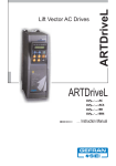
Figures 3.1 and 3.2 are examples of a global data configuration and a directed control data configuration.
The software configuration tool is setup in such a manner so that when the user chooses a parameter
from the “picklist”, that parameter is set at that global data word. When the SBI scans a configuration, it
separates the high priority words and the low priority words and stores them in two different arrays. The
data is then scanned sequentially from each array, depending on where it is at in the scan cycle. The
high priority words are scanned first and more frequently then the low priority. For more information on
the scanning sequence, see chapter 2. The following is a brief example of a Global data configuration.
The global data configuration is configured to have the SBI send parameter 503 (pad 0) in global data
word 0, parameter 504 (pad 1) in global data word 1, and parameter 1 (speed minimum amount) in global
data words 2 and 3. See Figure 3.1.
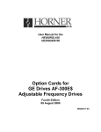
The directed control data configuration looks the same as the global data configuration. It is designed to
allow the SBI to receive the value for parameter 503 in directed data word 0, the value for parameter 504
in directed data word 1 and the value for parameter 1 in directed data words 2 and 3. See Figure 3.2.
NOTE: The following sections will reference these figures.
PAGE 14
CH. 3
3.3
05 DEC 2000
MAN0018-03
SBI to/from GBC Communication using Global Data
After the global data configuration is downloaded from the configuration tool to the SBI, the SBI will start
retrieving values from the drive for the configured parameter numbers. Referring to Figure 3-1 and 3-2,
the SBI will first scan all the high priority data and store it in the corresponding global data locations.
During a high priority scan, the SBI: reads the high priority word, reads the high priority bits, writes the
high priority word, and writes the high priority bits in that order.
The SBI will then retrieve the value in the drive at parameter 503 (Low Priority From Drive) using the low
priority method and store it in global data word zero. Then the high priority parameters will be scanned
again in the same manner as before. The SBI will then retrieve the data from Directed Control data word
zero, and write it to parameter 503 (Low Priority to Drive). The data is continuously read in this manner
(scanning the high priority data, reading low priority data, scanning high priority data again, and writing
low priority data).
While the low priority read or write is waiting for command response from the drive, the high priority data
is scanned until the drive responds, or a “timeout” occurs.
The SBI will continually update all of the global data words with the values of the corresponding
parameter numbers. The parameter number source, access method and data type/length is determined
by the associated parameter information that was also configured along with the parameter number.
The directed control data communication works on a change detect basis (once the SBI recognizes that a
directed control data word has changed, it writes the value to the corresponding parameter).
Refer to Figure 3-2. If directed control data word zero changes, then the SBI detects the change and
writes the value stored in directed control data word zero to parameter 503 in the drive using the low
priority method. If either directed control data words two or three change then the SBI will write directed
control data words two and three to parameter one in the drive using the low priority method.
The parameter destination, access method and data type/length is determined by the associated
parameter information that was also configured along with the parameter number.
Figure 3.1 - Global Data Transfers
MAN0018-03
05 DEC 2000
PAGE 15
CH. 3
Figure 3-2: Directed Control Data
3.4
Datagrams
There is no configuration in the SBI to handle parameter access using datagrams. Unlike the automatic
data transfer method, the GECFG300 software configuration tool is not used. Therefore, the vital
parameter information must be contained in the datagram.
The access method is always low priority word to either the drive or the DGFC. There are two datagram
message types used by the master controller to access drive and/or DGFC parameters, Read Device
(1EH) and Write Device (20H). Read Device is used to retrieve data from the drive. The SBI responds to
the Read Device datagram with a Read Device Reply (1FH).
The Read Device Reply will contain drive and/or DGFC parameter values that the master requested in
the Read Device datagram. Write Device is used to write values to the drive and/or DGFC.
The SBI does not respond to a Write Device datagram.
The following are descriptions of the COMMREQ header formats that the 90-30 bus controller uses to
send datagrams. Refer to GFK-1034B Series 90-30 Genius Bus Controller manual for more details. The
header information is independent of the data bytes that are necessary to access drive and/or DGFC
parameters. The data bytes are described in detail in the Specific Operations Section.
PAGE 16
CH. 3
3.4.1
05 DEC 2000
MAN0018-03
Read Device (1EH) Datagram Header Format
This format is used by COMMREQ #15: Request Datagram Reply
Table 3.1 – Read Device (1EH) Datagram Header Format
Address #
Address
Address+1
Address+2
Description
Command Length
No wait
Status Block mem type
Value
# of words (Address+ 6 to Data Byte n)
Always 0
(See the AV300/DV300 Manual)
Address+3
Status Block Offset
Beginning address for status
Address+4
Address+5
Address+6
Address+7
Address+8
Address+9
Address+10
Idle timeout value
Max com time
Command Number
Device Number
Function Code
Subfunction Code
Priority
0
0
15
0-31
32 (20H)
30 (1EH)
0 (Normal) 1 (High Priority)
Address+11
Datagram length
# of Bytes (Add.+16 to Data Byte n)
Address+12
Address+13
Address+14
Reply Subfunction
Reply memory type
Reply memory offset
31 (1FH)
(See the AV300/DV300 Manual)
Starting Address
Address+15
Max memory length
Max # of reply words (64 max)
Data Bytes
Data Byte+n
See Specific oper.
Sections
3.4.2
Notes
Offset+1 is actual
register used
Value=6+Value of Data
byte 5
Maximum number of
words
Write Device (20H) Datagram Header Format
This format is used by COMMREQ #14: Send Datagram Command.
Address #
Address
Address+1
Address+2
Table 3.2 – Write Device (20H) Datagram Header Format
Description
Value
Command Length
# of words (Address+ 6 to Data Byte n)
No wait
Always 0
Status Block mem type
(See the AV300/DV300 Manual)
Address+3
Status Block Offset
Beginning address for status
Address+4
Address+5
Address+6
Address+7
Address+8
Address+9
Address+10
Idle timeout value
Max com time
Command Number
Device Number
Function Code
Subfunction Code
Priority
0
0
15
0-31
32 (20H)
30 (1EH)
0 (Normal) 1 (High Priority)
Address+11
Datagram length
# of bytes (Address+12-data Byte n)
Data Bytes
Data Byte+n
See Specific operations
Sections
Notes
Offset+1 is actual
register used
Value=6+Value of
Data byte 5
MAN0018-03
3.4.3
05 DEC 2000
PAGE 17
CH. 3
Specific Operations
The Read Device and Write Device datagrams transfer data bytes that contain the necessary information
to access the drive and/or the DGFC. There is a command byte, and a Data Byte 1 associated with both
types of datagrams.
The command byte allows for two methods of drive/DGFC access. They are sequential and random
access. A command byte value of zero equals sequential access and a command byte value of one
equals random access. The sequential command is used when accessing parameters that are
contiguous. The byte value for random command is used when accessing parameters that are not
contiguous. The two command methods mixed with the two datagram message types gives the option of
4 different methods of accessing the drive/DGFC, Sequential Write Device, Random Write Device,
Sequential Read Device and Random Read Device. The SBI will respond to both methods of Read
Device datagram with a Read Device Reply.
The following are descriptions of all 4 methods of accessing the drive/DGFC. The descriptions are shown
in byte format. The Series 90-30 PLC uses word format to load registers, and stores words/integers as
least significant bytes first then as the most significant byte. When a MOVE INT data move is used to
move the constant 0102H (258), it is stored as Byte zero = 02 and Byte one = 01. This is important to
keep in mind when loading the data bytes of the datagram.
The lines separating the data bytes represent the breaks between information for a multiple parameter
access. Data Byte 0 to the first line represents the necessary information to access one parameter.
From the data byte following the first line to the next line represents the information needed to access the
second parameter. Subsequent parameters use the same data byte format as the second parameter.
PAGE 18
CH. 3
3.4.4
05 DEC 2000
MAN0018-03
Sequential Write Device
From GBC to SBI sequential write operation
Table 3.3 – Sequential Write Device
Data Byte 0
Reserved
0
Data Byte 1
Command
0-Sequential
Data Byte 2
Parameter number (LSB)
Data Byte 3
Parameter number (MSB)
Data Byte 4
0
Data Byte 5
# of bytes from Data Byte 6 to n (max = 128 Bytes)
Data Byte 6
Parameter type
Data Byte 7
Parameter Destination
Data Byte 8
Parameter Value (LSB)
Data Byte 9
Parameter Value (MSB)
Data Byte 10
Parameter Value (LSB)
Data Byte 11
Parameter Value (MSB)
Data Byte 12
Parameter type
Data Byte 13
Parameter Destination
Data Byte 14
Parameter Value (LSB)
Data Byte 15
Parameter Value (MSB)
Data Byte 16
Parameter Value (LSB)
Data Byte 17
Parameter Value (MSB)
First Parameter
Low Word
High Word
Second
Parameter
Low Word
High Word
….
Subsequent
parameters
Data Byte+n
Max. n = 133
MAN0018-03
3.4.5
05 DEC 2000
PAGE 19
CH. 3
Random Write Device
From GBC to SBI random write operation
Table 3.4 – Random Write Device
Data Byte 0
Reserved
0
Data Byte 1
Command
1-Random
Data Byte 2
Parameter number (LSB)
Data Byte 3
Parameter number (MSB)
Data Byte 4
0
Data Byte 5
# of bytes from Data Byte 6 to n (max = 128 Bytes)
Data Byte 6
Parameter type
Data Byte 7
Parameter Destination
Data Byte 8
Parameter Value (LSB)
Data Byte 9
Parameter Value (MSB)
Data Byte 10
Parameter Value (LSB)
Data Byte 11
Parameter Value (MSB)
Data Byte 12
Parameter Number (LSB)
Data Byte 13
Parameter Number (MSB)
Data Byte 14
Parameter Type
Data Byte 15
Parameter Destination
Data Byte 16
Parameter Value (LSB)
Data Byte 17
Parameter Value (MSB)
Data Byte 18
Parameter Value (LSB)
Data Byte 19
Parameter Value (MSB)
Low Word
High Word
Second
Parameter
Low Word
High Word
Subsequent
Parameters
Max. n = 133
…..
Data Byte+n
3.4.6
First Parameter
Sequential Read Device
From GBC to SBI sequential read device operation
Table 3.5 – Sequential Read Device
Data Byte 2
Data Byte 3
Data Byte 4
Data Byte 5
Data Byte 6
Data Byte 7
Reserved
Command
Parameter number (LSB)
Parameter number (MSB)
0
# of bytes from Data Byte 6 to n (max = 128 Bytes)
Parameter type
Parameter Destination
Data Byte 8
Parameter type
Data Byte 9
Parameter Destination
Data Byte 0
Data Byte 1
….
Data Byte+n
0
0-Sequential
First Parameter
Second
Parameter
Subsequent
Parameters
Max. n = 133
PAGE 20
CH. 3
3.4.7
05 DEC 2000
MAN0018-03
Random Read Device
From GBC to SBI random read device operation
Table 3.6 – Random Read Device
Data Byte 0
Data Byte 1
Data Byte 2
Data Byte 3
Data Byte 4
Data Byte 5
Data Byte 6
Data Byte 7
Data Byte 8
Data Byte 9
Data Byte 10
Data Byte 11
Reserved
Command
Parameter number (LSB)
Parameter number (MSB)
0
# of bytes from Data Byte 6 to n (max = 128 Bytes)
Parameter type
Parameter Destination
Parameter Value (LSB)
Parameter Value (MSB)
Parameter Value (LSB)
Parameter Value (MSB)
Data Byte 12
Parameter Number (LSB)
Data Byte 13
Data Byte 14
Data Byte 15
Parameter Number (MSB)
Parameter Type
Parameter Destination
0
1-Random
Low Word
High Word
Second
Parameter
Subsequent
Parameters
Max. n = 133
….
Data Byte+n
3.4.8
First Parameter
Parameter Value (MSB)
Read Device Reply
From SBI read device reply (1FH)
Table 3.7 – Read Device Replay
Data Byte 0
Data Byte 1
Data Byte 2
Data Byte 3
Data Byte 4
Data Byte 5
Data Byte 6
Data Byte 7
Data Byte 8
Data Byte 9
Reserved
Command
Parameter number (LSB)
Parameter number (MSB)
0
# of bytes from Data Byte 6 to n (max = 128 Bytes)
Parameter Value (LSB)
Parameter Value (MSB)
Parameter Value (LSB)
Parameter Value (MSB)
0
1-Random
Data Byte 10
Parameter Value (LSB)
Low Word
Data Byte 11
Data Byte 12
Data Byte 13
Parameter Value (MSB)
Parameter Value (LSB)
Parameter Value (MSB)
High Word
…..
…..
….
Data Byte+n
First Parameter
Low Word
High Word
Second
Parameter
Subsequent
parameters
Max. n = 133
MAN0018-03
3.4.9
05 DEC 2000
PAGE 21
CH. 3
Miscellaneous Information About Datagrams
The Gena on the SBI does not clear unused bytes in the receive datagram buffer. Meaning that data can
remain in the buffer from a previous message. This is a problem when the Datagram Length is set
smaller than 6 + value of Data Byte 5.
The GBC will not send a datagram if the Command Length is not set large enough to accommodate the
necessary number of words needed to send the whole datagram.
PAGE 22
CH. 3
05 DEC 2000
NOTES
MAN0018-03
MAN0018-03
05 DEC 2000
PAGE 23
CH. 4
CHAPTER 4: GENIUS COMMUNICATIONS
This chapter is just a brief overview and introduction to the Genius network.
information on the Serial Bus Option card or the AV-300/DV-300 drives.
4.1
It does not cover detailed
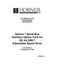
Introduction to Genius
Genius is a high-speed token passing network which has been used in industrial applications for many
years. The network supports up to 32 devices, with baud rates of up to 153.6kbaud. A wide variety of
Genius devices exist which can reside on the network, ranging from intelligent I/O blocks to more
sophisticated communications devices such as personal computers. In recent years a number of third
party devices have emerged, including Operator Interface Units, valve manifolds, RF tag readers, etc.
In a typical industrial application, Genius devices are distributed throughout a fairly wide area, wired in a
daisy chained fashion with a single shielded, twisted pair. The Serial Bus Interface Genius option card
allows the AV300/DV300 Drives to be distributed on the factory floor on the same twisted pair as the I/O
blocks and other Genius devices. This provides a new level of PLC integration for the drives. The
physical nature of the network can allow for great savings in wiring, as many discrete wires can be
replaced with a single communications cable. This allows tasks such as starting, stopping, reversing, and
changing speeds to be accomplished over the LAN. In addition, drive parameters and diagnostic data
previously not available to the PLC are easily accessible.
Figure 4.1 - Typical Genius Devices and Architecture
4.2
Network Architecture
Normally, a GE Fanuc programmable controller runs the network, through a PLC module called a Genius
Bus Controller (GBC). Devices (up to 32 in number) are wired in a daisy-chained fashion. Network
devices support four communications terminals, Serial 1, Serial 2, Shield In and Shield Out. The network
is terminated at each end with an appropriate terminating resistor. The value of the resistor should be
chosen to match the characteristic impedance of the cable. Refer to GE Fanuc Automation publication
PAGE 24
CH. 4
05 DEC 2000
MAN0018-03
GFK-90486 for help in selecting an appropriate cable type for your application. Note: If the characteristic
impedance of the cable is unknown, 120 ohm terminating resistors should be used.
Each of the (up to) 32 devices on the network is assigned a Genius Bus Address ranging from 0 to 31.
Bus Controllers are most typically assigned a Genius Bus Address of 31. In applications with redundant
bus controllers, the “backup” bus controller is address 30. Bus address 0 is normally reserved for the
Genius Hand Held Monitor.
Among other tasks, the bus controller allows Genius I/O (including the drives) on the network to be
mapped into PLC memory, monitoring inputs and controlling outputs. Intelligent, data intensive Genius
devices also share their data with the PLC through communications with the bus controller.
4.3
Genius Communications Services
As stated previously, the Serial Bus Interface Genius option card allows the drive to reside directly on the
Genius LAN, providing drive control and data access capabilities to the PLC. There are three types of
communications that can occur on the Genius LAN. These are I/O Services, Global Data and
Datagrams. The Serial Bus Interface option card supports all three of these communications types.
4.4
I/O Service
I/O Service is the manner in which data is transferred to and from Genius I/O Blocks. Outputs are
selectively written to each I/O block from the CPU bus controller each scan. Many I/O blocks also
broadcast inputs to the bus every bus scan.
4.5
Global Data
Global data is data broadcast over the network at large, with no particular “destination”. Each Genius
device has the capacity to broadcast up to 128 bytes of global data. Intelligent devices which reside on
the LAN (bus controllers, OIUs, etc.) can read this data off the network. These devices are intelligent
enough to interpret this data, as the data content differs from Genius device to Genius device. Drive
feedback data consists of parameters such as speed reference, torque, current, faults, function settings,
etc. The Serial Bus interface allows the system designer to select which data is broadcast by the drive as
global data. This is important for two reasons. First of all, the data which is desired to be monitored on a
regular basis varies from application to application. Second, the amount of global data broadcast by the
drive is directly proportional to response time.
In general, the procedure for configuring the drive’s Global output data is a process of mapping the global
output data words to drive parameters. There are three different means in which this “mapping” of global
data output words to drive parameters can be accomplished. These are; from the keypad, from the
Genius Hand Held Monitor, and from the optional personal computer configuration utility. Chapters are
dedicated to each of these configuration means.
4.6
Datagrams
Datagrams are messages sent over the Genius LAN from one device to another. Datagrams are typically
performed in PLC applications through a communications request, or COMREQ. Typically, COMREQs
are used for occasional data access. For instance, COMREQs would typically not be used to monitor
speed reference on a continuous basis, but might be used to change a drive parameter once a shift or
once a week. Datagrams (through COMREQs) could also be used to upload or download all drive
parameters over the network. In PLC applications, a bus controller is required to perform datagrams or
COMREQs.
MAN0018-03
05 DEC 2000
PAGE 25
CH. 5
CHAPTER 5: PLC CONFIGURATION
5.1
PLC Configuration
This chapter discusses the configuration of the PLC in Genius applications using the AV-300/DV-300
drives with the Serial Bus Interface option board. As mentioned in a previous chapter, Genius LANs
performing control require a Genius Bus Controller. Most GE Fanuc PLCs offer a module which acts as
the bus controller. This document discusses configuration of the Series 90 PLCs -- Series 90-30 and
Series 90-70.
5.2
Series 90-70 Configuration
For successful integration of the Series 90-70 GBC, the document GFK-0398, Series 90-70 Genius Bus
Controller User's Manual is required.
Configuration of Series 90-70 PLC system requires the use of Logicmaster 90-70, the personal computer
software package used for ladder logic programming and system setup. Configuration of the Genius
devices residing on the LAN with Logicmaster 90-70 cannot be accomplished until the Genius Bus
Controller (GBC) is configured. For instructions on that process, consult GFK-0398 from GE Fanuc.
After configuration of the GBC has been completed, the Genius devices residing on the LAN may be
configured by zooming into the slot containing the GBC. A Logicmaster screen similar to that below will
appear:
Figure 5.1 - Logicmaster 90-70 Configuration Screen
This is a representation of the Genius LAN, with each device shown as a "block". Because only eight
devices can be shown on the screen at once, the screen "wraps around" from left to right. The left and
right cursor keys are used to select the device to be configured. When the desired block is highlighted,
the type of Genius device can be selected using the function keys. The SBI is configured as a "Generic
Genius I/O Device". This device is selected by pressing the "Other" (F7) function key, and selecting the
"Generic I/O" device from the devices listed.
PAGE 26
CH. 5
05 DEC 2000
MAN0018-03
Figure 5.2 - Generic I/O device Configuration Screen
Below, each configuration parameter is described. The proper setting for a drive with a default data
configuration is also listed. Figure 5.3 on the next page lists the default drive data configuration.
5.2.1
%I Length
(Default = 16)
The number of %I's assigned to the drive should be equal to 16 times the number of bit-mapped global
data words broadcast by the drive. Bit mapped parameters should be mapped first in the SBI and defined
using %Is in the PLC configuration.
5.2.2
%Q Length
(Default = 16)
The number of %Qs assigned to the drive should be 16 times the number of bit-mapped directed control
words (directed data). Bit mapped parameters should be mapped first in the drive and defined using
%Qs in the PLC configuration.
5.2.3
%AI Length
(Default = 6)
The number of %AIs assigned to the drive should be equal to the number of non-bitmapped global data
words broadcast by the drive.
5.2.4
%AQ Length
(Default = 1)
The number of %AQs assigned to the drive should be equal to the number of non-bitmapped directed
control words.
5.2.5
Reference Addresses
In addition to the length of each of the four I/O references (%I, %Q, %AI, %AQ), the starting reference
address for each I/O type must be set for each of the I/O references with a non-zero length. This
reference address should not conflict with any other I/O module or Genius device.
MAN0018-03
5.2.6
05 DEC 2000
PAGE 27
CH. 5
Redundancy
If the AV-300/DV-300 is used in a redundant application, this parameter should be set to YES.
5.2.7
Input Default
The input defaults can be set to OFF or HOLD, as desired.
5.2.8
Outputs Enabled
If outputs from the PLC are to be enabled (most cases), this parameter should be set to YES.
Note that the reference types available for mapping into Series 90-30 memory are more numerous
than those available for the Series 90-70. This is due to the fact that the Series 90-70 performs
more data type checking than the Series 90-30. This extra checking requires that the number and
type of memory references match exactly in the Series 90-70. The Series 90-30 requires only that
the amount of data match exactly.
5.3
Series 90-30 Configuration
For full information on the configuration of Genius LANs with the Series 90-30 PLC, consult the GE Fanuc
document GFK-1034, Series 90-30 Genius Bus Controller User's Manual.
The Series 90-30 PLC is configured using Logicmaster 90-30. In the configuration package, the Genius
Bus Controller (GBC) configuration screen appears as follows:
Figure 5.3 - Series 90-30 GBC Configuration Screen
PAGE 28
CH. 5
05 DEC 2000
MAN0018-03
The devices residing on the Genius LAN are configured in the lower "Device Data" section of the screen.
The cursor keys are used to navigate around the screen. When the cursor is on the "Device Data"
section of the screen, the PageUp and PageDown keys are used to select the Device number. Once the
proper device number is displayed for the AV-300/DV-300, the following parameters can be set.
5.3.1
Device Type
The AV-300/DV-300 is configured as a GENERIC device type, which is the default.
5.3.2
Input References (Input 1 Ref, Input 2 Ref)
These parameters specify where the SBI’s global data is mapped in Series 90-30 memory. Legal
reference types for these parameters are %I, %G, %AI, and %R. As you can see, the global data
broadcast by the SBI can be divided into two different areas of PLC memory. For instance, part of the
global data could be mapped into %I, and the remainder into %AI. Two non-consecutive areas of the
same reference type could also be mapped. For instance, part of the global data could be mapped to
%R1, and the remainder to %R500.
5.3.3
Input Length (Input 1 Len, Input 2 Len)
These parameters specify how much global data is broadcast by the SBI. If the Input Reference specified
is bit-type (%I, %G), the length parameter is in bits. If the Input Reference specified is word type (%AI,
%R), the length parameter is in words. The total amount of data mapped into the Series 90-30 must
exactly match the total amount of global data broadcast by the SBI.
5.3.4
Output References (Output 1 Ref, Output 2 Ref)
These parameters specify where the AV-300/DV-300 directed control data is mapped in Series 90-30
memory. Legal reference types for these parameters are %Q, %G, %AQ, and %R. As you can see, the
directed data input by the SBI can be divided into two different areas of PLC memory. For instance, part
of the global data could be mapped into %Q, and the remainder into %AQ. Two non-consecutive areas
of the same reference type could also be mapped. For instance, part of the directed data could be
mapped to %R1, and the remainder to %R500.
5.3.5
Output Length (Output 1 Len, Output 2 Len)
These parameters specify how much directed data is received by the SBI. If the Output Reference
specified is bit-type (%Q, %G), the length parameter is in bits. If the Output Reference specified is word
type (%AQ, %R), the length parameter is in words. The total amount of data mapped from the Series 9030 must exactly match the total amount of global data received by the SBI.
MAN0018-03
05 DEC 2000
PAGE 29
CH. 6
CHAPTER 6: AV-300 / DV-300 DRIVE PARAMETERS
6.1
Drive Parameter Descriptions
The parameters and parameter numbers associated with the AV-300 and DV-300 adjustable speed
drives are listed as “Pick Lists” in the software configuration tool, and can be accessed with the hand held
monitor attached to the drive. For further information on these parameters, consult the AV-300/DV-300
instruction manuals.
Due to constant revisions to the parameters, the parameter information will not be contained in
this manual. The information can be obtained from the AV-300/DV-300 Instructions Manual.
The following sections explain how the AV-300 and DV-300 Manual Parameter Table relates to the
Software Configuration Tool Pick Lists.
6.2
DIRECTION:
The parameter table contains "R", "W", "Z" and "C" symbols to designate read and write parameters. A
“R” represents a read from the drive to the master. This relates to the Edit Global Data configuration
option in the software configuration tool. A “W”, “Z” or “C” represents a write from the master to the drive.
This relates to the Edit Directed Control Data configuration option in the software configuration tool.
6.3
ACCESS METHOD:
The access method is selected under SOURCE while configuring Global Data or Directed Control Data.
The options discussed below are Low Priority To/From Drive, High Priority To/From Drive, Low Priority
Discrete Bit Word To/From Drive and High Priority Discrete Bit Word To/From Drive.
The following shows the columns needed to determine the available SOURCE options available for a
given parameter and a description on how the columns are used.
6.4
LOW PRIORITY TO/FROM DRIVE:
RS485/BUS/Opt2-M - A read or write in this column designates that the parameter can be accessed
using the Low Priority To/From Drive option.
6.5
HIGH PRIORITY TO/FROM DRIVE: *
MINIMUM, MAXIMUM, Opt2-A/PDC - A read or write in Opt2-A/PDC and a minimum value not equal to 0
or a maximum value greater than 1 designates that the parameter can be accessed using the High
Priority To/From Drive option.
6.6
LOW PRIORITY DISCRETE BIT WORD TO/FROM DRIVE:
MINIMUM, MAXIMUM. Opt2-A/PDC - A minimum value of 0 and a maximum value of 1. All High Priority
Discrete Bit Words qualify for Low Priority Discrete Bit Words.
6.7
HIGH PRIORITY DISCRETE BIT WORD TO/FROM DRIVE: *
MINIMUM, MAXIMUM, Opt2-A/PDC - A minimum value of 0 and a maximum value of 1 and a read or
write in Opt2-A/PDC column.
*NOTE: The High Priority To/From Drive and the High Priority Discrete Bit Word To/From Drive are
mutually exclusive. A parameter is either eligible for High Priority access or High Priority Discrete
Bit Word access, not both.
PAGE 30
CH. 6
05 DEC 2000
NOTES
MAN0018-03
MAN0018-03
05 DEC 2000
PAGE 31
CH. 7
CHAPTER 7: WIRING DIAGRAMS
7.1
Genius Wiring:
R S 232
Figure 7.1 - Typical Genius Wiring Diagram
S e ria l B u s In te r fa c e
G e n iu s C o n n e c to r
S h ie ld
o u t
G E N IU S
S h ie ld
In
S e r ia l 2
R S 485
S e r ia l 1
Figure 7.2. Serial Bus Interface Genius Connector
Note: Shield Out is connected to the metal shell and jack screws of J1 and J2. Earth ground can
be connected at any of these locations. Earth Ground must be connected!
For further instruction on wiring, consult the GE Fanuc User’s Manual GEK-90486f-1 (Genius I/O Systems
and Communications).
PAGE 32
CH. 7
7.2
05 DEC 2000
RS232/RS485 Pinout:
2 Txd Out
7 Cts In
3 Rxd In
8 Rts Out
5 Gnd
Figurer 7.3 - RS232 - J1
3A
7B
5 Gnd
Figure 7.3 - Two-Wire RS485 - J2
(Operates in Half-Duplex Mode)
The following jumpers are associated with RS485 (J2).
a)
b)
JP2 - Jumper on places a 120 Ohm terminating resistor on the circuit. (See 8.3.8.)
JP10 - Places 5volts at J2 Pin9. (See 8.3.9.)
For more information on the hardware setup, see the GECFG Help file.
MAN0018-03
MAN0018-03
05 DEC 2000
PAGE 33
CH. 8
CHAPTER 8: INSTALLING THE SBI CARD
8.1
Installation Hardware
Included in the packaging with the SBI option card are the following:
a. The option card.
b. One installation kit. (consisting of four metal standoffs, four Phillips head screws, four lock-washers,
and one 3” 40 pin ribbon cable)
c. This Document.
8.2 Required Tools
The following tools are required to install the SBI option card.
a. Philips Screwdriver.
b. Flat tip Screwdriver.
c. 5/32’s Nut-driver.
8.3
The installation procedures.
The SBI option card is installed inside the drive cover, so that the NEMA rating of the drive is maintained
after installation of the option card.
a. Power down the drive.
b. Remove the cover from the drive.
Figure 8.1 - Removing the Front panel
PAGE 34
CH. 8
05 DEC 2000
MAN0018-03
The front cover is divided into two parts. First remove the lower section by unscrewing the two Phillips
screws (Marked A’ on Figure 8.1) just enough for the section to separate from the upper section. Lift
lower section up while pulling down at the same time. Remove the top section by lifting up on the back
until the pins slide over the holes (on the top of the drive), then disconnect the ribbon cable attached to
the keypad.
c. Install the four metal standoffs.
Using a 5/32’s nut driver, screw the standoffs into holes marked “A” (see Figure 8.2).
Figure 8.2 – Installing Metal Standoffs
d. Place the SBI board on the standoffs
Align the holes marked “B” with the top of the standoffs (see Figure 8.3). Attach using the four screws
with lock washers. Make sure the connectors on the SBI card are pointing at the same end as the
connectors on the drive board.
e. Insert one end of the 40-pin ribbon cable into the connector on the SBI card (P3), and the other end
into the connector on the drive (marked XO). The red ribbon (symbolizing pin 1) should be facing the
back of the board.
f. Set the jumpers (JP1, JP2, and JP10) on the SBI option card.
MAN0018-03
05 DEC 2000
PAGE 35
CH. 8
1. JP1: RS-232/485 port select
Jumper on, RS-232 port selected, jumper off, RS-485 port selected. This jumper determines which port is
used for sending/receiving configuration information, The state of the jumper is only checked at power up.
2. JP2: Termination Resistor
Jumper on, 120 ohm resistor, jumper off, no termination. This jumper allows a 120 ohm terminating
resistor to be connected between data +(A) and –(B).
P ow er
B
B
Reset
COM M OK
G E NA O K
Transm it
Receive
G E NIUS
B
RS 485
RS 232
B
Figure 8.3 – Placing the SBI Board on Metal Standoffs
3. JP10
RS-485 power: Jumper on, +5volts out, Jumper off, no +5volts out. This jumper allows power to be
supplied to the RS-485 connector to power RS-485 converters. Set jumper for no power.
PAGE 36
CH. 8
05 DEC 2000
MAN0018-03
8.4
Grounding the AV/DV 300 GE Drive Genius SBI Option Card
8.4.1
Installation
For installations where noise is a problem, it is necessary to connect a grounding wire to the Genius
Serial Bus Interface card. Since no part of the Interface board physically makes contact to the drive, an
external ground between the jacketing screw on the RS-485 port and the panel ground is necessary. The
following instructions on the next page give a detailed representation of how to do this. A ground wire is
included with the SBI card.
a. If Possible, Disconnect power to the AV/DV drive.
b. Remove the cover panel from the AV/DV drive (for instructions on how to do so consult Chapter 8 in
the manual).
c. Using a 5/16 nut driver loosen the jack screw labeled “A” in Figure 8.4 enough to be able to slide the
terminal connector onto the stud between the nut and the jacket of the RS485 connector.
d. Place the terminal lug between the jacket and the jack screw head. Secure the lug firmly by tightening
the jack screw head.
G E N IU S
R S 4 8 5
R S 2 3 2
A
A
Figure 8.4 – Jack Screw
e. Route the grounding wire along the front of the drive and connect the stripped end to the panel
mounting screw marked “B” on Figure 8.5.
B
Figure 8.5 – Panel Mounting Screw
MAN0018-03
05 DEC 2000
PAGE 37
CH. 8
f. After configuring the SBI option card with the software configuration tool, and connecting the Genius
cable to P1, replace the front cover.
The drive is now ready to be operated with the SBI option card.
PAGE 38
CH. 8
05 DEC 2000
NOTES
MAN0018-03
MAN0018-03
05 DEC 2000
PAGE 39
CH. 9
CHAPTER 9: SBI CARD LED INDICATORS
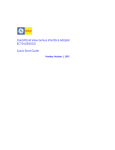
The SBI card has six LED indicators for general troubleshooting. See figure 9.1 for the location of the
LED’s (next page).
9.1
“Power” Indicator
The “Power” indicator informs the user that the SBI card is getting power. If the Drive is powered up, and
this light is not illuminated, insure the ribbon cable is properly connected.
9.2
“Reset” Indicator
The “reset” indicator will be illuminated as long as the power light is illuminated. If the SBI card appears
to be having problems, and the reset LED is not illuminated, contact Horner APG’s Technical Support.
9.3
“Transmit” Indicator
The “Transmit” indicator will flash when data is transmitted to a PC while reading the configuration from
the SBI card with the software configuration tool.
9.4
“Receive” Indicator
The “Receive” indicator will flash when data is received while writing a configuration to the SBI using the
software configuration tool.
9.5
“GENA OK” Indicator
The “GENA OK” indicator will be illuminated unless there is a fault with the GENA board.
9.6
“COMM OK” Indicator
The “COMM OK” indicator illuminates when the GENA board is communicating with the GBC properly. If
the “COMM OK” LED is not illuminated after configuration, check the following:
Make sure the SBI configuration Global Data and Directed data length matches the Summary Global
Data words, and the Directed Control Data words (In the software configuration tool).
Make sure the Cable is wired correctly between the GBC and the SBI card.
Check the GBC configuration (LM90 Configuration package). The Global data length, and the Directed
control data length must match the input length and the output length respectively.
PAGE 40
CH. 9
05 DEC 2000
LED “A”:
LED “B”:
LED “C”:
LED “D”:
LED “E”:
LED “F”:
Power indicator.
Reset Indicator.
Transmit Indicator.
Receive Indicator.
GENA OK Indicator.
Communication OK.
$
%
MAN0018-03
Reset
(
)
&
'
GENIUS
RS485
RS232
Figure 9.1 - Serial Bus Interface LED description, and nomenclature
MAN0018-03
05 DEC 2000
PAGE 41
APPENDIX A
APPENDIX A: HE300GEN200 ECHO TEST TIMING RESULTS
A.1
Test Setup:
Equipment:
1 Dual PCIM in a Pentium 200
1 AV-300/Dv-300 Drive
1 Genius SBI w/ V1.10 Firmware
A.2
Setup
PCIM is installed in computer and configured.
PCIM connected to Genius SBI via Genius cable.
Computer serial port connected to SBI serial port for configuration changes using the Software
configuration tool.
A.3
General Procedure
The SBI is configured as described in the different sections. The Gena configuration is also described in
the different sections. GENIUS.EXE program is run. F1 is pressed to start the test. The test program
writes a value to the drive over Genius then times how long it takes to receive the same value back.
There are 999 different values sent and timed. The average time, maximum time and minimum time are
displayed as the test is running. The timing results are displayed in milliseconds. A time of 0 is a time of
less than 1ms.
A.4
HIGH PRIORITY I/O TEST
Software Configuration Tool Settings: 1 High Priority DCD to Pad 0, 1 High Priority Global from Pad 0
Genius Configuration: 1 IN/1 OUT
Attempt
1
2
Average Time
35.40
35.07
Max Time
55
55
Min Time
0 (< 1ms)
1
Software Configuration Tool Settings: 1 High Priority DCD to Pad 0, 1 High Priority Global from Pad 0
Genius Configuration: 5 IN/5 OUT
Attempt
1
2
Average Time
35.95
35.42
Max Time
54
55
Min Time
0
0
Software Configuration Tool Settings: 5 High Priority DCD to Pad 0 through Pad 4, 5 High Priority Global
from Pad 0 through Pad 4. Genius Configuration: 5 IN/5 OUT
Attempt
1
2
Average Time
34.51
33.60
Max Time
55
55
Min Time
0
0
PAGE 42
APPENDIX A
A.5
05 DEC 2000
MAN0018-03
LOW PRIORITY I/O TEST:
Software Configuration Tool Settings: 1 Low Priority DCD to Pad 0, 1 Low Priority Global from Pad 0
Genius Configuration: 1 IN/1 OUT
Attempt
1
2
Average Time
98.30
98.12
Max Time
165
165
Min Time
79
76
Software Configuration Tool Settings: 1 Low Priority DCD to Pad 0, 1 Low Priority Global from Pad 0
Genius Configuration: 5 IN/5 OUT
Attempt
1
2
Average Time
98.03
98.84
Max Time
165
165
Min Time
78
79
Software Configuration Tool Settings: 5 Low Priority DCD to Pad 0 through Pad 4, 5 Low Priority Global
from Pad 0 through Pad 4. Genius Configuration: 5 IN/5 OUT
Attempt
1
2
A.6
Average Time
204.85
204.39
Max Time
275
275
Min Time
165
131
DGFC I/O TEST:
This test used a program already in the DGFC that copies Pad 0 to Pad 3. The value was sent out of the
PCIM over Genius to the SBI. The SBI detected a data change and wrote the value to Pad 0 in the drive.
The DGFC then copied the value from Pad 0 to Pad 3. The SBI was configured to read Pad 3, so it was
reading Pad 3 every time through its internal scan and storing the result in the Gena memory.
The following diagram shows the data path:
Write
Read
Æ
Å
PCIM
A.7
Detect
Æ
Å
SBI
Pad 0
Pad 3
DRIVE
Æ
Å
Copy
DGFC
High Priority Test
Software Configuration tool Settings: 1 High Priority DCD to Pad 0, 1 High Priority Global from Pad 3
Genius Configuration: 2 IN/2 OUT
Attempt
1
2
Average Time
26.34
26.61
Max Time
55
55
Min Time
0
0
MAN0018-03
A.8
05 DEC 2000
PAGE 43
APPENDIX A
Low Priority Test
Software Configuration Tool Settings: 1 Low Priority DCD to Pad 0, 1 Low Priority Global from Pad 3
Genius Configuration: 2 IN/2 OUT
Attempt
1
2
A.9
Average Time
99.06
98.57
Max Time
165
165
Min Time
78
79
OLD VS NEW (Version 1.09 VS Version 1.10)
The same configuration was used for all of the testing in this section. The configuration is as follows:
Software Configuration Tool Settings: 1 High Priority DCD to Pad 0
1 Low Priority DCD to Pad 1
1 High Priority Global from Pad 0
1 Low Priority Global from Pad 1
Genius Configuration: 2 IN/2 OUT
OLD VERSION (1.09) HIGH PRIORITY:
Attempt
1
2
Average Time
60.72
59.18
Max Time
118
110
Min Time
78
45
OLD VERSION (1.09) LOW PRIORITY:
Attempt
1
2
Average Time
115.53
114.85
Max Time
218
217
Min Time
-----55
NEW VERSION (1.10) HIGH PRIORITY:
Attempt
1
2
Average Time
32.82
32.89
Max Time
55
54
Min Time
0
0
NEW VERSION (1.10) LOW PRIORITY:
Attempt
1
2
A.10
Average Time
105.37
106.68
Max Time
165
165
Min Time
64
71
Genius SBI Internal Timing Result:
Test code was inserted into the Genius SBI firmware. There were 2 parts to the test code. The first part
of the test code detected when a new value was in Gena memory and cleared a port pin. The value was
then written to the drive as usual. The second part detected when the same value was read back from
the drive and set the port pin. This allowed for a scope to be used to determine how long it tool the SBI to
detect a data change, write the value to the drive, receive the value back from the drive and write it to the
Gena memory. The same GENIUS.EXE program and test was used as above. The scope was used to
determine maximum and minimum SBI internal timing.
A.11
High Priority Timing
Software Configuration Tool Settings: 1 High Priority DCD to Pad 0, 1 High Priority Global from Pad 0
Genius Configuration: 1 IN/1 OUT
Result: 2.5 to 25ms
PAGE 44
APPENDIX A
A.12
05 DEC 2000
MAN0018-03
Low Priority Timing:
Configuration Tool Settings: 1 Low Priority DCD to Pad 0, 1 Low Priority Global from Pad 0
Genius Configuration: 1 IN/1 OUT
Result: 80 to 90 ms (This can vary depending on which parameter is being accessed and time it takes
the drive to access that parameter.)
MAN0018-03
05 DEC 2000
PAGE 45
APPENDIX B: TECHNICAL SUPPORT
For any questions or problems not addressed by this manual, contact Horner APG’s Technical Support at
317-916-4274, or drop an e-mail to [email protected].
For further information on Horner APG products, go to our web site located at HTTP://www.heapg.com.
The web site has a technical support area, as well as a product catalog. If a manual is needed for a
certain product, the manual can be downloaded in PDF format using Acrobat from the web site.
PAGE 46
05 DEC 2000
NOTES
MAN0018-03
MAN0018-03
05 DEC 2000
PAGE 47
INDEX
INDEX
%AI Length, 26
%AQ Length, 26
%I Length, 26
%Q Length, 26
“COMM OK” Indicator, 39
“GENA OK” Indicator, 39
“Power” Indicator, 39
“Receive” Indicator, 39
“Reset” Indicator, 39
“Transmit” Indicator, 39
ACCESS METHOD:, 29
Automatic Data Transfer, 13
Datagrams, 15, 24
Device Type, 28
DGFC I/O TEST, 42
DIRECTION:, 29
Drive Parameter Descriptions, 29
General Procedure, 41
Genius Communications Services, 24
Genius SBI Internal Timing Result, 43
Genius SBI Operation, 13
Genius Wiring, 31
Global Data, 24
Grounding the AV/DV 300 GE Drive Genius SBI
Option Card, 36
HIGH PRIORITY DISCRETE BIT WORD
TO/FROM DRIVE: *, 29
HIGH PRIORITY I/O TEST, 41
High Priority Test, 42
High Priority Timing, 43
HIGH PRIORITY TO/FROM DRIVE: *, 29
I/O Service, 24
Input Default, 27
Input Length (Input 1 Len, Input 2 Len, 28
Input References (Input 1 Ref, Input 2 Ref), 28
Installation, 36
Installation Hardware, 33
Introduction to Genius, 23
LOW PRIORITY DISCRETE BIT WORD
TO/FROM DRIVE:, 29
LOW PRIORITY I/O TEST, 42
Low Priority Test, 43
Low Priority Timing, 44
LOW PRIORITY TO/FROM DRIVE:, 29
Miscellaneous Information About Datagrams, 21
Network Architecture, 23
OLD VS NEW (Version 1.09 VS Version 1.10),
43
Output Length (Output 1 Len, Output 2 Len), 28
Output References (Output 1 Ref, Output 2 Ref),
28
Outputs Enabled, 27
PLC Configuration, 25
Random Read Device, 20
Random Write Device, 19
Read Device (1EH) Datagram Header Format,
16
Read Device Reply, 20
Redundancy, 27
Reference Addresses, 26
Required Tools, 33
RS232/RS485 Pinout, 32
SBI Access Methods, 11
SBI, Global Data, 14
Sequential Read Device, 19
Sequential Write Device, 18
Series 90-30 Configuration, 27
Series 90-70 Configuration, 25
Setup, 41
Specific Operations, 17
technical support, 45
Test Setup, 41
The installation procedures, 33
PAGE 48
INDEX
05 DEC 2000
NOTES
MAN0018-03