1
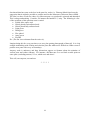
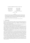
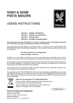
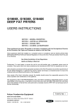
INDEX
Spring . . . . . . . . . . . . . . . . . . . . . . . . . . . . 1
Minutes of meeting of 21 st January . . . . . . . . . . . . . 1
Minutes of meeting of 18th March . . . . . . . . . . . . . . 2
Meccano Street Racing Car Set Review . . . . . . . . . . . 4
An Unusual Request . . . . . . . . . . . . . . . . . . . . . 6
MotorVator – A Review . . . . . . . . . . . . . . . . . . . 8
The Menstrie Challenge . . . . . . . . . . . . . . . . . . . 12
Among the Model Builders . . . . . . . . . . . . . . . . . 13
Meccano on the Internet . . . . . . . . . . . . . . . . . . 16
DATES FOR YOUR DIARY
Balado . . . . . . . . . . . . . . . . . . . . . . . . . . . . . . . .
12th/13th May
Constructor’s Day . . . . . . . . . . . . . . . . . . . . . . . . . . . 19th May
NEMS Exhibition at Shildon . . . . . . . . . . . . . . . . . . . . . 27th/28th May
SkegEx . . . . . . . . . . . . . . . . . . . . . . . . . . . . . . . . 29th June/1stJuly
Society meeting, Smith’s Museum, Stirling . . . . . . . . . . . . . 19th August
Annual Exhibition, Scone . . . . . . . . . . . . . . . . . . . . . . 8th/9th September
Society meeting, Smith’s Museum, Stirling . . . . . . . . . . . . . 18th November
SPRING
No, not tension or compression, the green shoots kind. Yes, it is here again and the gardening
tools have to come out and outdoor pursuits of a more frivolous nature take over as the clock
changes and the weather gets a little warmer. For Meccanomen (and ladies, one hastens to add –
our female membership having tripled in the past year) the winter pastime of model building
may well have to take a back seat as the season changes. However we do have a series of events
to look forward to. The exhibition at Balado and the Menstrie Constructors Day are now only a
few weeks away. Members are encouraged to do a small amount of (inventive?) model building
for the latter – see The Menstrie Challenge later in this issue.
This issue of the newsletter is atypical in that it contains no exhibition reports. This is a
reflection of the time of year – all exhibitions that we attend are in the May – November period.
What we do have are a series of articles by members of the Society either reviewing Meccano
products or outlining solutions to various problems encountered when model building. The
article in this latter vein will be, we hope, the first of an occasional series in the style of the
“Among the Model Builders” series that used to appear in the Meccano Magazine. What we
will need to make this a success is as many members as possible to write articles under this
heading. They do not have to be long, pictures attached would be welcome but not necessary.
Whatever you have built recently and whatever you build from now on, take note of the
difficulties involved, document them, however briefly, along with an account of your way out of
the problem and send the result to the editor. It would also be good to hear from people who do
not encounter any problems. Their considerable expertise deserves a wider audience.
* * * * *
Club Meeting, 21 January 2007
The meeting was held as usual in the Smith Art Gallery and Museum, Stirling, at 2 pm.
Members present were Jim Berrie, Philip Hore, Margaret Tattersfield, Angus Plumb, Douglas
Carson, Bill Jack, Jim Wood, Gordon MacMillan, Dick Martin, Bob Middlemass, Mike Ridley,
Jackie Inglis, Jim Gregory, Desmond Smith, Alan McDonald (Treasurer), Alan Blair, Alistair
Nicoll (Newsletter Editor), Tim Edwards (Webmaster), and Bert Hutchings (Secretary). There
were apologies from Martin Donoghue.
Exhibitions: the Scottish Traction Engine Society has invited us to exhibit at Balado again this
year, on 12 and 13 May. A sufficient number of members agreed that they would attend on the
Saturday, the Sunday, or both days (Alan McDonald, Jim Berrie, Jackie Inglis, Alan Blair,
Margaret Tattersfield, Douglas Carson, Dick Martin, and Bert Hutchings).
We also look forward to our annual exhibition at Scone on 8 and 9 September, in conjunction
with the “Farming Yesteryear” event of the Scottish Vintage Tractor and Engine Club, which
Alan Blair is attending to the details of. He suggested that small models could be arranged on
shelving to peciali the use of the available space, and urged members to contribute to this. For
publicity, the Treasurer and Angus Plumb agreed to explore various ways of producing
laminated copies of traditional Meccano posters and advertisements, up to A2 size if possible.
Alistair Nicoll and Tim Edwards had collaborated on the rules for the competition at our Open
1
Day at Menstrie on 19 May. The rules were distributed and agreed.
Treasurer: the Treasurer reported that 4 of last year’s members had not yet renewed their
subscriptions, and that we had one new member, introduced by Jim Gregory.
Newsletter: the Editor suggested the inclusion of a section similar to the “Among the ModelBuilders” feature found in older Meccano Magazines. The meeting was enthusiastic, although
the feature will depend on contributions from members, and especially from competition
winners.
Website: the Webmaster had recently corrected the model builders’ names relating to last year’s
Open Day, and also updated the site with pictures from Scone.
Other business: the Secretary passed round an incomplete 1922 sawbench for members’
interest, since it is a relatively scarce item. Philip Hore had examples of the recent Marks and
Spencer “Red Arrow” and “Vintage 1933” sets, which were interesting items but everybody
agreed that the lack of any continuity in the range of these new sets still seemed like an
unfortunate backward step. Jim Gregory showed us two small models of his own, and Jim
Wood had two more built from the new sets. These were advertised as suitable for 8 years old
and over, but Jim said that they had been quite tricky to assemble, although the Allen-head bolts
helped quite a bit. Doug Carson had contributed to a friend’s fancy dress outfit with a watch,
chain and fob all made from Meccano parts which were much admired. Gordon MacMillan
showed us an East German “Eitech” construction set resembling Meccano in some respects but
with the parts in metric sizes. Desmond Smith brought along a set from the new “Speed Play”
range, and members were very interested in its combination of many new pecialized parts with
a fair quantity of the traditional older parts. Mike Ridley had acquired a number of parts which
he thought were Erector, and members familiar with the range confirmed this for him.
Bert Hutchings, Secretary
* * * * *
Club Meeting, 18 March 2007
The meeting was held as usual in the Smith Art Gallery and Museum, Stirling, at 2 pm.
Members present were Alan McDonald (Treasurer), Margaret Tattersfield, Angela Goodlet (new
member), Desmond Smith, Jim Gregory, Jackie Inglis, Bill Jack, Douglas Carson, Angus
Plumb, Dick Martin, Jim Berrie, Ken McDonald, Tim Edwards (Webmaster), and Bert
Hutchings (Secretary). There were apologies from Gordon Macmillan.
Exhibitions: the members exhibiting at Balado on 12-13 May all confirmed their plans to
attend, and Ken McDonald offered to stand in for anybody who had to drop out. The Treasurer
will arrange to have the banner brought on the Saturday, and the Secretary will bring some of
our table covers. The North Midlands Meccano Guild’s annual exhibition at Skegness is on 2930 June and 1 July. Jim Gregory will host another exhibition at Auchterarder on 28 July, to
raise funds for the “Amazon Hope” travelling health centre, and all members are welcome.
2
In Alan Blair’s absence, it was hoped that all the arrangements for Scone on 8-9 September were
progressing well. Jim Berrie had brought a very large poster which Angus Plumb took away,
expecting to be able to reproduce and laminate it, and the meeting agreed to the probable cost.
He also selected a few smaller posters from a group which Tim Edwards had brought. Our
thanks to all these members for this effort.
Treasurer: the Treasurer reported that our insurance agent had been taken over, and the new
larger owners had declined to continue our cover. Several members were quite concerned about
any potential public liability claim. The Secretary will inquire about other clubs’ arrangements.
Website: further competition pictures have been added. A few members suggested that there
could be a section on the web site where visitors could record their comments about it, and the
Webmaster agreed to investigate this.
Other business: Angela Goodlet displayed a colourful catamaran, and a giant swingboat, both
built mostly from the parts in the Ferris Wheel set. She hopes to add lighting to the swingboat.
Jackie Inglis was able to warn members that the small single-model sets available in some
branches of Boots were the same as the Marks and Spencer sets, but considerably dearer.
Douglas Carson showed us a single-cylinder stationary engine made with parts from a wide
range of periods, which he had bought very cheaply on eBay and completed by adding a small
motor and sprocket drive.
Future meetings: Open Day at Menstrie on 19 May, then 19 August and 18 November, both at
Stirling.
Bert Hutchings, Secretary
* * * * *
3
THE MECCANO STREET RACING RC CAR
SET REVIEW
by
Douglas Carson
Urban RC
Street Racing Car
Touring Style RC
The Meccano Street Racing RC (8950) car is one of three in the 2006 catalogue which
collectively form the Tuning range of models. The others are the Urban RC (6950) and the
Touring Style RC (8951). The three models are illustrated above. I was fortunate enough to
receive my model for Christmas, so later that evening I retreated from the festivities to the
model room to begin construction. The kit is well packaged in polystyrene inside a cardboard
box and comprises 368 parts. Three different models can be built (one at a time) and I opted for
the one illustrated above.
The most significant part is the chassis which comes as a single part comprising chassis, wheels,
front wheel steering, remote control (RC) receiver, servos and batteries, all (except the wheels)
encased in black plastic. Accompanying this is the RC transmitter which is also illustrated
above. The chassis is powered by six 1.5V batteries and the RC unit takes one 9V battery. The
remote control operates on 27 MHz and only one frequency is provided so it is impossible to
operated more than one vehicle in close proximity.
I would have found it more enjoyable if it was necessary to construct at least some of the
chassis, however the model is aimed at age eight and upwards so I assume that Meccano decided
this would be just too much at that age. Having said that, I think an unaided eight year old
would struggle with this model unless he or she had first built some of the smaller models in the
current Meccano range and thereby learnt the general principles of the Meccano system.
4
The general idea is to construct the body of the vehicle and then attach this to the chassis. The
roof is made of a single formed piece of black semi-transparent plastic so most of the
construction effort is taken up by making the bonnet, wheel arches, wings, side panels and rear
end assembly. The instructions are in the form of step by step diagrams and are well laid out and
easy to follow. Being “new” Meccano, much use is made of flexible spring steel parts which
allow the creation of curved surfaces in a way that would be very difficult in traditional
Meccano. These can be a little fiddly to assemble at times as the curved parts are under tension
at the point where they are joined by the nuts and bolts.
On the subject of nuts and bolts, some of the bolts are finished in black rather than the usual
bright “silver”. These are used against the black plates and strips to good effect. I was
disappointed to find that six out of the 120 nuts were imperfectly tapped (an error rate of 5%)
and had to be discarded. This was not a problem for me but if this was your first Meccano model
it would be a real show stopper. I’ve not had this problem before with “new” Meccano, so
perhaps I was just unlucky.
The model boasts illuminated headlamps and tail lamps. This works by connecting lamps on the
chassis to plastic lamp inserts on the body using lengths of solid clear plastic tube which gives
an optical fibre effect. Somewhat to my surprise this arrangement works very well. The final
stage is to attach the superstructure to the chassis and this was decidedly fiddly however with a
little patience it was done. Hint: attach one side first and fix the rear connecting bolt before the
front one on each side.
When fully assembled, the model is approximately 11½ inches long by 5¾ inches wide at its
widest point. Two sound effects are provided; engine noises and screeching wheels. Music of a
sort is also provided with two tunes; hip-hop and rock. Which was which, I could not say!
Personally, I could have done without the music but this is no doubt supposed to attract the
youth market. Sound effects, music and lights can be used in several combinations or all turned
off. One combination not provided is engine noises and lights on, but music off, which is the
one I would have liked most. Several self-adhesive stickers are provided to give the model a
“cool” look. I decided not to use all of these and restricted myself to the Meccano logo on the
top of the windscreen.
The car was now ready for its road test. On a hard floor the car certainly moves very quickly –
perhaps slightly too quickly! The steering does not have a great lock but is adequate.
Summary
PLUS POINTS
Attractive looking model with great curves
Performs well on a hard surface
MINUS POINTS
Pre-formed chassis
Six imperfectly tapped nuts
Only one radio frequency provided
Model bought at John Lewis in Glasgow; cost £40.
5
Illustrations © Meccano 2006
AN UNUSUAL REQUEST
by
Douglas Carson
A friend of mine approached me recently with an unusual request. He explained that he was
invited to a fancy dress party, the theme of which was children’s toys. Could I make him up
some Meccano that he could wear?
I agreed and we discussed what would be suitable for a rather “smart” party. My first thought
was that “less is more” and I suggested some plates with attached strips and wheel discs that he
could fix to his jacket. A week or too later I duly produced some items for his inspection. Whilst
these were judged acceptable, I sensed that my friend was really looking for something rather
more striking.
Later that evening,
fuelled by Islay malt
whisky, I had my
eureka moment.
I would make a
Meccano watch, chain
and fob for my
friend’s
waistcoat!
With two semi-circular
plates, some short
strips, some chain and
something chunky at
the other end, we
would be in business.
The Watch, Chain, and Fob
The watch face is made of two semi-circular plates and the hands are a 1½” strip, a fishplate and
a red modern 1½” narrow strip. These are mounted on a large washer and then a small washer in
order that the hands clear the bolts on the edges of the semi-circular plates. The central 3/8” bolt
is double nutted on the reverse to allow the hands to move stiffly. The fob is formed by bolting
together two flat trunnions.
6
The back, showing detail of the chain attachment
Attaching the chain to the
watch and fob is perhaps
the most interesting part.
A 3/8” bolt is passed
through a cord anchoring
spring and double nutted
to allow the spring to
move freely. One hook at
the end of the chain is
passed through the loop
of the anchoring spring
and closed off. At the
other end of the chain, the
last loop is passed through
the loop of the spring and
again closed off securely.
And there you have it; a smart piece of costume jewellery for the well dressed Meccano
gentleman.
Parts Listing
1 x 6a
1 x 10
11 x 37a
5 x 37b
1 x 38
1 x 38d
1 x 94
3 x 111c
2 x 126a
2 x 176
2 x 214
1 x A416
Perforated Strip 1½” Strip
Fishplate
Nut
Bolt 7/32”
Washer
Washer ¾”
Chain 2’ approx
Bolt 3/8”
Flat Trunnion
Anchoring Spring
Semi-circular Plate
Nikko Red Narrow Perforated Strip 1½” Strip
* * * * *
7
MOTORVATOR – A REVIEW
by
Alistair Nicoll
On 22nd December 2006 I celebrated, if that is the word, my three score years and ten. This
anniversary produced few surprises but one was a rather grand card from the ISM whose
chairman apparently keeps a weather eye lifted on the dates of birth of members. Given the
proximity of the date to that of Christmas, my birthday has always been a low key affair, but this
year I used this proximity to my advantage. I negotiated with wife and son that they would club
together and amalgamate the individual spends on several presents. The major present resulting
was to be a MotorVator. For those readers who have never heard of a MotorVator I should
explain that it is a microprocessor based control system for models – particularly Meccano
models. It is manufactured in New Zealand and advertised on the Meccanisms web site. This
firm also sells a large range of Meccano and repro parts.
The MotorVator duly arrived, having been purchased from Michael Threlfall who acts as a
British agent for Meccanisms. Total cost, at £225, is a bit eye watering, but not for me on this
occasion. The kit was very nicely packaged in a stout green box with all the small parts in clear
plastic boxes.
The major bits were:
The Motorvator itself
(top)
The Director (bottom
right)
Cable to attach the
Motorvator to a PC
(not shown in picture)
Cable
to
attach
Motorvator to Director
Various plugs and
other connectors
User manual
The MotorVator kit as received
A look at the latter quickly showed that the first thing that had to be done was to get a suitable
power supply. Right away I was in a bit of local difficulty as a huge range of these things is
available but you do need to know the voltage and likely current of the required output. I
eventually went for a bit of overkill in purchasing a unit with a variable output voltage (1.5 – 12
volts in 1.5 volt steps) and capable of delivering up to 28W. Great care then had to be taken in
connecting the thing up. On the concentric pin plug provided, negative was in the middle and
positive on the barrel – not what I would have expected. Apparently getting this wrong causes
catastrophic failure of the MotorVator unit, and it seemed to me that it would be a very easy
mistake to make at the outset. On this, as on everything else, the manual was not an easy read.
8
There was no nice “getting started” section. You had to get your head round pages of technobabble with no quarter given for electrical illiterates like me.
It turned out that the simplest mode of
operation was to connect the Director to the
MotorVator. This allows you to control four
motors via two small joysticks. So I tried this
on my Blocksetter. The Motorvator was
mounted in the cab with three of the motors.
The travelling motor was placed in the gantry
underneath the gear quadrants on which the
boom swivels. Well it worked OK, but I did
not much like it as I had two cables (one very
thick) trailing out of the cab
The MotorVator connected to the Director
and power supply
Anyway, it was not really any advance on
what I had used previously, which was a
little box made largely from Meccano,
with four double pole two way switches
for motor control. Theoretically the
MotorVator joysticks gave some control
over motor speed but I did not find this to
be a significant advance over the on/off
of the switches. With the switch box I
had only one cable coming from the cab
as against the two with the MotorVator.
The little box cost about £5.00. So far
the MotorVator was not value for (my
family’s) money!
The original control system – 4 switches in
(largely Meccano) box
Of course I was not using the thing to anything like its potential. As well as outputting power
control signals to four motors, the device can accept a number of inputs (either analogue or
digital) and, as well as speed control of up to four motors can also output to servos of the type
used in radio controlled model boats, aeroplanes etc. This means that you can, for instance, use
it to control a complex series of movements on a robot. Such a system would involve getting
signals into the MotorVator telling it the position of the arm, etc. and getting the MotorVator to
output appopriate commands to the motor(s). You therefore need a number of sensors
(photocells, micro-switches, etc.). You also need a programme to get the machine to read the
sensors and output the required signals to the motors.
For me this was a techno-step too far. I decided instead to see if I could get the MotorVator to
get the crane to carry out a series of movements and then exactly reverse them. The idea was:
1. Lower the hook
2. Pause
3. Raise the hook
4. Run along the track
9
5. Swivel through about 60o
6. Run the trolley along the boom
7. Lower the hook
8. Pause
9. Raise the hook
10. Carry out steps 6,5,4 in reverse direction
Theoretically the crane should end up back where it started.
While this idea involved no sensor input, it did involve learning to write a program and
downloading into the Motovator. Inside the manual was CD which had the programming
software on it and this was easily downloaded in to my PC. The language used is a fairly
elementary language with a restricted instruction set. You don’t have to type in the instructions,
just select them from the set provided. Nevertheless I had all sorts of problems getting the thing
to work. One major cause of confusion was that variables are named and constants and loop
names entered in an entirely different part of the programming sheet from the instructions. The
examples given in the book do not make this clear and they are printed in sample programs as
though variable and loop names went in the main text.
I wrote a simple program to carry out the sequence of events mentioned above. The sequence is
set to repeat three times and this takes the model about five minutes of operation. The idea is
that at displays I can set it going and it will run (more or less) unattended for a reasonable
period. If three repeats proves doable and repeatable I can up the number of repeats to five or
ten but right now I am learning to crawl. Walking will come later!
What you have to do is to enter the program on a programming template that comes up on your
PC screen, then you compile it and, if that is successful, you download it into the MotorVator.
Having tried to do this last step several times and failed, I eventually found the right page in the
manual which informed me that I needed battery in the MotorVator. Fitting the battery was a bit
of a fiddle but once in, the MotorVator held its program with no bother. Battery voltage is
measured every time you connect the MotorVator to the PC so you can keep a check on it.
I was now ready to install the Control gear in the crane cab. The MotorVator fits in the cab very
nicely as the accompanying photograph shows. It is a plan view of the cab with the cladding
removed. The motor at the top of the the picture is for the hoisting mechanism.
10
The fuse board carries a series
of 1 amp fuses, one for each
motor. These are “slow blow” –
not surge fuses and are there for
the
protection
of
the
MotorVator in the event of a
jam somewhere causing a motor
to make an excessive demand
for power. The unused sockets
on the MotorVator are for
sensor inputs and outputs to
servos, neither being used in the
present application
View of crane cab from the top
A side view of the cab shows the
side of the MotorVator with the
power input and the motors for
swivelling, in the background,
and moving the trolley on the jib
in the fore ground. Of course
none of this is seen when the
crane is on display as the cab
cladding sits over all of it.
So, did it work?
Side View of the cab with cladding removed
Yes it did, to a fair degree of accuracy.
The problem I have at the moment is that the crane does not exactly repeat the movements in
reverse that it did in forwards mode. Notably the hoist mechanism seems to pull up further than
it goes down. Not particularly important if you run it once, but if several iterations are carried
out the pulley sheave can end up jammed against the trolley. Some minor adjustments to the
program connected with the run time or speed of the hoist motor should sort this out.
Overall I am very pleased with the MotorVator and look forward to trying some more
sophisticated applications in the (distant?) future. In the present application it is being used to
nothing like its potential. It would get complex from the wiring angle, but an application with
several control loops such as a robot would be worth trying.
* * * * *
11
THE MENSTRIE CHALLENGE
As intimated elsewhere in this Newsletter our annual Constructor’s Day event will take place at
the Scout Hall in Menstrie on Saturday 19th May. As has become our wont, a competition will
be held in the afternoon which all members of the Society are cordially invited to enter. The
details of the competition are as follows:
Reversing Vehicle Competition
Aim
To produce a vehicle which will automatically reverse as many times as possible between a pair
of vertical obstacles 4 feet apart.
Rules
1. The motive power shall be a post Second World War Magic clockwork motor.
2. All parts of the model must be standard Meccano or Meccano replica parts and appear in
the ISM Inclusive Parts List
3. The Magic Clockwork Motor shall be an integral part of the moving vehicle.
4. The maximum size of the vehicle shall be width 9 inches and length 12 inches.
5. The model must start without assistance
6. Once an attempt is under way, the competitor may not touch it except to straighten its
course if necessary.
7. Each entrant will be allowed three attempts, the highest number of reversals
accomplished in any one attempt being the one taken into consideration when deciding
the winner.
8. The winner will be defined as the entrant whose model covers achieves the greatest
number of reversals on a level floor on one winding.
9. Proxy contestants are welcome.
* * * * *
It is worth noting that Rule 9 has already been invoked and two models have arrived from
member David Lawrence who is resident in the USA. They will be run on the day by Proxy
Mechanic Alistair Nicoll who was quite insulted by the title until he realized that an “r” had
been missed from the first word.
12
AMONG THE MODEL BUILDERS
BUILDING LARGE DIAMETER ROTATING STRUCTURES
by
Alan Blair
Childhood memories of floppy Meccano models with buckled wheels were one of the reasons
for me choosing to build a fairground roundabout as I wanted to see if ‘x’ years later I could
build a large diameter structure which turned smoothly without wobbling anywhere and
everywhere!
The roundabout which I have built – a set of four-abreast gallopers – is approximately 30" in
diameter and it is surprisingly heavy. The rotating structure alone weighs in excess of 40lbs and
it is important that a rotating structure of these proportions is precisely located in order that it
can turn smoothly and freely.
The complete rotating structure is supported by a heavily braced central tower formed from
flanged and flat plates. An axle rod, which does not rotate, is firmly located in the upper part of
the central tower and protrudes 6½" as shown in Figure1.
This axle rod carries a 50t contrate
gear and a ¾" thrust bearing which
is a special part that can be supplied
by a Meccano trader. The vertical
axle rod provides the central pivot
for the rotating structure while the
thrust bearing transmits its weight
to the central tower through the
boss of the contrate gear. .(The
contrate gear, which is prevented
from rotating by an axle rod located
in the support tower which just
penetrates into one of the four holes
in the gear, meshes with pinions
journalled radially in the rotating
structure and provides the up-and
down, motion for the horses). Also
seen in the Figure 1 is the 19t
pinion which meshes with the inner
set of teeth on a 3½" gear ring
attached to the underside of the
upper part of the rotating structure
and provides the rotational motion.
Fig 1 Upper part of central tower
13
The upper part of the rotating structure is shown in position in Figure 2.
Figure 2
The lower part of the rotating structure, which is suspended from the upper part of the rotating
structure by 8 adjustable rods, forms the ‘floor’ of the roundabout. The floor incorporates the
lateral location for the complete rotating structure. As the floor has to have a central hole of
some 4" in diameter for the central support tower a simple axle rod form of location is not
possible.
It also became apparent that the
greater the diameter of the
locating circle the more precise
and robust would be the location
which
is
an
important
consideration for a rotating
structure of these proportions.
The largest diameter circular
part that I had in my collection
of Meccano was an 11½"
diameter circular double angle
girder which is a special part
produced by the late Dave
Stokes. This part is attached
concentrically under the floor of
the roundabout using threaded
Figure 3 One of the 1"pulleys used for lateral location
14
bosses as spacers to provide clearance and also to enable the correct vertical height to be
achieved. The precise lateral location of the circular ring is then achieved by the use of 1"
pulleys without bosses fitted with rubber rings and journalled in threaded pins which are held in
the bosses of cranks. The cranks are screwed to the 22mm MDF baseboard of the model by their
slotted hole which enables fine lateral adjustments to be made. I used 6 pulleys with equal
angular displacement and the arrangement of one of them is shown in Figure 3.
This form of location of a
rotating
component
has
proved to be very easy to
adjust and very precise and
quiet and entirely trouble free
in operation.
It will also be seen from
Figure 4 that the floor of the
roundabout incorporates a
circular ‘step’ around its
periphery. This step is
attached to the floor by a
‘cross
key’
location
arrangement
to
ensure
concentricity.
Figure 4 The step at the periphery
Figure 5 Cross Key Location arrangement
Cross
key
location
arrangements
are
extensively
used
in
engineering in situations
where
the
precise
concentric location of two
parts is required. The
principle is illustrated in
Figure 5 where the two
components
to
be
concentrically located are
a 5½" circular girder and a
2½" flange wheel. The
cross
key
location
arrangement is provided
by two pairs of 1½" axle
rods
and
screwed
couplings each of which is
attached to angle brackets
which in turn are attached to the flange wheel. The axle rods engage in the holes in the rim of
the circular girder providing the concentric location.
15
The ‘cross key’ arrangement used
to support the step of the
roundabout is shown in Figure 6.
A threaded boss, which has a long
threaded pin screwed into it, is
attached at four equally spaced
locations around the inner
periphery of the curved flat
girders which form the vertical
part of the step. Each threaded pin
passes through the non-elongated
holes of a fishplate which is
attached to the rim of the floor.
Figure 6 The cross key arrangement used on the model
Finally the horizontal part of the step is formed from 5hx3h flexible plates which are attached by
narrow angle brackets to the flat girders. The elongated hole in the fishplate provides adjustment
to eliminate any unsightly gap between the flexible plates and the rim of the floor.
And that is it! The model has been exhibited at a number of events over this past year, including
Skeggie and it has survived these ordeals very well with many hours of trouble-free operation
being accumulated.
* * * * *
MECCANO ON THE INTERNET
Spanner has been very active of late although two subjects – both a bit esoteric have taken up a
lot of space. These became know as:
BOXOLOGY – a study of the size and construction of the boxes that Binns Road packed
its products in the early part of last century.
BLOCKOLOGY – a study of the myriad forms that pulley blocks have taken since their
introduction. One contributor even produced a mounted display of at least twenty of
them – all different (he maintained).
Of more general interest was a semi- philosophical reflection on “Parts we never had”. This
produced a two link chain:Spanners
Just a passing thought which was prompted as I drove past the Rolls Royce
Derby industrial areas this morning. Why do we have the parts we have? (Corporately, that is,
not personally.) Legend has it that Frank wanted to build a crane for his children so we got
lots of strips, girder, axles and pulleys. Fair enough - I'd be among the last to disagree with that
option.
But the story goes that Meccano developed to reflect the world of
engineering around us. OK, so we also got hard and flexible plates, gears,
pulleys and a rather unrealistic (to my eye) collection of wheels. So was the catalogue list
designed to build models of things that worked or of things that were? I was just struck by the
number of cylinders, tubes, flanges, boilers and pipes and so forth that make up many a modern
16
engineering plant - and which were certainly there in the age of steam. We
have really had very few parts that could build these in model form (though
Constructo has done rather better). Equally all scrap boxes seem to get lots of windmill sails, but
despite the efforts of some continental system, we've never had any decent ladders. I know
which I see more of in the day to day. So, I wonder why we got the broad categories we did and which bits (not just new parts) you'd have expected in a model engineering set?
Yours pensively,
Philip Webb
-------------Interesting piece of pondering! As mentioned the Meccano germ spread and as it did the rest of
the real world changed dramatically. While it was once acceptable to have skeleton models of
ships and vehicles, as the Meccano boy developed he noticed the changes that went on round
him.
Cars got a little sleeker, aeroplanes went from stringbags to streamlined which required covering
the ribs with something. Locos lost their Victorian look and liners lost a funnel!
So some covering or other was in order and plates evolved. Fortunately cardboard didn't last
long and plates were made flexible. The wheels remained constant until very recently but that
added to the Meccanoishness of the model as opposed to a more prototypical appearance.
The cylinders, boilers, etc that proliferated were a natural extension of the parts range along with
some that defy reasoning. It is only recently and the demand for more realistic models that
some newer parts are available as the latter day Meccano boy got more sophisticated in his
search for realism. The ultimate conclusion of this thinking are those who are deft
enough to add their own parts to the line.
Which brings us back to square one. Some are content with Meccano as god and Binns Road
intended and view all new parts as heretical while others see what the Meccano boy did when he
screwed the first flat plate on his model.
Progress!
Brian Willis
Gig Harbor, WA.
17
One thread that has come to the fore in the past few weeks (i.e. February/March) has been the
suggestion that it might be possible to produce and On-line Museum of Meccano Parts (OPM).
The idea is to have a web site where very Meccano part ever produced is pictured and annotated.
This is a huge undertaking. Consider, for instance the humble 2½" strip. The following is a list
of the variations of this part that come to mind:
Folded sides square end.
Nickel plated semi radiused ends
Nickel plated fully radiused ends
Light green
Dark green
Zinc plated
Army green
Flexible
Etc. (The list is not exhausted but the writer is).
Imagine doing this for every part there ever was, plus getting photographs of them all. It is a big
enough undertaking with existing and obsolete parts but made more difficult as Nikko seem to
produce new parts with every set nowadays.
Anyway work is underway and long discussions appear on Spanner about the minutiae of
various parts and colour schemes. For instance, did Meccano ever use black crackle paint on
some parts (excluding motors)? If so, which ones and when?
This will, one suspects, run and run.
* * * * *
18
19
20