1
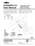
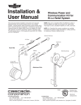
c Installation & User Manual This manual provides installation instructions for Cascade Clamp Open Guard. The kit provides an added level of security to prevent accidental load dropping. Clamp Open Guard requires a definitive action by the driver to help prevent accidental unclamping. The kit is intended for use with all Cascade load bearing Clamps to conform with ANSI/ITSDF B56.1, Section 7.25.7. Clamp Open Guard Switch Activated Models 6806868 and 6806869 NOTE: Kits are UL Classified (File # AU3546) for safety in Electric Battery (UL 583) and IC Engine (UL 558) Indust. Truck type E, ES, G, GS,G/LP/ GS/LPS, LP, LPS, D and DS. NOTE: UL Classified Kits require installation by qualified personnel only without major disturbance, cutting, splicing or soldering of factory installed wiring. Clamp Open Indicator Light Clamp Open Guard Kits Voltage Part No. 12V6806868 24-48V6806869 Switch Clamp Open Circuit Valve AC1974.eps Paper Roll Clamps LayerLP0411.eps Pickers CL4689.eps Carton Clamps CL4690.eps Clamps Part No. 6806872-R4 cascade W corporation Cascade Corp. File No. AU3546 For Technical Support . . . To Order Parts . . . Call: 1-800-227-2233 Fax: 1-888-329-8207 Call: 1-888-227-2233 Fax: 1-888-329-0234 Internet: www.cascorp.com Internet: www.cascorp.com Write: Cascade Corporation, PO Box 20187, Portland, OR 97294 Write: Cascade Corporation, 2501 Sheridan Ave., Springfield, OH 45505 Installation 1 Perform by Qualified Personnel only. Remove cable from positive battery terminal 1 Disconnect the cable from the positive battery terminal. 2 Locate and install the solenoid valve and spacer on the truck cowl using customer supplied .25 in. (6 mm) fasteners. Watch for clearance when the mast is tilt all the way back. The valve is being installed in the clamp OPEN line from the auxiliary valve to the attachment. AC0201.eps IMPORTANT: The valve must be installed in the open circuit ahead of any clamp line check valve pilot lines. 2.10 in. (53 mm) Do not install the coil adjacent to any RF or control devices/ electronics. 3 Connect control valve port 1 to the supply hose going to the attachment. IMPORTANT: When installing the Clamp Open Guard with Cascade’s Adaptive Force Control (AFC), the solenoid valve must be installed between the truck auxiliary valve and the AFC valve. 2 4 Connect solenoid valve port 2 to the supply hose from the truck auxiliary valve clamp OPEN line. IMPORTANT: Verify by visual test, Installation steps 2, 3 and 4. 2 4.80 in. (122 mm) Valve mounting holes: .25 in. or M6 thread Mount Solenoid Valve AC2048.eps 1.62 in. (41 mm) Attachment Revolving Connection Open Clamp Solenoid Valve 2 4 1 AC1013.eps Hoist Control Valve 3 Clamp Auxiliary Valve Truck Relief Valve Truck Hydraulic Pump Truck Tank AC0447.eps 2 Install attachment supply hose to Port 1 Install auxiliary valve hose to Part 2 5 Install cab indicator light on the truck dashboard, overhead 5 guard, or any other easy to see location using customer supplied hardware OR the Velcro strip provided. Clean the mounting surfaces prior to installing the Velcro. Install clamp open indicator light 6 Install the switch to the clamp control lever. Remove the control knob. Position the switch on the handle in a location for comfortable thumb or index finger operation. IMPORTANT: Place the double sided tape under the switch to secure the switch in place. Place the heat shrink tubing over the handle and switch. Using a heat gun, heat the tubing to secure the switch to the handle. Reinstall the knob. Install cable ties as needed for the wires. Avoid pulling, bending or pinching the switch wire. NOTE: UL Classified Kits require installation by qualified personnel only without major disturbance, cutting, splicing or soldering of factory installed wiring. CAUTION: Consult the Lift Truck OEM for proper + power source connection. 7 Connect cable ends to the components as shown. 12V Systems – Connect the fused positive wire from the cable harness to a 12V switched power source, and the ground wire to a chassis ground. 24V–48V Systems – Connect the fused positive wire from the cable harness to a DC-to-DC converter positive output wire and the ground wire to the converter negative output wire. Connect converter inputs to the voltage filter outputs. Connect a 24V–48V switched power source to the voltage filter input wire and connect the filter input ground wire to a chassis ground. AC1975.eps 6 Check the cable routing for pinch points and clearance. Use wire ties as needed. NOTE: When installing on electric trucks, voltage filter 6061953 must be installed. Failure to install voltage filter can cause damage to electrical components. 3 in. (76 mm) for typical hand AC0402.eps WARNING: To reduce risk of fire, replace only with the same type and ratings of fuse. The fused power cable is polarity sensitive. The positive wire must be connected to a positive power source. Cut tubing around button Tape Shrink Tube 8 Reconnect the positive battery terminal to the battery. Cab Light Indicator Solenoid Valve 7 Install switch Handle and Knob Connect Cable Ends Voltage Filter (24V–48V systems only, if equipped) Output System Fuse Input Switched Switch DC to DC Converter (24V–48V systems only, if equipped) Truck Fuse Block Chassis Ground 3 Truck Battery or Power Bus AC2332.eps 8 Positive Battery Terminal Test and Adjustment Perform by Qualified Personnel only. Clamp Open Indicator 1 Test the installation before putting the truck in service. When the truck key is turned ON, the green light should be off. 2 Press the button and observe that the green light turns on. 3 Hoist a load 1 in. off the ground. Operate the clamp open handle several times, the clamp should not open. Lower the load to the ground. Press the button to release the load. Verify that the green light is on while pressing the button. Operation WARNING: All operators must read this section. Before operation, inspect the switch, indicator, valve, wiring and test operation daily. Switch Operators must have a thorough knowledge and understanding of the safe operation of the attachment with which the Clamp Open Guard is used. Solenoid Valve The Clamp Open Guard provides an added level of security to prevent accidental load dropping per current ANSI standards. Clamp Open Guard requires a definitive action by the driver to help prevent accidental unclamping. It acts as a device to prevent accidental activation of the truck’s clamp open circuit. The clamp is allowed to open when the switch is activated and the green light on. AC1977.eps • Press the switch button, then operate the truck clamp open control lever to open the clamp. When the green light is on, the clamp will open normally. Temporarily Disabling System The Clamp Open Guard can be disabled by performing the following steps: • If the clamp will not open when the button is pressed, set the load down, turn off the truck key and troubleshoot the system. Follow Test and Adjustment before returning to service. • Tag equipment as not operational. Do not operate when system is disabled or known to malfunction. NOTE: The system does not work like a drop stop valve that prevents carriage drop or jump when the clamp is opened. The green light does not indicate that the load has been lowered to its optimal position. • Disconnect the two hose ends to the normally-closed solenoid valve and connect them together with a union. • Remove the system power fuse in the cable harness to disable indicator light. WARNING: Residual risk exists to personnel in the work area, operate only in compliance to facility, state and federal standards. The truck and attachment will now operate without the Clamp Open Guard feature. To enable the Clamp Open Guard, reverse the above procedure. System Fuse For this accessory: a) The Weighted Emission Sound Pressure Level (LpA) does not exceed 70 dB(A). Solenoid Valve b) The Value of Whole Body Vibration does not exceed 0,5 m/s^2. c) The Value of Hand-Arm Vibration does not exceed 2,5 m/s^2. Troubleshooting Service only after reading this manual and by Qualified Personnel only. • Check all system fuses. • Verify 12VDC at switch connector. • Check switch function (N/O switch). • Check 12VDC at solenoid when switch is pressed. • Check for 12VDC at Indicator Light when switch is pressed. AC1978.eps 4 Clamp Open Guard 7 6 4 12 $ 5 % 3 @ ! 90 NOTE: To reduce risk of fire, replace with 5A fuse only. # 8 ^ AC2070.eps REF QTY 1 2 3 4 5 6 7 ● ■ u ▲ 1 1 1 1 1 2 1 PART NO. 6806868 6806869 6806867 6004132 6008301 6806863 6822532 6029665 6014987 DESCRIPTION REF QTY 12V Clamp Open Guard ● 24V-48V Clamp Open Guard ■ Clamp Open Indicator Lamp, Green Solenoid Wire Harness Switch Kit Shrink Tube, 1.5 in. (40 mm) ◆ Velcro Adhesive Tape ◆ 8 9 10 11 12 13 14 15 16 Items 1–13. Items 1–11, 14, 15 and 16. Included in Switch Kit 6806863. Included in Solenoid Valve Assembly 6813193. 5 1 1 1 1 1 1 1 1 1 PART NO. 6813193 6813173 6020883 6048803 6806707 6806865 6816503 6816341 6806701 DESCRIPTION Solenoid Valve Assembly Coil, 12V ▲ Solenoid Cartridge ▲ Spacer Fuse, 5 Amp Power Harness, 12V Power Harness, 24-48V Converter Kit Fuse, 2 Amp Do you have questions you need answered right now? Call your nearest Cascade Service Department. Visit us online at www.cascorp.com AMERICAS Cascade Corporation U.S. Headquarters 2201 NE 201st Fairview, OR 97024-9718 Tel: 800-CASCADE (227-2233) Fax: 888-329-8207 Cascade Canada Inc. 5570 Timberlea Blvd. Mississauga, Ontario Canada L4W-4M6 Tel: 905-629-7777 Fax: 905-629-7785 Cascade do Brasil Rua João Guerra, 134 Macuco, Santos - SP Brasil 11015-130 Tel: 55-13-2105-8800 Fax: 55-13-2105-8899 EUROPE-AFRICA Cascade Italia S.R.L. European Headquarters Via Dell’Artigianato 1 37050 Vago di Lavagno (VR) Italy Tel: 39-045-8989111 Fax: 39-045-8989160 Cascade (Africa) Pty. Ltd. PO Box 625, Isando 1600 60A Steel Road Sparton, Kempton Park South Africa Tel: 27-11-975-9240 Fax: 27-11-394-1147 ASIA-PACIFIC Cascade Japan Ltd. 2-23, 2-Chome, Kukuchi Nishimachi Amagasaki, Hyogo Japan, 661-0978 Tel: 81-6-6420-9771 Fax: 81-6-6420-9777 Cascade Korea 121B 9L Namdong Ind. Complex, 691-8 Gojan-Dong Namdong-Ku Inchon, Korea Tel: +82-32-821-2051 Fax: +82-32-821-2055 Cascade-Xiamen No. 668 Yangguang Rd. Xinyang Industrial Zone Haicang, Xiamen City Fujian Province P.R. China 361026 Tel: 86-592-651-2500 Fax: 86-592-651-2571 Cascade Australia Pty. Ltd. 1445 Ipswich Road Rocklea, QLD 4107 Australia Tel: 1-800-227-223 Fax: +61 7 3373-7333 Cascade New Zealand 15 Ra Ora Drive East Tamaki, Auckland New Zealand Tel: +64-9-273-9136 Fax: +64-9-273-9137 Sunstream Industries Pte. Ltd. 18 Tuas South Street 5 Singapore 637796 Tel: +65-6795-7555 Fax: +65-6863-1368 Cascade India Material Handling Private Limited No 34, Global Trade Centre 1/1 Rambaugh Colony Lal Bahadur Shastri Road, Navi Peth, Pune 411 030 (Maharashtra) India Phone: +91 020 2432 5490 Fax: +91 020 2433 0881 c © Cascade Corporation 2012 09-2012 Part Number 6806872-R4