1
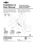
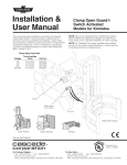
c Installation & User Manual Wireless Power and Communication Kit for Hi-Lo Relief System This manual provides installation instructions for Cascade Wireless Power and Communications Kit for Hi-Lo Relief System. This kits allows 12W of inductive power transfer when the ST and SR units are in alignment. At all times a 2.4 Ghz RF signal provides two digital switch input and outputs (5A total) each direction as well as providing a generic CAN bus node. The RF features have a 10 M range and meet EMC (EN 12895) and FCC standards. NOTE: Kits are UL Classified (File # AU3546) for safety in Electric Battery (UL 583) and IC Engine (UL 558) Indust. Truck type E, ES, G, GS,G/LP/ GS/LPS, LP, LPS, D and DS. NOTE: UL Classified Kits require installation by qualified personnel only without major disturbance, cutting, splicing or soldering of factory installed wiring. Solenoid Harness 5A Fuse Switch Kit 12V Power Truck Side CAN Battery Input/ Output ST and SR Wireless Devices Mounting Group CAN Input/ Output Attachment Side AC2423.eps cascade corporation For Technical Support . . . Call: 1-800-227-2233 Fax: 1-888-329-8207 Internet: www.cascorp.com Write: Cascade Corporation, PO Box 20187, Portland, OR 97294 Uses Cascade Corp. File No. AU3546 Electrical Components To Order Parts . . . Call: 1-888-227-2233 Fax: 1-888-329-0234 Internet: www.cascorp.com Write: Cascade Corporation, 2501 Sheridan Ave., Springfield, OH 45505 Kit Installation Perform by Qualified Personnel only. 1 Mount the ST and SR units so that the faces are parallel and .25-1.00 in. (6-25 mm) apart. Orient the cables as required. If mounting hardware is included, modifications may be required for your installation. Mount the SR slider mechanism fixed to the carriage. Use the load backrest holes if possible. Make sure the top of the slider is not above the carriage or attachment and the bottom is hidden behind the frame or high enough to avoid hitting the ground. Mount the ST unit bracket to the mast so that when the carriage is in its lowest position, the SR unit is supported near the top of the slider rail. Check for clearance through the full range of slide movement while tilting forward and fully back. 1 Mount ST unit and bracket to mast. Attachment Connections ST Unit .25-1.00 in. (6-25 mm) SR Unit Truck Connections 2 1 Route the SR unit cable so movement of the SR along the guide does not bind or snag. Anchor the cable as required. 3 Disconnect the negative battery terminal as directed by the truck OEM. NOTE: UL Classified kits require installation by qualified personnel only, without major disturbance of cutting, splicing or soldering of factory installed wiring. Mount SR slider mechanism to carriage AC2417.eps AC2418.eps 2 Anchor cable 3 CAUTION: Consult the Lift Truck OEM for proper + power source connection. GA0436.eps 2 Remove cable from negative battery terminal. 4 Connect cable ends to the components as shown. 12V Systems – Connect the fused positive wire from the cable harness to a 12V switched power source, and the negative wire to a ground. Check the cable routing for pinch points and clearance. Use wire ties as needed. WARNING: To reduce risk of fire, replace only with the same type and ratings of fuse. The fused power cable is polarity sensitive. The positive wire must be connected to a positive power source. SR Circuit on Carriage & Attachment ST Circuit on Mast & Truck CAN Circuit (Not Used) CAN Circuit (Not Used) Switch Kit 6832381 Harness 6843136 Harness 6843135 Attachment Input/Output Circuit Harness 6008301 Solenoid Valve Truck Input/Output Circuit Switched Cascade Battery 6075736 Fuse, 5A Truck Fuse Block Truck Battery AC2424.eps Test Procedure Perform by Qualified Personnel only. At the SR unit, connect only Cascade Battery 6075736 to the connector marked 'BATTERY'. With power ON at the ST unit: • Align units and verify inductive power yeilds 14V minimum at SR 6 pin LOAD line connector. Pin 1(+) and Pin 6(-). • Move units out of alignment and verify LOAD line voltage drops to the battery voltage. • Turn off power to ST unit, wait 5 minutes (do not vibrate or bump the SR unit) and verify that the LOAD line voltage drops to near 0V. 3 Wireless Power and Communication Kit 3 4 8 2 7 2 6 5 1 AC2421.eps 9 REF 1 2 3 4 QTY PART NO. 1 1 1 1 6842546 6829906 6842851 6806708 6048139 DESCRIPTION REF Wireless Power/Comm Kit – 12V Wireless Power/Comm Device Seal Plug Fuse, 5 Amp Cable Harness QTY PART NO. 5 6 7 1 1 1 6843167 6843136 6843135 6008301 Harness Kit Harness-ST I/O Harness-SR I/O Harness-Solenoid DESCRIPTION 8 9 1 1 6832381 6843082 Switch Kit ● Mounting Kit ● ● See following parts page for breakdown. 4 Switch Kit 6 REF QTY 1 1 2 3 4 5 6 4 5 2 3 1 1 1 2 2 2 PART NO. 6832381 6091430 6092966 6832382 6076098 686454 6014987 DESCRIPTION Switch Kit Angle Bracket Proximity Switch Cable Assembly Capscrew, M4 x 6 Washer, M4 Adhesive Tape AC2422.eps Mounting Group REF QTY 1 2 3 4 5 6 7 8 9 10 11 12 13 14 15 16 17 18 19 20 5 @ ! ( % 9 ^ 3 4 1 8 2 # 0 ) # * @ $ 6 ! 7 AC2409.eps & 5 4 1 1 1 1 1 1 1 2 1 3 3 4 6 8 8 1 6 2 2 PART NO. 6843082 6405844 6829954 6830008 6839466 6839469 6839966 6840040 6840048 6840630 6840657 685901 768202 787372 206315 220436 678993 685862 767414 768220 787373 DESCRIPTION Mounting Group Capscrew, M4 x 12 Mounting Plate Mounting Plate Carriage Rail Bracket Stop Bracket Bracket Bracket Lockwasher, M5 Nut, M5 Capscrew, M8 x 20 Lockwasher, M8 Capscrew, M6 x 16 Lockwasher, M6 Capscrew, M5 x 40 Nut, M8 Capscrew, M5 x 20 Capscrew, M8 x 25 Battery Assembly 2 1 4 FP2126.eps 3 REF QTY 1 2 3 4 1 1 4 4 PART NO. 6843202 6075736 6094986 6071505 685899 DESCRIPTION Battery Assembly Battery Retainer Clip Avssembly Capscrew Lockwasher 6 Specifications Description and Operation: A three function device providing 1) Inductive battery charger for Cascade Li-Ion battery's, 2) RF CAN bus node with 10m range and 3) RF digital switching device with two remote inputs and two remote outputs with 60W (limited by OCP) of switching power provided by the Cascade Battery as well as a 16W* load line for remote sensor/controller power. Performance RF Two main components include: ST = Transmitter, typically located on the host device and the SR = Receiver, typically located remotely and requires a Cascade Battery for 'out of range' power. * Actual power available depends on battery condition. Electrical ST Input Voltage 9V to 16V DC (12V DC Nominal) ST Start Up current requirement 5A ST Typical operating current <3A Note: Input is fused at 5A per UL requirements. ST Max power required (at 14.4v) 72W Inductive Power Transfer (in Range **) 12W - nom. 12VDC/1A SR Input Voltage: Cascade Battery Voltage only (12.5V) RF Range 10m (in typical truck application, Not LOS) Data rate 1Mbps Operating Freq 2.4-2.4835GHz RF CANbus node (bidirectional) Protocol independent, J1939,CANopen and DeviceNet supported CAN message Response Time 66ms (avg), 106ms (max) CAN PNG Address Limits (factory set) FFC0 to FFC1 inclusive FF00 to FF34 inclusive Note: - PNG address will be allowed in either direction: - FF01 message is sent every 1 second. Performance SR Power required (RF Data Only) 75mA nom (.85W) 2x2 GPIO 2 x Input and 2 x Output at each transceiver Inputs PNP Sensors suitable Input voltage 9 to 24 VDC Outputs Local (+) voltage, 3A per channel or 5A total ST = input voltage SR = (see Load Line & GPO voltage above) SR load Line & GPO voltage 14.4V +/- 5% (in Range**) SR load Line & GPO voltage Cascade Battery Voltage (out of Range**) (12.5V to 10.0V min) SR Load Line Over Current Protection (OCP) 1.6A (shutdown with auto reset) GPO Over Current Protection (OCP) 5A typical total, +2.5A / -1.2A (shutdown with auto reset) Recommended Limits: -3A on any one channel alone (tested to 17% duty cycle) -1.5A / channel simultaneous (recommended) (tested to 80% duty cycle) GPIO Response 45ms (avg), Time GPO Latching 8kV any contact and 15kV air to case Reverse Input Voltage at ST only 14.4 Volts (ST) Unprotected (SR) High Voltage protected (ST) None GPO's un-latch after 1.5s (Voltage goes 'Low' after 1.5s when power goes off). ***Battery Information Protection ESD 80ms (max) SAE J1455 Double Jump 28.7V Surge Limit 41V Use appropriate dc/dc converter and filters Use only Cascade Li-Ion Battery pn 6075736 3 cell 11.1V 2200 mAH Battery Rating 12.54V - 9.8V, 2200 mAH, 6.5A current load limited Shuts down when voltage is less than 9.8V Battery Life (out or Range*) 27 hrs RF full time, No GPO load, SR 'ON' 120 hrs uninterrupted sleep mode, SR 'OFF' Inductive Power at optimal range* Short Circuit protection at GPO's (ST and SR) Protected: Auto Reset 7 Cascade Li-Ion Batt charging circuit Fully charge in 2.5 hrs at optimal alignment. Seamless Transition between Battery/Inductive Power Battery Voltage / 14.4V SR Power Management Inductive Power at optimal Alignment (range*) 12W Unused Power is charging the Battery. Demand over 12W, draws additional power from Battery Up to 72W nom. /2200mAhrs at full charge. Not Aligned for Inductive Power Up to 72W nom. /2200mAhrs at full charge on Load Line and GPO from Battery only. SR Power required (RF Data Only) 75mA Nom. (.85W) Environmental Vibration 10-12g RMS Drop Test 3 ft bench drop (in packaging) Operating Temp -40 to 60C (140F) Storage Temp -55 to 85C (185F) Sealing to environment IP 66 Humidity to 90% (no condensation) Physical Dimensions and Mounting Diameter 145mm Thickness 37mm Weight (pair) 2.0kg Mounting holes M6 x 4 x 12 deep, equally spaced Mounting Hole Bolt Circle 137mm dia (equally spaced) *Range: Distance and alignment for optimal inductive power transfer Power Trans Distance 6mm to 25mm (Over 25mm, power transfer eff. deteriorates) Mis Alignment allowance (center line axis) 12mm (Over 12mm, power transfer eff. deteriorates) Angular Alignment allowance (non parallel face angle) +/- 15 deg. Misalignment causes power transfer eff. to deteriorate. Radial Orientation Limits for mounting (around center line) None Sleep Mode time out at SR after ST powered 'off' 5 minutes Sleep mode power demand 18mA Nom. Sleep Mode 'wake up' Aligned: Power up ST. Not Aligned: Vibration is required. ST power 'ON' to communicate. 'Wake Up' Accelerometer Sensitivity Field Adjustable, contact Cascade Corp Wake Up response time 2 sec (max) Wire Color and Function Code Wire No. Color STx SRx 1 Red Fork Lift Battery Positive Cascade Battery Positive 2 Black Fork Lift Battery Negative Cascade Battery Negative Cable Gland 22mm tall (approx.) 3 Yellow CAN Hi CAN Hi Cable Length 1.5M=SR, I.0M=ST 4 Green CAN Lo CAN Lo 5 Grey No Connection Load Positive 6 White No Connection Load GND 7 Orange GPI No.1 GPI No.1 8 Violet GPI No.2 GPI No.2 9 Blue GPO No.1 GPO No.1 10 Brown GPO No.2 GPO No.2 Microchip Wi-Fi Module Information Microchip MRF24W80MA Wi-Fi Module Data 2.4 GHz 802.11 Low Power Transceiver Wi-Fi Certified for 802.11b RoHS compliant CE Compliant FCC Certified (US FCC ID: W7O-ZG2100-ZG2101) IC Certified (IC:8248A-G21ZEROG) Fully Compliant with EU and meets R&ETT Directive for Radio Spectrum Radio Type Approval Certified in Europe (ETST) and Japan ARIB). CE Mark YES - DoC maintained by OEM (PbP). EN12895, FCC Part 18, RoHS UL Classified File # AU3546 (UL 558/583) WFA ID: WFA7150 c © Cascade Corporation 2014 8 12-2014 Part Number 6843219-R1