1
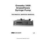
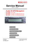
INTERBUS-S Device
Certification
September 1996
1. Certification Background
3. Governing Body
Certification is the guarantee that your device is
INTERBUS-S compatible. This process starts in the
design stage of a product and continues until the
device is finally submitted to the conformance testing
body. This data sheet will explain the certification
structure, requirements, benefits of certification and
design considerations with certification in mind.
The INTERBUS-S Club is the governing body of the
certification process. They have the responsibility of
controlling all the test methods, procedures, related
specifications and documentation. Along with these
duties, the club issues certification certificates and
selects / audits test facilities. Figure 1 shows the
relationship and responsibilities of the certification
organization.
2. Benefits of Certification
4. Certification Requirements
Confidence that your device has been reviewed and
deemed compatible with all other INTERBUS-S
devices is one of the biggest benefits of certification.
Other advantages are as follows:
The first step in certifying a device is the scheduling
of a test date. The device must be sent on this date
along with the following items:
•
•
•
•
Schematic evaluation
Possible design improvement suggestions
Use of the INTERBUS-S Club's compatible logo
Product will be published in the INTERBUS-S
Club's Info-Service
• World wide exposure
• Acceptance for projects that mandate
INTERBUS-S certified products
• Schematic drawings of the INTERBUS-S
interface
• PCB layout and assembly drawings
• Parts list for the INTERBUS-S interface
• Device user manual / setup instructions
• Data sheets for components not listed in this
document
• If the Peripheral Communications Protocol
(PCP) is used, send the following files:
A.) KBL.DAT, VFD.DAT and OV.DAT or the
PICS file
Certification Body
INTERBUS-S Club
Blomberg, Germany
011-49-5235-342100
After the testing is complete, a report will be sent from
the test facility to the submitting party. If this report
shows a positive result, the applicant must then send
the report to the INTERBUS-S Club. The club is then
responsible for issuing the official certificate allowing
the applicant to use the "INTERBUS-S Compatible"
certification logos on their device (shown in figure 2).
This certificate is valid for 3 years. At the end of this
period the applicant must resubmit the test report for
renewal.
Certificate
Test Method
Test Report
Lab Recognition
Auditing of Lab
Product
Applicant
Agreement
Test Report
Test Laboratory
Fraunhofer Institute
D-76131 Karlsruhe
Germany
011-49-0721-6091-0
0666A012
Figure 1. INTERBUS-S Certification Structure
1
each component that needs tested and there are no
guaranties that your selected component will pass.
To be on the safe side, develop with approved
components listed in this document. See Tables 1
through 10. Surface mount components are marked
with an asterisk.
PCP-Protocol 2.0
INTERBUS-S
INTERBUS-S
COMPATIBLE
COMPATIBLE
Certification Symbol for
Process Data Devices
Certification Symbol for
PCP Protocol Devices
Table 1. Remote Bus Drivers and Receivers
Part Number
Functional Description
Manufacturer
AD485
AD485*
DS26C31TN
DS26C31TM*
DS26C32ATN
DS26C32AIM*
DS96173N
SN75172N
SN75173N
SN75176BP
SN75176BD*
SN75179BP
SN75179BD*
Differential RS 485 Transceiver
Differential RS 485 Transceiver
Quad differential line driver
Quad differential line driver
Quad differential line receiver
Quad differential line receiver
Quad differential line receiver
Quad differential line driver
Quad differential line receiver
Differential bus transceiver
Differential bus transceiver
Differential driver and receiver
Differential driver and receiver
Analog Devices
Analog Devices
National Semiconductor
National Semiconductor
National Semiconductor
National Semiconductor
National Semiconductor
Texas Instruments
Texas Instruments
Texas Instruments
Texas Instruments
Texas Instruments
Texas Instruments
0666A011
Figure 2. INTERBUS-S Certification Logos
5. Design Considerations
Certification of INTERBUS-S devices can be virtually
assured by using proper design techniques for printed
circuit boards, isolating of the protocol chip (SuPI) and
the INTERBUS-S network signals and by using
components listed on the approved components
listing.
* = Surface mount component
0666A001
a. Circuit Board Layout
Table 2. Fiber Optic Transmitters and Receivers
Circuit board layout should be considered when
designing an INTERBUS-S bus interface. The use of
proper power and grounding techniques for PCB and
SMT type boards will greatly increase your chances
to pass the external noise immunity test for certification. This external noise immunity test is carried out
in accordance with IEC 801-4 and must meet the
criteria of test class 3, minimum. Information on
layout techniques is available through the
INTERBUS-S Club.
Part Number
Functional Description
Manufacturer
TORX 104
QFBR-1607
HFX 6015-548
HFX 6015-536
Fiber optic receiver
Fiber optic transmitter
Fiber optic transmitter
Fiber optic transmitter
Toshiba
Hewlett Packard
Honeywell
Honeywell
0666A002
Table 3. Logic ICs
b. Bus Isolation
Isolation is optional for certification but will improve
the odds of passing the test. By isolating the incoming bus from the protocol chip (SuPI), bus fidelity will
be greatly enhanced. Information for the design can
be found in the SuPI manual (IBS SUPI II HB-E,
2758787, available from Phoenix Contact).
c. Component Selection
Part Number
Functional Description
Manufacturer
CD74ACT00E
HD74ACT00P
MC74ACT00N
MM74ACT00PC
TC74ACT00P
CD74ACT74E
HD74ACT74P
MC74ACT74N
MM74ACT74PC
TC74ACT74P
MC74HC14D
PC74HC14T*
SN74HC14N*
Quad 2 input nand gate
Quad 2 input nand gate
Quad 2 input nand gate
Quad 2 input nand gate
Quad 2 input nand gate
Dual D type flip flop
Dual D type flip flop
Dual D type flip flop
Dual D type flip flop
Dual D type flip flop
Hex schmitt-trigger invertor
Hex schmitt-trigger invertor
Hex schmitt-trigger invertor
Harris Semiconductor
Hitachi
Motorola
National Semiconductor
Toshiba
Harris Semiconductor
Hitachi
Motorola
National Semiconductor
Toshiba
Motorola
Phillips
Texas Instruments
* = Surface mount component
Product certification CANNOT be
achieved with the use of nonstandard
parts in the INTERBUS-S interface.
0666A006
Table 4. Power Supply Monitors/Supervisors
Part Number
If the developer chooses to select unapproved parts
there will be extra steps required to have these
components added to the list in order to obtain
certification. Non-standard parts need to be tested to
ensure their functionality. This process is carried out
by the INTERBUS-S Club in Germany. The first step
for component testing is to arrange a test appointment and pay the testing fee. This fee will be paid for
MAX700L
MAX709L
Functional Description
Adjustable power supply
monitor with reset
Power supply monitor with
4.65V reset threshold
Manufacturer
Maxim
Maxim
0666A004
2
Table 5. Opto Couplers
Table 8. Expansion Input Registers
Part Number
Functional Description
Manufacturer
Part Number
Functional Description
Manufacturer
HCPL0601
HCPL0611
HCPL2601
HCPL2611
HCPL2630
HCPL2631
HCPL4661
Q62703-N77
HCPL2601
TLP2601
Opto coupler
Opto coupler
Opto coupler
Opto coupler
Opto coupler
Opto coupler
Opto coupler
Opto coupler
Opto coupler
Opto coupler
Hewlett Packard
Hewlett Packard
Hewlett Packard
Hewlett Packard
Hewlett Packard
Hewlett Packard
Hewlett Packard
Siemens
Texas Instruments
Toshiba
CD74HC165E
CD74HC165M*
MM74HC165M*
PC74HC165T*
M74HC165M1*
SN74HC165D*
CD74HCT165E
PC74HCT165P
M74HC597B1N
TC74HC597AP
CD74HCT597E
PC74HCT597P
Parallel-load serial shift register
Parallel-load serial shift register
Parallel-load serial shift register
Parallel-load serial shift register
Parallel-load serial shift register
Parallel-load serial shift register
Parallel-load serial shift register
Parallel-load serial shift register
Shift register w/input latches
Shift register w/input latches
Shift register w/input latches
Shift register w/input latches
Harris Semiconductor
Harris Semiconductor
National Semiconductor
Phillips
SGS-Thomson
Texas Instruments
Harris Semiconductor
Phillips
SGS-Thomson
Toshiba
Harris Semiconductor
Phillips
0666A005
Part Number
Functional Description
Manufacturer
TL7705ACD*
TL7705ACP
TL7705ACD*
Supply voltage supervisor
Supply voltage supervisor
Supply voltage supervisor
SGS-Thomson
Texas Instruments
Texas Instruments
Table 9. Local Bus Buffers, Drivers and Selectors
0666A003
* = Surface mount component
Table 7. Expansion Output Registers
Part Number
Functional Description
Manufacturer
CD74HC164E
MC74HC164D*
PC74HC164T*
SN74HC164N
CD74HCT164E
MM74HCT164N
PC74HCT164P
MM74HC594P
MM74HC594D*
SN74HC594P
SN74HC594D*
MC74HC595N
MC74HC595AN
SN74HC595N
SN74HC595D*
SN74HC595TP*
MM74HCT595P
MM74HCT595D*
SN74HCT595P
SN74HCT595D*
Parallel out serial shift register
Parallel out serial shift register
Parallel out serial shift register
Parallel out serial shift register
Parallel out serial shift register
Parallel out serial shift register
Parallel out serial shift register
Shift register w/output latches
Shift register w/output latches
Shift register w/output latches
Shift register w/output latches
Shift register w/output latches
Shift register w/output latches
Shift register w/output latches
Shift register w/output latches
Shift register w/output latches
Shift register w/output latches
Shift register w/output latches
Shift register w/output latches
Shift register w/output latches
Harris Semiconductor
Motorola
Phillips
Texas Instruments
Harris Semiconductor
National Semiconductor
Phillips
National Semiconductor
National Semiconductor
Texas Instruments
Texas Instruments
Motorola
Motorola
Texas Instruments
Texas Instruments
Texas Instruments
National Semiconductor
National Semiconductor
Texas Instruments
Texas Instruments
Part Number
Functional Description
Manufacturer
74ACT240PC
CD74ACT240E
CD74ACT258E
HD74ACT258P
MC74ACT258N
MM74ACT258PC
TC74ACT258P
Buffers and line drivers
Buffers and line drivers
2 to 1 line data selectors
2 to 1 line data selectors
2 to 1 line data selectors
2 to 1 line data selectors
2 to 1 line data selectors
Fairchild
Harris Semiconductor
Harris Semiconductor
Hitachi
Motorola
National Semiconductor
Toshiba
0666A009
Table 10. Discrete Component Values
0666A007
* = Surface mount component
0666A008
* = Surface mount component
Table 6. Voltage Regulator
Table 11. Phoenix Contact Supplied Component
Part Number
Type
Manufacturer
MCO1400B-16MHz
VX-4231-16MHz
16MHz +/- 100pp
mCL=16PF ESR=50Ω
220µF 6.3V 20%
LLAG3VB-220(M)TPA(F2.5)
3.3µF 16V 20%
15nF 650V 20%
100nF 16V 20%
22-68pF 16V 20%
100W 0.25W 1%
15W 0.25W 1%
220W 0.25W 1%
390W 0.25W 1%
2.7KW 0.125W 10%
4.7KW 0.125W 10%
1MW 0.125W 10%
Quartz Oscillator
Quartz Oscillator
Crystal
TQE
JVC
Capacitor
Nippon Chemicon
Capacitor
Capacitor
Capacitor
Capacitor
Resistor
Resistor
Resistor
Resistor
Resistor
Resistor
Resistor
0666A010
Part
Functional Description
Order Number
IBS SµPI PLCC
IBS SµPI II PLCC
IBS SµPI II QFP*
IBS SRE1 QFP*
Slave protocol IC
Slave protocol IC
Slave protocol IC
Micro controlled
expansion registers
27 59 14 2
27 58 40 2
27 58 41 5
* = Surface mount component
27 52 85 1
0666A013
3