1
SC-206X Series
User Manual
Optically Isolated and Electromechanical Relay Boards
December 1996 Edition
Part Number 371167A-01
© Copyright 1989, 1996 National Instruments Corporation.
All Rights Reserved.
Limited Warranty
The SC-206X Series boards are warranted against defects in materials and workmanship for a period of one year
from the date of shipment, as evidenced by receipts or other documentation. National Instruments will, at its option,
repair or replace equipment that proves to be defective during the warranty period. This warranty includes parts and
labor.
A Return Material Authorization (RMA) number must be obtained from the factory and clearly marked on the
outside of the package before any equipment will be accepted for warranty work. National Instruments will pay the
shipping costs of returning to the owner parts which are covered by warranty.
National Instruments believes that the information in this manual is accurate. The document has been carefully
reviewed for technical accuracy. In the event that technical or typographical errors exist, National Instruments
reserves the right to make changes to subsequent editions of this document without prior notice to holders of this
edition. The reader should consult National Instruments if errors are suspected. In no event shall National
Instruments be liable for any damages arising out of or related to this document or the information contained in it.
EXCEPT AS SPECIFIED HEREIN, NATIONAL INSTRUMENTS MAKES NO WARRANTIES, EXPRESS OR IMPLIED,
AND SPECIFICALLY DISCLAIMS ANY WARRANTY OF MERCHANTABILITY OR FITNESS FOR A PARTICULAR
PURPOSE. CUSTOMER'S RIGHT TO RECOVER DAMAGES CAUSED BY FAULT OR NEGLIGENCE ON THE PART
OF NATIONAL INSTRUMENTS SHALL BE LIMITED TO THE AMOUNT THERETOFORE PAID BY THE CUSTOMER.
NATIONAL INSTRUMENTS WILL NOT BE LIABLE FOR DAMAGES RESULTING FROM LOSS OF DATA, PROFITS,
USE OF PRODUCTS, OR INCIDENTAL OR CONSEQUENTIAL DAMAGES , EVEN IF ADVISED OF THE POSSIBILITY
THEREOF. This limitation of the liability of National Instruments will apply regardless of the form of action,
whether in contract or tort, including negligence. Any action against National Instruments must be brought within
one year after the cause of action accrues. National Instruments shall not be liable for any delay in performance due
to causes beyond its reasonable control. The warranty provided herein does not cover damages, defects,
malfunctions, or service failures caused by owner's failure to follow the National Instruments installation, operation,
or maintenance instructions; owner's modification of the product; owner's abuse, misuse, or negligent acts; and
power failure or surges, fire, flood, accident, actions of third parties, or other events outside reasonable control.
Copyright
Under the copyright laws, this publication may not be reproduced or transmitted in any form, electronic or
mechanical, including photocopying, recording, storing in an information retrieval system, or translating, in whole
or in part, without the prior written consent of National Instruments Corporation.
Trademarks
LabVIEW ®, NI-DAQ ®, and RTSI ® are trademarks of National Instruments Corporation.
Product and company names listed are trademarks or trade names of their respective companies.
WARNING REGARDING MEDICAL AND CLINICAL USE
OF NATIONAL INSTRUMENTS PRODUCTS
National Instruments products are not designed with components and testing intended to ensure a
level of reliability suitable for use in treatment and diagnosis of humans. Applications of
National Instruments products involving medical or clinical treatment can create a potential for
accidental injury caused by product failure, or by errors on the part of the user or application
designer. Any use or application of National Instruments products for or involving medical or
clinical treatment must be performed by properly trained and qualified medical personnel, and all
traditional medical safeguards, equipment, and procedures that are appropriate in the particular
situation to prevent serious injury or death should always continue to be used when National
Instruments products are being used. National Instruments products are NOT intended to be a
substitute for any form of established process, procedure, or equipment used to monitor or
safeguard human health and safety in medical or clinical treatment.
Operator's Safety Summary
The general safety information in this summary is for both operating and servicing personnel.
Specific warnings are found throughout the manual where they apply but may not appear in this
summary.
Terms
In this manual, Warning statements identify conditions or practices that could result in personal
injury, loss of life, or damage to equipment or other property.
1. Heed all warnings and safety instructions.
2. Never make any signal or cable connection or disconnection when devices are powered on.
All connections must be made with devices powered off. Failure to do so can result in a
shock hazard.
3. If any voltage potentials can possibly exceed 30 V–particularly potentials across the
optocouplers or relays–the SC-206X Series board must be completely enclosed in order to
protect the operator from shock when devices are powered on. Do not leave the SC-206X
Series boards uncovered under these circumstances.
Contents
About This Manual ..............................................................................................................ix
Organization of This Manual ...........................................................................................ix
Conventions Used in This Manual...................................................................................x
Related Documentation....................................................................................................x
Customer Communication ...............................................................................................xi
Chapter 1
Introduction .......................................................................................................................... 1-1
What Your Kit Should Contain...................................................................................... 1-3
Software ......................................................................................................................... 1-3
Optional Equipment ....................................................................................................... 1-4
Unpacking ...................................................................................................................... 1-4
Chapter 2
SC-2060 Board ..................................................................................................................... 2-1
Specifications................................................................................................................. 2-3
Optically Isolated Digital Input.......................................................................... 2-3
Power Requirement (from Host Board or External Power Supply)................... 2-3
Physical .............................................................................................................. 2-4
Operating Environment...................................................................................... 2-4
Storage Environment.......................................................................................... 2-4
Mounting and Connection to Data Acquisition Boards................................................. 2-4
Chapter 3
SC-2061 Board ..................................................................................................................... 3-1
Specifications................................................................................................................. 3-3
Optically Isolated Digital Output....................................................................... 3-3
Power Requirement (from Host Board or External Power Supply)................... 3-3
Physical .............................................................................................................. 3-4
Operating Environment...................................................................................... 3-4
Storage Environment.......................................................................................... 3-4
Mounting and Connection to Data Acquisition Boards................................................. 3-4
Chapter 4
SC-2062 Board ..................................................................................................................... 4-1
Specifications................................................................................................................. 4-3
Electromechanical Relay Digital Output ........................................................... 4-3
Power Requirement (from Host Board or External Power Supply)................... 4-4
Physical .............................................................................................................. 4-4
Operating Environment...................................................................................... 4-4
Storage Environment.......................................................................................... 4-4
Mounting and Connection to Data Acquisition Boards................................................. 4-4
© National Instruments Corporation
v
SC-206X Series User Manual
Contents
Chapter 5
Installation and Operation .............................................................................................. 5-1
Hardware Installation..................................................................................................... 5-1
Internal or External Power Selection ................................................................. 5-4
SC-206X Series Board Connection.................................................................... 5-5
Operation........................................................................................................................ 5-8
Safety Information ......................................................................................................... 5-9
Appendix A
HCPL-2611-060 Technical Data ...................................................................................A-1
Appendix B
Motorola Array Technical Data ...................................................................................B-1
Appendix C
American Zettler Relay Technical Data ....................................................................C-1
Appendix D
Customer Communication..............................................................................................D-1
Glossary ......................................................................................................................Glossary-1
Index .................................................................................................................................Index-1
SC-206X Series User Manual
vi
© National Instruments Corporation
Contents
Figures
Figure 1-1.
Figure 1-2.
SC-2060 Board Connected to Host Data Acquisition Board
Via an SC-2050 Board ....................................................................................... 1-2
SC-2060 Boards and SC-2050 Board Mounted in 19 in. Rack Mount
with Connection to Host Data Acquisition Board ............................................. 1-2
Figure 2-1.
Figure 2-2.
Figure 2-3.
SC-2060 Board Parts Locator Diagram ............................................................. 2-1
SC-2060 Power Circuit ...................................................................................... 2-2
Onboard Equivalent Circuit ............................................................................... 2-2
Figure 3-1.
Figure 3-2.
SC-2061 Board Parts Locator Diagram ............................................................. 3-1
SC-2061 Onboard Equivalent Power Circuit..................................................... 3-2
Figure 4-1.
Figure 4-2.
SC-2062 Board Parts Locator Diagram ............................................................. 4-1
SC-2062 5 V Onboard Equivalent Circuit ......................................................... 4-2
Figure 5-1.
Figure 5-2.
Figure 5-3.
Figure 5-4.
Figure 5-5.
Figure 5-6.
Mounting Locations for SC-205X and SC-206X Series Boards ....................... 5-2
Attaching a Mountable Board to the Chassis..................................................... 5-2
Double-Height Mounting................................................................................... 5-3
Location of the External Power Screw Terminals ............................................. 5-5
Power Selection Settings for Switch S1............................................................. 5-5
Connecting SC-206X Series Boards to Data Acquisition Boards
via the SC-205X Series Cable Adapter Boards ................................................. 5-6
Pinout for I/O Connector J1............................................................................... 5-7
Figure 5-7.
Tables
Table 1-1.
Data Acquisition Boards for Use with SC-206X Series Boards........................ 1-1
Table 2-1.
Data Acquisition Boards for Use with the SC-2060 Board ............................... 2-4
Table 3-1.
Data Acquisition Boards for Use with the SC-2061 Board ............................... 3-4
Table 4-1.
Data Acquisition Boards for Use with the SC-2062 Board ............................... 4-5
Table 5-1.
Table 5-2.
Amount of Power Data Acquisition Boards Supply .......................................... 5-4
SC-205X Series Connectors Compatible with SC-206X Series........................ 5-8
© National Instruments Corporation
vii
SC-206X Series User Manual
About This Manual
This manual describes the mechanical and electrical aspects of the SC-206X Series boards and
contains information about installing and operating the boards. The SC-206X Series consists of
three digital signal conditioning boards you can use with National Instruments data acquisition
boards–the SC-2060 optically isolated digital input board, the SC-2061 optically isolated digital
output board, and the SC-2062 electromechanical relay digital output board. You can use the
SC-206X Series boards for digital signal conditioning on the Macintosh NuBus computers with
the NB Series and Lab-NB boards, the IBM Personal System/2 (PS/2) Micro Channel computers
with the MC Series boards, and IBM PC/XT/AT and compatible computers with the AT Series
and Lab-PC+ boards. Each of the SC-206X Series boards is described in detail in this manual.
Organization of This Manual
The SC-206X Series User Manual is organized as follows:
•
Chapter 1, Introduction, describes the SC-206X Series boards; lists the contents of your
SC-206X Series kit; describes the optional equipment and software support; and explains
how to unpack your SC-206X Series board.
•
Chapter 2, SC-2060 Board, describes the SC-2060 board in detail including function,
compatibility, specifications, mounting, and connection.
•
Chapter 3, SC-2061 Board, describes the SC-2061 board in detail including function,
compatibility, specifications, mounting, and connection.
•
Chapter 4, SC-2062 Board, describes the SC-2062 board in detail including function,
compatibility, specifications, mounting, and connection.
•
Chapter 5, Installation and Operation, describes the installation and operation of the
SC-206X Series boards. Hardware installation, signal connections to the boards, and
operation are discussed.
•
Appendix A, HCPL-2611-060 Technical Data, contains technical data on the
Hewlett-Packard Company high-speed TTL compatible optocoupler.
•
Appendix B, Motorola Array Technical Data, contains technical data on the Motorola
Corporation ULN2801 array.
•
Appendix C, American Zettler Relay Technical Data, contains technical data on American
Zettler Corporation relays.
•
Appendix D, Customer Communication, contains forms you can use to request help from
National Instruments or to comment on our products and manuals.
•
The Glossary contains an alphabetical list and description of terms used in this manual,
including abbreviations, acronyms, metric prefixes, mnemonics, and symbols.
•
The Index contains an alphabetical list and description of terms in this manual, including the
page where you can find each one.
© National Instruments Corporation
ix
SC-206X Series User Manual
About This Manual
Conventions Used in This Manual
The following conventions are used in this manual:
italic
Italic text denotes emphasis or a cross reference.
MIO-16
MIO-16 refers to the AT-MIO-16, AT-MIO-16D, AT-MIO-16F-5,
AT-MIO-16X, AT-MIO-64F-5, MC-MIO-16, NB-MIO-16, and
NB-MIO-16X boards.
DIO-24
DIO-24 refers to the PC-DIO-24, MC-DIO-24, and NB-DIO-24 boards.
DIO-32F
DIO-32F refers to the AT-DIO-32F, MC-DIO-32F, and NB-DIO-32F
boards.
DIO-96
DIO-96 refers to the PC-DIO-96 and NB-DIO-96 boards.
Lab boards
Lab boards refers to the Lab-PC+ and Lab-NB boards.
PS/2
PS/2 refers to IBM Personal System/2 computers.
PC/XT/AT
PC/XT/AT refers to IBM PC/XT, PC AT, and compatible computers.
Abbreviations, acronyms, metric prefixes, mnemonics, symbols, and terms are listed in the
Glossary.
Related Documentation
The following National Instruments document contains information that may be helpful as you
read this manual:
•
SC-205X Series User Manual (part number 320385-01)
The following National Instruments documents may also be helpful to you depending on the type
of system you are using with your SC-206X Series boards.
•
Macintosh NuBus users
-
Lab-NB User Manual (part number 320174-01)
-
NB-DIO-24 User Manual (part number 320094-01)
-
NB-DIO-32F User Manual (part number 320095-01)
-
NB-MIO-16 User Manual (part number 320295-01)
-
NB-MIO-16X User Manual (part number 320157-01)
SC-206X Series User Manual
x
© National Instruments Corporation
About This Manual
•
•
IBM PC/XT and PC AT users
-
AT-DIO-32F User Manual (part number 320147-01)
-
AT-MIO-16 User Manual (part number 320146-01)
-
AT-MIO-16D User Manual (part number 320489-01)
-
AT-MIO-16F-5 User Manual (part number 320266-01)
-
AT-MIO-16X User Manual (part number 320488-01)
-
AT-MIO-64F-5 User Manual (part number 320487-01)
-
Lab-PC+ User Manual (part number 320502-01)
-
PC-DIO-24 User Manual (part number 320288-01)
-
PC-DIO-96 User Manual (part number 320289-01)
IBM PS/2 Micro Channel users
-
MC-DIO-24 User Manual (part number 320129-01)
-
MC-DIO-32F User Manual (part number 320128-01)
-
MC-MIO-16 User Manual (part number 320130-01)
Customer Communication
National Instruments wants to receive your comments on our products and manuals. We are
interested in the applications you develop with our products, and we want to help if you have
problems with them. To make it easy for you to contact us, this manual contains comment and
configuration forms for you to complete. These forms are in Appendix D, Customer
Communication.
© National Instruments Corporation
xi
SC-206X Series User Manual
Chapter 1
Introduction
This chapter describes the SC-206X Series boards; lists the contents of your SC-206X Series kit;
describes the optional equipment and software support; and explains how to unpack your SC-206X
Series board.
The SC-206X Series consists of three digital signal conditioning boards (the SC-2060, SC-2061, and
SC-2062) you can use with the National Instruments data acquisition boards. The SC-2060 optically
isolated digital input board isolates digital signals received by data acquisition boards from the power
system of the host computer. The SC-2061 optically isolated digital output board isolates digital
signals sent by data acquisition boards used in systems that are isolated from the power of the host
computer. The SC-2062 electromechanical relay digital output board has eight electromechanical
relays controlled by digital output signals from the data acquisition boards. You can use the SC-206X
Series boards for digital signal conditioning on the Macintosh NuBus computers with the NB Series
and Lab-NB boards, the IBM Personal System/2 (PS/2) Micro Channel computers with the MC Series
boards, and IBM PC/XT/AT and compatible computers with the AT Series and Lab-PC+ boards.
Table 1-1 lists the data acquisition host boards that you can use with the SC-206X Series boards.
Table 1-1. Data Acquisition Boards for Use with SC-206X Series Boards
AT Series Boards
(PC AT)
MC Series Boards
(IBM PS/2)
NB Series Boards
(Macintosh II)
AT-DIO-32F
AT-MIO-16
AT-MIO-16D
AT-MIO-16F-5
AT-MIO-16X
AT-MIO-64F-5
PC-DIO-24
PC-DIO-96
MC-DIO-24
MC-DIO-32F
MC-MIO-16
NB-DIO-24
NB-DIO-32F
NB-DIO-96
NB-MIO-16
NB-MIO-16X
Note:
Lab Series Boards
(PC/XT and
Macintosh NuBus)
Lab-LC
Lab-NB
Lab-PC+
MIO-16 board refers to the AT-MIO-16F-5, AT-MIO-16, AT-MIO-16D, AT-MIO-16X,
AT-MIO-64F-5, MC-MIO-16, NB-MIO-16X, and NB-MIO-16 boards. DIO-24 board
refers to the PC-DIO-24, MC-DIO-24, and NB-DIO-24 boards. DIO-32F board refers to
the AT-DIO-32F, MC-DIO-32F, and NB-DIO-32F boards. Lab board refers to the LabPC+ and Lab-NB boards. DIO-96 board refers to the PC-DIO-96 and NB-DIO-96 boards.
Each of the SC-206X Series boards connects to the host data acquisition board (MIO-16, DIO-24,
DIO-32F, DIO-96, or Lab) via a corresponding SC-205X Series cable adapter board designed for the
data acquisition board you are using. This adapter board connects the specified SC-206X Series board
to the desired 8-bit digital port of the host board. Figure 1-1 illustrates an SC-2060 board connection.
© National Instruments Corporation
1-1
SC-206X Series User Manual
Introduction
Chapter 1
Figure 1-1. SC-2060 Board Connected to Host Data Acquisition Board
Via an SC-2050 Board
The SC-206X Series boards are circuit board assemblies that are external to the host computer.
Standoffs are attached to the boards so they can sit on a workbench near the host computer.
Alternatively, you can mount the SC-206X Series boards in a 19 in. metal chassis for rack mounting.
You can attach a flat acrylic plastic cover or a metal wraparound cover to the chassis. Input signals are
attached at screw terminals along one edge of the SC-206X Series boards.
Figure 1-2 shows the SC-2060 mounted in a 19 in. rack mount with an SC-2050 mounted alongside it.
Figure 1-2. SC-2060 Boards and SC-2050 Board Mounted in 19 in. Rack Mount
with Connection to Host Data Acquisition Board
SC-206X Series User Manual
1-2
© National Instruments Corporation
Chapter 1
Introduction
What Your Kit Should Contain
The contents of the SC-206X Series kits are as follows. Notice that there are two versions of each
board kit. One version contains a 0.2 m cable, and the other version contains a 0.4 m cable.
Kit Name
Kit Components
Part Number
SC-2060 kit
(776336-00)
with 0.2 m cable
SC-2060 board
SC-206X Series User Manual
Type NB7 0.2 m cable
180925-01
320200-01
180924-02
SC-2060 kit
(776336-10)
with 0.4 m cable
SC-2060 board
SC-206X Series User Manual
Type NB7 0.4 m cable
180925-01
320200-01
180924-04
SC-2061 kit
(776336-01)
with 0.2 m cable
SC-2061 board
SC-206X Series User Manual
Type NB7 0.2 m cable
180930-01
320200-01
180924-02
SC-2061 kit
(776336-11)
with 0.4 m cable
SC-2061 board
SC-206X Series User Manual
Type NB7 0.4 m cable
180930-01
320200-01
180924-04
SC-2062 kit
(776336-02)
with 0.2 m cable
SC-2062 board
SC-206X Series User Manual
Type NB7 0.2 m cable
180935-01
320200-01
180924-02
SC-2062 kit
(776336-12)
with 0.4 m cable
SC-2062 board
SC-206X Series User Manual
Type NB7 0.4 m cable
180935-01
320200-01
180924-04
Contact National Instruments if your kit is missing any of its components or if you received the wrong
version.
Software
The SC-206X Series boards require no additional software beyond that you are using for your data
acquisition board. The digital I/O lines of the host board control all the SC-206X Series functions.
© National Instruments Corporation
1-3
SC-206X Series User Manual
Introduction
Chapter 1
Optional Equipment
Equipment
Part Number
Rack-mount kit with acrylic plastic cover
Single-height
Double-height
Rack-mount kit with metal wraparound cover
Single-height
Double-height
180636-01
180636-02
181080-01
181080-02
Unpacking
Your SC-206X Series board is shipped in an antistatic package to prevent electrostatic damage to the
board. Electrostatic discharge can damage several components on the board. To avoid such damage
when handling the board, take the following precautions:
•
When handling the board, use a ground strap or touch the antistatic package to a metal chassis that
is connected to each ground before removing the board from the package.
•
Remove the board from the package and inspect the board for loose components or any other sign
of damage. Notify National Instruments if the board appears damaged in any way. Do not connect
a damaged board to your computer.
SC-206X Series User Manual
1-4
© National Instruments Corporation
Chapter 2
SC-2060 Board
This chapter describes the SC-2060 board in detail including function, compatibility,
specifications, mounting, and connection.
With the SC-2060 optically isolated digital input board, you can easily connect field digital
signals to a computer equipped with a National Instruments data acquisition board. With the
appropriate SC-205X Series board, the SC-2060 can have input isolation for the National
Instruments data acquisition boards for the Macintosh II, IBM PS/2 Micro Channel, and
PC/XT/AT computers.
Each SC-2060 board has screw terminals for eight input channels. Each input screw terminal is
optically isolated from the digital I/O pins of the data acquisition board and from the other input
terminals up to a working voltage of 300 Vrms. This feature is useful in many situations,
especially in industrial and other monitoring environments where common mode voltages are
present.
Figure 2-1 shows the parts locator diagram for the SC-2060 board.
External
rerminal
Power Screw
Block -
Switch
Sl
26-pin
PWR
Connector
Buffer
Screw Terminal
Blocks
Figure 2-l. SC-2060 Board Parts Locator Diagram
0 National Instruments Corporation
2-1
SC-206X Series User Manual
SC-2060 Board
Chapter 2
The 26-pin connector (J1) attaches to the appropriate SC-205X Series board via a 26-pin conductor
cable. You can connect an external +5 V power supply to the external power screw terminal block (J2)
if required. To determine if an external +5 V supply is necessary, refer to Internal or External Power
Selection in Chapter 5. Switch S1 selects either internal or external power. The buffer improves the
logic levels of the outputs from the optocouplers to the host data acquisition board. The optocouplers
isolate digital input signals connected to screw terminals IN0 through IN7 (on J3 through J10) from the
computer. The Vcc terminal of each pair (J3 through J10) of the contacts connects to the power
reference (Vcc) for the digital signal at the corresponding INx, where x represents any channel number
from zero through seven.
The digital input circuitry is positive logic; that is, a high input signal produces a high input state at the
host data acquisition board. The SC-2060 has eight channels of optocoupler input. For each channel,
the digital signal must connect to the channel screw terminals along with its voltage reference signal
(Vcc). The SC-2060 accepts many types of digital signals, including TTL, CMOS logic, and even
voltage references other than +5 V. However, the SC-2060 input circuitry must not carry more than 20
mA (that is, the difference between the voltage reference and the input signal at the terminals must not
exceed 8.4 V) to avoid damage to the board. You can add additional resistance in series with the input
circuitry to keep the current below 20 mA for voltage differences greater than 8.4 V. Figure 2-2 shows
the 5 V power circuit for the SC-2060 board. Figure 2-3 shows an equivalent circuit for the input
channels.
F2
+5 V
J2
5V
0.5 A
EXT
IN4001
0.5 A
GND
External
Power
INT
1
2
3
D2
Jumper
S1
F1
1K
From DAQ Board Connector (J1)
Conn 5 V
Figure 2-2. SC-2060 Power Circuit
+5 V
DIOX
TO J1
(DAQ Board)
L5541
20
YX A
X
J3 through J10
IN4148
4.7 k
IN4148
+Vccx
1/4 W
300 Ω
10
IIL
INx
HCPL-2611-060
Opto-coupler
Figure 2-3. Onboard Equivalent Circuit
SC-206X Series User Manual
2-2
© National Instruments Corporation
Chapter 2
SC-2060 Board
Warnings: When connecting or disconnecting signal lines to the screw terminals, you must power off
the lines. Potential differences between the lines and the SC-2060 ground create a shock
hazard while connecting the lines.
Connections, including power signals to ground and vice versa, that exceed any of the
maximum input or output signal ratings on the SC-2060 board can result in damage to any
or all of the boards connected to the SC-206X Series, to the host computer, and to the SC2060 board. National Instruments is not liable for any damages resulting from incorrect
signal connections.
Specifications
The following sections list the specifications of the SC-2060 digital signal conditioning accessory
board. These ratings are typical at 25° C unless otherwise stated. The operating temperature range for
this board is 0° to 70° C.
Optically Isolated Digital Input
Number of channels
Isolation
Working voltage
Note:
Eight
300 Vrms (minimum) channel-to-channel or
channel-to-ground
This product complies with IEC-1010 for Voltage Installation Category II Pollution Degree 2.
Common-mode rejection
Typical
Minimum
500 V/µs
100 V/µs
Data rate
Up to maximum speed of host board (500 kHz)
Propagation delay
tPLH = 75 ns (typical) with IIL = 7 mA
tPHL = 45 ns (typical) with IIL = 7 mA
Input
Compatibility
Input impedance
Maximum current
Most TTL and CMOS logic
300 Ω ± 10%, 0.25 W (maximum)
IIL = 20 mA (maximum)
Field connections
Two screw terminals per channel
© National Instruments Corporation
2-3
SC-206X Series User Manual
SC-2060 Board
Chapter 2
Power Requirement (from Host Board or External Power Supply)
Power consumption (at +5 VDC)
Typical
Maximum
Note:
71 mA ±5% with all inputs low
111 mA ±5% with all inputs high
210 mA
The power specifications pertain to the power supply of the host computer when using
internal power or to the external supply connected at screw terminal J2 when using external
power.
Physical
Board dimensions (including standoffs)
I/O connectors
5.2 by 4.9 by 1.8 in.
18 screw terminals
One 26-pin male ribbon-cable connector
Operating Environment
Temperature
Relative humidity
0° to 70° C
5% to 90% noncondensing
Storage Environment
Temperature
Relative humidity
-55° to 125° C
5% to 90% noncondensing
Mounting and Connection to Data Acquisition Boards
The SC-2060 has metal standoffs so the board can sit on a workbench near the host computer. You
can use an optional rack-mount chassis, which can be fitted with a flat acrylic plastic cover. The SC2060 grounds to its metal standoffs, and thus to the rack, when it is mounted in the chassis.
Warning:
The SC-2060 must be completely enclosed if any onboard voltages or voltage differences
across the optoisolators can exceed 30 V.
The SC-2060 connects to the data acquisition boards listed in Table 2-1 via the appropriate
SC-205X Series cable adapter board.
SC-206X Series User Manual
2-4
© National Instruments Corporation
Chapter 2
SC-2060 Board
Table 2-1. Data Acquisition Boards for Use with the SC-2060 Board
SC-205X Series Boards
SC-2050
Host Data
Acquisition
Boards
AT-MIO-16
AT-MIO-16D
AT-MIO-16F-5
AT-MIO-16X
AT-MIO-64F-5
MC-MIO-16
NB-MIO-16
NB-MIO-16X
SC-2051
SC-2052
AT-MIO-16D AT-DIO-32F
MC-DIO-24 MC-DIO-32F
NB-DIO-32F
NB-DIO-24
PC-DIO-24
SC-2053
Lab-LC
Lab-NB
Lab-PC+
SC-2054
PC-DIO-96
A 26-pin ribbon cable connector connects the SC-2060 board to a digital I/O connector on an
SC-205X Series cable adapter board. The SC-205X Series board connects to the data acquisition
board with a 50-conductor or 100-conductor ribbon cable. You can connect the SC-2060 to any digital
I/O port on any SC-205X Series board. The digital I/O port that is connected to the
SC-2060 must be configured and operated on the data acquisition board as input only. For more
information on mounting and connection, see Chapter 5, Installation and Operation.
© National Instruments Corporation
2-5
SC-206X Series User Manual
Chapter 3
SC-2061 Board
This chapter describes the SC-2061 board in detail including function, compatibility,
specifications, mounting, and connection.
With the SC-2061 optically isolated digital output board, you can easily control field digital
signals from a computer equipped with a National Instruments data acquisition board. With the
appropriate SC-205X Series board, the SC-2061 can have input isolation for the National
Instruments data acquisition boards for the Macintosh II, IBM PS/2 Micro Channel, and
PC/XT/AT computers.
The SC-2061 board has eight output channels at its screw terminals that are optically isolated
from the computer up to a working voltage of 300 Vrms. You can use these boards in many
situations, especially in industrial and other control environments where common mode voltages
are present. The SC-2061 accommodates output signals that switch at rates up to 500 kHz.
Figure 3-l shows the parts locator diagram for the SC-2061 board.
External
rerminal
-
Power Screw
Block -
Switch
Sl
/
26-pin
Connector
Screw Terminal
Blocks
Figure 3- 1. SC-2061 Board Parts Locator Diagram
The 26-pin connector (Jl) attaches to the appropriate SC-205X Series board via a 26-pin
conductor cable. You can connect an external +5 V power supply to the external power screw
terminal block (J2) if required. To determine if an external +5 V supply is necessary, refer to
Znternal or External Power Selection in Chapter 5. Switch S 1 selects between internal and
external power. The buffer improves the logic levels of the inputs from the optocouplers to the
0 National
Instruments
Corporation
3-1
SC-206X Series User Manual
SC-2061 Board
Chapter 3
The output channels are labeled OUT0 through OUT7 at the screw terminals. The SC-2061 has
three screw terminals per channel–GND, OUTx , where x is any channel number (0 through 7), and
+5 V. The lines between +5 V and GND indicate the boundary between channels.
The digital output of the SC-2061 is positive logic; that is, high output states from the data
acquisition board create high output at the screw terminals. The SC-2061 has eight channels of
optocoupler output. The digital output signal and its reference ground must connect at the screw
terminals. A +5 VDC power supply must also connect at the screw terminals. The digital output
signal must be pulled up. National Instruments recommends using a 4.7 kΩ resistor to the
+5 VDC line for the SC-2061. Because the output lines are open-collector lines, you must use
pullup resistors to obtain valid output from the board. Figure 3-2 shows the 5 V onboard
equivalent circuit for the SC-2061 board.
From
plug-in
board
DIOX
+5 V
IN4148
IN4148
L5541
+5 V (isolated)
20
AX
YX
OUT (isolated)
270 Ω
GND (isolated)
SC-2061 Field Connections
(single channel is shown)
HPCL-2611-060
Opto-coupler
+5 V (isolated)
4.7 k Ω
Recommended pullup
resistor to be installed
by user to get valid
TTL levels at OUT
OUT (isolated)
GND (isolated)
Figure 3-2. SC-2061 Onboard Equivalent Circuit
Warnings: When connecting or disconnecting signal lines to the screw terminals, you must power
off the lines. Potential differences between the lines and the SC-2061 ground create a
shock hazard while connecting the lines.
Connections, including power signals to ground and vice versa, that exceed any of the
maximum input or output signal ratings on the SC-2061 board can result in damage to
any or all of the boards connected to the SC-206X Series, to the host computer, and to
the SC-2061 board. National Instruments is not liable for any damages resulting from
incorrect signal connections.
SC-206X Series User Manual
3-2
© National Instruments Corporation
Chapter 3
SC-2061 Board
Specifications
The following sections list the specifications of the SC-2061 digital signal conditioning accessory
board. These ratings are typical at 25° C unless otherwise stated. The operating temperature range
for this board is 0° to 70° C.
Optically Isolated Digital Output
Number of channels
Eight
Isolation
Working voltage
Note:
250 Vrms channel-to-channel
300 Vrms channel-to-ground
This product complies with IEC-1010 for Voltage Installation Category II Pollution
Degree 2.
Common-mode rejection
Typical
Minimum
500 V/µs
100 V/µs
Data rate
Up to maximum speed of host board (500 kHz)
Propagation delay
Typical (with 4.7 kΩ pullup to +5 VDC) tPLH = 110 ns
tPHL = 45 ns
Output
Type
Compatibility
Fan-out
Open-collector
TTL-compatible
10 (using 4.7 kΩ pullup resistor at +5 VDC)
Voltage
Must pull up to +5 VDC only
Low level output current
15 mA (using 350 Ω pullup resistor at +5 VDC)
Field connections
Three screw terminals per channel
Power Requirement (from Host Board or External Power Supply)
Power consumption (at +5 VDC)
Typical
Maximum
Note:
21 mA ±5% with all outputs low
77 mA ±5% with all outputs high
130 mA
The power specifications pertain to the power supply of the host computer when using
internal power or to the external supply connected at screw terminal J2 when using
external power.
© National Instruments Corporation
3-3
SC-206X Series User Manual
SC-2061 Board
Chapter 3
Physical
Board dimensions (including standoffs)
I/O connectors
5.2 by 4.9 by 1.8 in.
One 26-pin male ribbon-cable connector
26 screw terminals
Operating Environment
Temperature
Relative humidity
0° to 70° C
5% to 90% noncondensing
Storage Environment
Temperature
Relative humidity
-55° to 125° C
5% to 90% noncondensing
Mounting and Connection to Data Acquisition Boards
The SC-2061 has metal standoffs so the board can sit on a workbench near the host computer. You
can use an optional rack-mount chassis, which can be fitted with a flat acrylic plastic cover. The
SC-2061 grounds to its metal standoffs, and thus to the rack, when it is mounted in the chassis.
Warning:
The SC-2061 must be completely enclosed if any onboard voltages or voltage
differences across the optoisolators can exceed 30 V.
The SC-2061 connects to the data acquisition boards listed in Table 3-1 via the appropriate
SC-205X Series cable adapter board.
Table 3-1. Data Acquisition Boards for Use with the SC-2061 Board
SC-205X SeriesBoards
SC-2050
Host Data
Acquisition
Boards
AT-MIO-16
AT-MIO-16D
AT-MIO-16F-5
AT-MIO-16X
AT-MIO-64F-5
MC-MIO-16
NB-MIO-16
NB-MIO-16X
SC-2051
SC-2052
SC-2053
AT-MIO-16D AT-DIO-32F
MC-DIO-24 MC-DIO-32F
NB-DIO-32F
NB-DIO-24
PC-DIO-24
Lab-LC
Lab-NB
Lab-PC+
SC-2054
PC-DIO-96
A 26-pin ribbon cable connector connects the SC-2061 board to a digital I/O connector on an
SC-205X Series cable adapter board. The SC-205X Series board connects to the data acquisition
board with a 50-conductor or 100- conductor ribbon cable. You can connect the SC-2061 to any
digital I/O port on any SC-205X Series board. The digital I/O port that is connected to the
SC-2061 must be configured and operated on the data acquisition board as output only. For more
information on mounting and connection, see Chapter 5, Installation and Operation.
SC-206X Series User Manual
3-4
© National Instruments Corporation
Chapter 4
SC-2062 Board
This chapter describes the SC-2062 board in detail including function, compatibility,
specifications, mounting, and connection.
With the SC-2062 board, you can easily control many field digital signals with a computer
equipped with a National Instruments data acquisition board. With the appropriate SC-205X
Series board, the SC-2062 connects to the digital ports of any board in the SC-205X Series.
Therefore, the SC-2062 can provide relay output for the National Instruments data acquisition
boards for the Macintosh II, IBM PS/2 Micro Channel, and PC/XT/AT computers.
The SC-2062 electromechanical relay digital output board has eight single-pole, dual-throw
(SPDT) relays controlled by the eight digital lines connected to the SC-2062 board. Each of
these relays has a normally closed (NC) contact that is connected to the common (COM) contact
when the corresponding digital output line is low and a normally open (NO) contact that is
connected to the COM contact when the digital line is high. The contacts are break-before-make
so that all three contacts are never shorted. Working voltage isolation from contact-to-coil and
from contact-to-contact is a maximum of 250 Vrms.
Figure 4-l shows the parts locator diagram for the SC-2062 board.
External
Terminal
Switch
Power Screw
Block \
Sl
26-pin
Connector
Driver
. Relays
Screw Terminal
Blocks
Figure 4- 1. SC-2062 Board Parts Locator Diagram
0 National Instruments Corporation
4-1
SC-206X Series User Manual
SC-2062 Board
Chapter 4
The 26-pin connector (J1) attaches to the appropriate SC-205X Series board via a 26-pin
conductor cable. You can connect an external +5 V power supply to the external power screw
terminal block (J2) if required. To determine if an external +5 V supply is necessary, refer to
Internal or External Power Selection in Chapter 5. Switch S1 selects between internal and
external power. The driver amplifies the logic-level signals from the host data acquisition board
to levels sufficient to drive the relays. The relays open and close connections made at the screw
terminals (J3 through J10).
There are three connections per channel–NC, NO, and COM. There is a small gap between
screw terminal blocks of adjacent channels. Figure 4-1 shows the locations of the screw
terminals and other major board components.
The SC-2062 has eight sets of relay contacts. While a channel receives a low output signal, the
relay for that channel remains unenergized and the NC contact shorts to COM while the NO
contact remains open. When a high output signal is present on a channel, the relay for that
channel is energized, and the NO contact shorts to COM while the NC contact is open. A green
indicator LED just above each relay illuminates when the relay is energized. Each energized
relay requires about 60 mA, so power consumption goes up dramatically as the number of
energized relays increases. To reduce power consumption and to help extend relay life, control
the signals so that relays are energized for only the shortest periods of time and simultaneously a
minimal number of relays are energized. Figure 4-2 shows the 5 V onboard equivalent circuit
for the SC-2062 board.
+5 V
10
1 kΩ
LED
J
COM (common)
NO (normally open)
NC (normally closed)
DIOX
(From
plug-in
board)
J1
9
ULN2803
High-Current Buffer
Figure 4-2. SC-2062 5 V Onboard Equivalent Circuit
Warnings: When connecting or disconnecting signal lines to the screw terminals, you must
power off the lines. Potential differences between the lines and the SC-2062
ground create a shock hazard while connecting the lines.
Connections, including power signals to ground and vice versa, that exceed any of
the maximum input or output signal ratings on the SC-2062 can result in damage to
any or all of the boards connected to the SC-206X Series, to the host computer, and
to the SC-2062 board. National Instruments is not liable for any damages resulting
from incorrect signal connections.
SC-206X Series User Manual
4-2
© National Instruments Corporation
Chapter 4
SC-2062 Board
Specifications
The following sections list the specifications of the SC-2062 digital signal conditioning
accessory board. These ratings are typical at 25° C unless otherwise stated. The operating
temperature range for this board is 0° to 70° C.
Electromechanical Relay Digital Output
Digital Input
Iin (ON)
Iin (OFF)
0.93 mA at 3.85 V
65 µA
Number of channels
Eight
Relay type
SPDT (1 Form C)
Break-before-make
Contact material
Gold-plated silver nickel
Contact rating
Noninductive load
6 A at 30 VDC or 250 VAC
170 W or 1,800 VA maximum
Contact life
Mechanical
Electrical
2 x 10⁷ operations
1 x 10⁵ operations (at 6 A, 24 VDC, or 120 VAC)
Contact resistance
Initially
At end of life
100 mΩ maximum
200 mΩ maximum
Working voltage
Note:
250 Vrms contact-to-contact
250 Vrms contact-to-ground
This product complies with IEC-1010 for Voltage Installation Category II Pollution
Degree 2.
Turn-on delay (operate time)
Typical
Maximum
5 ms
6 ms
Turn-off delay (release time)
Typical
Maximum
3 ms
3 ms
© National Instruments Corporation
4-3
SC-206X Series User Manual
SC-2062 Board
Chapter 4
Power Requirement (from Host Board or External Power Supply)
Field connections
3 screw terminals per channel
Power consumption (at +5 VDC)
All relays energized (typical)
No relays energized (typical)
Maximum
490 mA ±5%
10 mA ±5%
630 mA
Note:
The power specifications pertain to the power supply of the host computer when using
internal power or to the external supply connected at screw terminal J2 when using
external power.
Physical
Board dimensions (including standoffs)
I/O connectors
5.2 by 4.9 by 1.8 in.
One 26-pin male ribbon-cable connector
26 screw terminals
Operating Environment
Temperature
Relative humidity
0° to 70° C
5% to 90% noncondensing
Storage Environment
Temperature
Relative humidity
-55° to 130° C
5% to 90% noncondensing
Mounting and Connection to Data Acquisition Boards
The SC-2062 has metal standoffs so the board can sit on a workbench near the host computer.
You can use an optional rack-mount chassis, which can be fitted with a flat acrylic plastic cover.
The SC-2062 grounds to its metal standoffs, and thus to the rack, when it is mounted in the
chassis.
Warning:
The SC-2062 must be completely enclosed if any onboard voltages or any voltages
connected to the relays can exceed 30 V.
SC-206X Series User Manual
4-4
© National Instruments Corporation
Chapter 4
SC-2062 Board
The SC-2062 connects to the data acquisition boards listed in Table 4-1 via the appropriate
SC-205X Series cable adapter board.
Table 4-1. Data Acquisition Boards for Use with the SC-2062 Board
SC-205X SeriesBoards
SC-2050
Host Data
Acquisition
Boards
AT-MIO-16
AT-MIO-16D
AT-MIO-16F-5
AT-MIO-16X
AT-MIO-64F-5
MC-MIO-16
NB-MIO-16
NB-MIO-16X
SC-2051
SC-2052
AT-MIO-16D AT-DIO-32F
MC-DIO-24 MC-DIO-32F
NB-DIO-32F
NB-DIO-24
PC-DIO-24
SC-2053
Lab-LC
Lab-NB
Lab-PC+
SC-2054
PC-DIO-96
A 26-pin ribbon cable connector connects the SC-2062 board to a digital I/O connector on an
SC-205X Series cable adapter board. The SC-205X Series board connects to the data acquisition
board with a 50-conductor or 100-conductor ribbon cable. You can connect the SC-2062 to any
digital I/O port on any SC-205X Series board. The digital I/O port that is connected to the
SC-2062 must be configured and operated on the data acquisition board as output only. For
more information on mounting and connection, see Chapter 5, Installation and Operation.
© National Instruments Corporation
4-5
SC-206X Series User Manual
Chapter 5
Installation and Operation
This chapter describes the hardware installation, signal connections, and operation of the SC-206X
Series boards.
Hardware Installation
The following are general instructions for installing your SC-206X Series board in your computer data
acquisition system. Consult your computer user manual or technical reference manual for specific
instructions and warnings. Notice that the installation instructions are the same for each SC-206X
Series board.
1. Turn the host computer off before making any connections.
2. Install the SC-205X Series cable adapter board that is compatible with the host data acquisition
board you are using. Consult the SC-205X Series User Manual for instructions on the installation
of your SC-2050, SC-2051, SC-2052, SC-2053, or SC-2054 board.
3. It is advisable to use a 19 in. mounting rack or some other protective enclosure if you are using
the SC-206X Series board with high voltage. If you are not using high voltage, skip to Step 4.
Warning:
The SC-206X Series boards are for use where high-voltage isolation is necessary or
desired. To ensure operator safety, these boards must be mounted in a suitable enclosure
if they are connected to circuits that may have high voltages (greater than 42 V peak).
The rack-mount kit alone with the acrylic plastic cover does not provide adequate
operator protection unless additional coverage is provided on the top and bottom.
Remember to turn the power off when making any connections to any of these boards,
unless the top and bottom are also covered to prevent unintentional contact with high
voltage wiring.
a. Your SC-206X Series board mounts on one-third of a 19-in. rack chassis. You can mount
two SC-206X Series boards alongside any SC-205X Series cable adapter board except the
SC-2054 board, which occupies half of the rack chassis. You can mount your SC-206X
Series board on the left side, in the center, or on the right side of the 19-in. rack mount as
shown in Figure 5-1.
© National Instruments Corporation
5-1
SC-206X Series User Manual
Installation and Operation
Chapter 5
Left
Mounting
Position
Middle
Mounting
Position
Right
Mounting
Position
Figure 5-1. Mounting Locations for SC-205X and SC-206X Series Boards
b. Remove the screws on the bottoms of the four standoffs attached to the board. Use the same
screws to mount your SC-206X Series board to the rack chassis as shown in Figure 5-2. Put
the washers around the screws before you screw them to the rack.
Top Washers and Screw
Metal Standoff
Circuit Board
Rack Mount
Washer
Lock Washer
Screw
Figure 5-2. Attaching a Mountable Board to the Chassis
Notice that the ground for the SC-206X Series board is connected to the metal standoffs
attached to the board. Rack mounting automatically grounds the board to the metal chassis.
•
If you are planning to use more than two SC-206X Series boards with one SC-205X Series
board, double-height mounting within one rack-mount chassis is possible. You need a
hardware kit for double-height mounting (see Optional Equipment in Chapter 1). which
consists of two brackets that mount in the rack mount. You can mount a second row of SC205X Series and SC-206X Series boards on these brackets the same way you mount the first
row. Figure 5-3 illustrates double-height mounting.
SC-206X Series User Manual
5-2
© National Instruments Corporation
Installation and Operation
Chapter 5
,-
Install racks for double-height mounting,
r
First row of boards
mount in bottom of
nount chasis
Figure 5-3. Double-Height Mounting
4. Connect the external power lines to the SC-206X Series board (if required). See Internal
OYExternal Power Selection later in this chapter to determine whether external power is
required.
5. Connect the SC-206X Series board to the SC-205X Series board using type SC1 ribbon
cable.
6. Connect the field signals to the SC-206X Series board at the screw terminals.
7. Repeat steps three through five to install and connect any additional boards.
8. If desired, attach the appropriate cover to the rack mount. The optional 19-in. rack-mount
accessory (type DAl) kit includes a flat acrylic plastic cover. You install the cover by
sliding it over the rack-mount brackets and using the four screws included in the kit.
9. If the SC-206X Series board has an external +5 V supply, turn the power supply on now. A
red LED labeled PWR illuminates when the board is receiving power.
10. Turn the computer on.
11. When finished, turn off the computer before turning off any external power supplies for the
SC-206X Series board.
0 National Instruments Corporation
5-3
SC-206X Series User Manual
Installation and Operation
Chapter 5
Internal or External Power Selection
Switch S1 on each SC-206X Series board selects internal or external +5 V power for that board. If you
set S1 to the position labeled INT, the host computer powers the SC-206X Series board via the host
data acquisition board. If you set S1 to the position labeled EXT, the SC-206X Series board is powered
from an external +5 V source connected to the J2 connector located near the J1 26-pin header.
In many cases, the host data acquisition board can supply enough power to run the SC-206X Series
boards. If the total +5 V power drawn by external accessories (such as the SC-206X Series boards, the
SC-2070 or SC-2071 boards, the AMUX-64T board, and SSR Series boards) exceeds the power
remaining, then some of these accessories must be powered by an external +5 V supply. Also, any
accessories connected to a DIO-32F board must be powered externally because this board does not
supply +5 V power. Table 5-1 shows the amount of power that each data acquisition board can supply
to external accessories.
Table 5-1. Amount of Power Data Acquisition Boards Supply
Board
Allotted Power
by Slot
Power Used by
Board
Power from Board Available
for Accessories
2.0 A
2.0 A
2.0 A
2.0 A
2.0 A
0.8 A
0.8 A
1.6 A
1.5 A
1.4 A
1A1
1.0 A1
0 A2
0.5 A
0.25 A1
No Restriction
No Restriction
No Restriction
No Restriction
No Restriction
No Restriction
No Restriction
No Restriction
No Restriction
1.28 A
1.5 A
1.7 A
1.7 A
1.6 A
0.6 A
0.15 A
0.16 A
0.45 A
0 A2
1 A1
1 A1
1 A1
1 A1
1 A1
1 A1
1 A1
1 A1
1.6 A
1.6 A
1.6 A
0.8 A
1.4 A
1.4 A
0.8 A
0 A2
0.2 A
Lab-NB
NB-DIO-24
NB-DIO-32F
NB-MIO-16
NB-MIO-16X
AT-DIO-32F
AT-MIO-16
AT-MIO-16D
AT-MIO-16F-5
AT-MIO-16X
Lab-PC
Lab-PC+
PC-DIO-24
PC-DIO-96
MC-DIO-24
MC-DIO-32F
MC-MIO-16
1
These limitations are caused by a series fuse on the +5 V out on these boards, rather than
the remaining power per slot.
2
DIO-32F boards do not supply +5 V power.
SC-206X Series User Manual
5-4
© National Instruments Corporation
Installation and Operation
Chapter 5
External Power Screw
Terminal Block
Figure 5-4. Location of the External Power Screw Terminals
Switch S 1, located near the ribbon cable connector J 1, selects internal or external power (see
Figure 5-5). To use external power, set this switch to the position labeled EXT. To use internal
power, set the switch to the position labeled IZV. Figure 5-5 illustrates these switch settings.
The SC-206X Series boards are shipped from the factory with switch S 1 set for internal power.
External Power Setting
Internal Power Setting
(factory setting)
Figure 5-5. Power Selection Settings for Switch S 1
SC-206X Series Board Connection
Each of the SC-206X Series boards is connected to the host data acquisition board-NB Series,
MC Series, AT Series, or Lab board-via an SC-205X Series cable adapter board. Figure 5-6
illustrates the connections between the host board and the SC-205X Series boards and between
the SC-205X Series and the SC-206X Series boards. For more information on the SC-205X
Series boards, see the SC-205X Series User Manual.
0 National Instruments Corporation
5-5
SC-206X Series User Manual
Installation and Operation
Chapter 5
MIO-16
SC-2050
Digital I/O
Digital I/O
DIO-24
SC-2051
PORT
-CPORT
-BPORT
-A-
Digital I/O
DIO-32F
SC-2052
Digital I/O
Lab Board
SC-2053
Digital I/O
SC-2054
DIO-96
PORT
-DPORT
-CPORT
-BPORT
-APORT
-CPORT
-BPORT
-APORT
-CPORT
-BPORT
-APORT
-CPORT
-BPORT
-A-
Digital I/O
SC-2054
PORT
-CPORT
-BPORT
-APORT
-CPORT
-BPORT
-A-
SC-206X Series
SC-206X Series
SC-206X Series
SC-206X Series
SC-206X Series
SC-206X Series
SC-206X Series
SC-206X Series
SC-206X Series
SC-206X Series
SC-206X Series
SC-206X Series
SC-206X Series
SC-206X Series
SC-206X Series
SC-206X Series
SC-206X Series
SC-206X Series
SC-206X Series
SC-206X Series
SC-206X Series
SC-206X Series
SC-206X Series
Figure 5-6. Connecting SC-206X Series Boards to Data Acquisition Boards
via the SC-205X Series Cable Adapter Boards
SC-206X Series User Manual
5-6
© National Instruments Corporation
Chapter 5
Installation and Operation
For more detailed information about the SC-206X Series boards, see Chapter 2, SC-2060 Board,
Chapter 3, SC-2061 Board, or Chapter 4, SC-2062 Board.
A 26-pin ribbon cable (type SC1) connects your SC-206X Series board to an SC-205X Series board.
Remember to turn the computer or any other device off before making any connections. One end of
the ribbon cable connects to the SC-206X Series board at connector J1.
Figure 5-7 shows the pinouts for cable connector J1 on your SC-206X Series boards.
+5 V
+5 V
+5 V
+5 V
DIO7
DIO6
DIO5
DIO4
DIO3
DIO2
DIO1
DIO0
+5 V
12
34
56
78
9 10
11 12
13 14
15 16
17 18
19 20
21 22
23 24
25 26
GND
GND
GND
GND
GND
GND
GND
GND
GND
GND
GND
GND
GND
Figure 5-7. Pinout for I/O Connector J1
Pins
Signal Names
Description
9, 11, 13, 15,
17, 19, 21, 23
DIO<0..7>
Digital data lines–DIO7 is the most significant bit;
DIO0 is the least significant bit.
1, 3, 5 ,7, 25
+5 V
Power from host computer–When you set switch S1 to the
position labeled INT, these pins are connected to power
connections on the SC-206X Series. When you set switch
S1 to the position labeled EXT, these pins are
disconnected from parts on the SC-206X Series.
2, 4, 6, 8, 10,
12, 14, 16, 18,
20, 22, 24, 26
GND
Ground–These pins are connected to the ground
signal of the SC-206X Series board.
Connector J1 is for connection only to an SC-205X Series board at a 26-pin connector labeled Digital
I/O (see Table 5-2). Incorrect connection can result in damage to the SC-206X Series board and all
components connected to the SC-206X Series board, including the host computer. Remember to turn
the host computer off before making any connections. For further information concerning the signal
connections on the SC-205X Series cable adapter boards, consult your SC-205X Series User Manual.
© National Instruments Corporation
5-7
SC-206X Series User Manual
Installation and Operation
Chapter 5
The other end of the ribbon cable connects to the SC-205X Series board that you have installed for use
with the host data acquisition board. You should connect your SC-206X Series board only to the 26pin connector labeled DIGITAL I/O on your SC-205X Series board. Table 5-2 lists these connectors.
Table 5-2. SC-205X Series Connectors Compatible with SC-206X Series
Board
Connector
SC-2050
(for MIO-16 boards)
Connector J5, DIGITAL I/O
SC-2051
(for DIO-24 boards)
Connector J3, DIGITAL I/O, PORT -CConnector J4, DIGITAL I/O, PORT -BConnector J5, DIGITAL I/O, PORT -A-
SC-2052
(for DIO-32F boards)
Connector J3, DIGITAL I/O, PORT -DConnector J4, DIGITAL I/O, PORT -CConnector J5, DIGITAL I/O, PORT -BConnector J6, DIGITAL I/O, PORT -A-
SC-2053
(for Lab-NB, Lab-PC, and
Lab-PC+ boards)
Connector J4, DIGITAL I/O, PORT -CConnector J5, DIGITAL I/O, PORT -BConnector J6, DIGITAL I/O, PORT -A-
SC-2054
(for DIO-96 boards)
Connector J4, DIGITAL I/O, PPI A/C PORT -CConnector J5, DIGITAL I/O, PPI A/C PORT -BConnector J6, DIGITAL I/O, PPI A/C PORT -AConnector J8, DIGITAL I/O, PPI B/D PORT -CConnector J9, DIGITAL I/O, PPI B/D PORT -BConnector J10, DIGITAL I/O, PPI B/D PORT -A-
Warning:
Do not attempt to connect an SC-206X Series board to any connector
for which it is not designed. Incorrect connection can result in damage
to the SC-206X Series board and all components connected to the SC206X Series board, including the host computer. National Instruments
is not liable for any damages resulting from incorrect connections.
The SC-206X Series board operates on the digital port to which it is connected. For example, if you
want digital input isolation on Port B of a DIO-24 board, connect an SC-2060 board to an SC-2051
board at connector J4, labeled DIGITAL I/O, PORT -B-.
Operation
An SC-206X Series board operates on the 8-bit digital port corresponding to the label on its SC-205X
Series connection. To change the digital port that is being conditioned, simply disconnect the SC206X Series board from the current port on the SC-205X Series board and reconnect it to the desired
port. Power to the host computer and all external circuitry must be off while disconnecting and
connecting an SC-206X Series board.
SC-206X Series User Manual
5-8
© National Instruments Corporation
Chapter 5
Installation and Operation
Notice that the SC-2060 board has only input capability. Therefore, you must configure and operate
the digital port used with the SC-2060 board as only an input port. Likewise, the SC-2061 and SC2062 boards have only output capability. You must configure the digital ports used with either the SC2061 board or the SC-2062 board for only digital output.
When using an SC-206X Series board with an MIO-16 and SC-205X Series board, the 8-bit digital
port connected to the signal conditioning board consists of both port A and port B (4-bit ports) from
the MIO-16.
Note:
For the MIO-16 boards, both port A and port B are used together as a single 8-bit port. Port A
bits 0 through 3 correspond to SC-206X Series channels 0 through 3 and Port B bits 0 through
3 correspond to SC-206X Series channels 4 through 7.
In this case, you must configure both 4-bit ports to match the operation of the SC-206X Series, that is,
input for the SC-2060 board or output for either the SC-2061 or SC-2062 boards.
Safety Information
!
Caution:
DO NOT OPERATE THE DEVICE IN AN EXPLOSIVE ATMOSPHERE OR WHERE
THERE MAY BE FLAMMABLE GASES OR FUMES.
Equipment described in this document must be used in an Installation Category
II environment per IEC 664. This category requires local level supply mainsconnected installation.
DO NOT OPERATE DAMAGED EQUIPMENT. The safety protection features built
into this device can become impaired if the device becomes damaged in any
way. If the device is damaged, turn the device off and do not use until servicetrained personnel can check its safety. If necessary, return the device to
National Instruments for service and repair to ensure that its safety is not
compromised.
Do not operate this equipment in a manner that contradicts the information
specified in this document. Misuse of this equipment could result in a shock
hazard.
Terminals are for use only with equipment that has no accessible live parts.
DO NOT SUBSTITUTE PARTS OR MODIFY EQUIPMENT. Because of the danger of
introducing additional hazards, do not install unauthorized parts or modify the
device. Return the device to National Instruments for service and repair to
ensure that its safety features are not compromised.
© National Instruments Corporation
5-9
SC-206X Series User Manual
Installation and Operation
Chapter 5
When using the device with high common-mode voltages, you MUST insulate
your signal wires for the highest input voltage. National instruments is NOT
liable for any damages or injuries resulting from inadequate signal wire
insulation. Use only 26-14 AWG wire with a voltage rating of 300 V and 60˚ C
for controlling 250 V. Prepare your signal wire by stripping the insulation no
more than 7 mm.
KEEP AWAY FROM LIVE CIRCUITS. When connecting or disconnecting signal
lines to the terminal block screw terminals, make sure the lines are powered off.
Potential differences between the lines and ground create a shock hazard while
you connect the lines.
Connect the signal wires to the screw terminals by inserting the stripped end of
the wire fully into the terminals. Tighten the terminals to a torque of 5-7 in.-lb.
Connections, including power signals to ground and vice versa, that exceed any
of the maximum signal ratings on the device can create a shock or fire hazard
or can damage any or all of the boards connected to the device and the host
computer, and the device itself. National Instruments is NOT LIABLE FOR ANY
DAMAGES OR INJURIES resulting from incorrect signal connections.
Clean devices and terminal blocks by brushing off light dust with a soft,
nonmetallic brush. Remove other contaminants with deionized water and a
stiff nonmetallic brush. The unit must be completely dry and free from
contaminants before returning to service.
SC-206X Series User Manual
5-10
© National Instruments Corporation
Appendix A
HCPL-2611-060 Technical Data*
This appendix contains technical data on the Hewlett-Packard Company HPCL-2611-060 highspeed TTL compatible optocoupler. The HCPL-2611-060 is used on the SC-2060 and the
SC-2061.
* Copyright © Hewlett-Packard Company. Reprinted with permission of copyright owner. All rights reserved.
© National Instruments Corporation
A-1
SC-206X Series User Manual
HPCL-261 I-060 Technical Data
Appendix A
HEWLETT”
PACKARD
High CMR, High Speed TTL
Compatible Optocoupler
Technical Data
Applications
Features
l
l
l
l
l
l
l
l
5 kV/w Minimum Common
Mode Rejection (CMR) at
v&f = 50 V for HCPL-X601/
X631, HCNW2601 and
10 kV&s Minimum ClKR at
1000 V for HCPLv,=
X611/X661, HCNW2611
High Speed: 10 MBd Typical
LSTTIJlTL
Compatible
Low Input Current
Capability:
5 mA
Guaranteed
ac and dc
Performance
over Temperature: -40°C to +85”c
Available in S-Pin DIP,
SOIC-8, Widebody Packages
Strobable Output (Single
Channel Products Only)
Safety Approval
l
l
l
l
l
l
l
l
l
Isolated Line Receiver
Computer-Peripheral
Interfaces
Microprocessor
System
Interfaces
Digital Isolation for A/D,
D/A Conversion
Switching
Power Supply
Instrument
Input/Output
Isolation
Ground Loop Elimination
Pulse Transformer
.
Replacement
Functional
l
HCPL-063 1
HCPL-066 1
HCPL-260 1
HCPL-2611
HCPL-2630
HCPL-263 1
HCPL-4661
Power Transistor
Isolation
in Motor Drives
Isolation
of High Speed
Logic Systems
Description
The 6x137, HCPL-26XX/O6XX
4661, HCNW137/26Xl are
optical&coupled gates that
combine a GaAsP light emitting
diode and an integrated high gti
photo detector. An enable input
allows the detector to be strobe&.
The output of the detector IC is
Diagram
bN137, HCPL-260112611
HCPL-666GW0110611
HC?W1371Z661/2611
UL Recognized - 2500 V rms
for 1 minute and 5000 V rm.s*
for 1 minute per UL1577
CSA Approved
VDE 0884 Approved with
V,, = 630 V w for
HCPL-2611 Option 060 and
VIom = 1414 V pearfor
HCNW137/26Xl
BSI Certified
(HCNW137/26Xl Only)
l
6N137
HCNWl37
HCNW2601
HCNW2611
HCPL-0600
HCPL-0601
HCPL-0611
HCPL-0630
NC -kc
HCPL-263W2631M66l
HCPL-D63WD631/066l
ANODE,
“CC
CATHODE,
“01
CATHODE
ANODE
2
“02
2
GND
lRlJlH TAEILE
(POSrllVE LOGIC)
TRUTH TABLE
(T’OSlllVE LOGIC)
MIL-STD-1772
Version
Available
(HCPL-56xX/
66xX>
5000
V rms/l Minute rating is for HChW137/26Xl
A 0. I pF bypass capacitor
must be cmmected
and Option 020 (6N137, HCPL260M
between
pins 5
l/30/31,
HCPL4661)
products only.
and 8.
CAUlllON: It is advised that normal staiic precauhms be taken in handling and assembly of this
component to prevat damage and/or degradation which may be induced by ESD.
SC-206X Series User Manual
A-2
1
0 National Instruments Corporation
HCPL-261 l-060 Technical Data
Appendix A
2
This unique design provides
maximum ac and dc circuit
isolation while achieving TTL
compatibility. The optocoupler ac
and dc operational parameters
are guaranteed from -40% to
+85”C allowing troublefree
system performance.
an open collector Schottkyclamped transistor. The internal
shield provides a guaranteed
common mode transient
immunity specification of 5,000
V/ps for the HCPL-X601/X631
and HCNW2601, and 10,000 V/ps
for the HCPL-X6 1l/X66 1 and
HCNw2611.
Selection
I
The 6N137, HCPL-26?M, HCPL06xX, HCPL-4661, HCNWl37,
and HCNW26Xl are suitable for
high speed logic interfacing,
input/output buffering, as line
receivers in environments that
conventional line receivers
cannot tolerate and are recommended for use in extremely high
ground or induced noise
environments.
Guide
I
Widebody
(4ooMil)
S-Pin DIP (300 Mil)
I
dV/dt
WPS)
VCR,
0
NA
NA
OncUlW!llt
(=v
5
oatput
Enable
Siie
Cbamel
Package
)
50
YES
I HCPLOGOO
1,ooo
YE5
1
1 HCPLo6OI
1
HCPL2631
1
/ HCPLO631-
I HCPLO611
I
HCPL4661
j
! HCPLO661
HCPL2611
NO
l,ooo
50
YES
HCPL26021’1
3.500
I 300
YES
HCPL2612111
YES
1 HCPL26IAf’I
NO
YES
/
I
I
i
1 HCPiO6lAI’I
HCPL263Al1
HCPL261 Nl1 I
NO
HcNw137
HCPL2630
HCPL2601
NO
10,ooa
Siugle
chr;Mel
P=J=w
Cbannel
Prduge
6N137
Y-EL3 I
NO
5,000
Dnsl
channel
HCPL263NI’l
I 1
/ HCPL0630
~mv2601
I
I
:
l
.
i FICPLO63AAI 1I
/
1
1HCPLO63N~ 11
1“Ooo
i 5o
I 12.5
i
-I
HCsw2611
1 HCPMGINI~I
I31
Hermetic
Sirule
andDual
Channel
PadrageS
HCPLl93Xl’
1
HCPL56XXIII
HCPL66XXI ’ 1
Notes:
1. Tecbnicd
data are on separate HP publications.
2.15 W/w with VCM = 1 kV canbe achieved
usingHP applicationcircuit.
3. Enable is available for single channel products only, except for HCPLl93X~devices.
0 National instruments Corporation
A-3
SC-206X Series User Manual
Appendix A
HPCL-261 I-060 Technical Data
3
Ordering Information
Specify Part Number followed by Option Number (if desired).
Example:
HCPL-261 l#XX+
020
060
300
500
=
=
=
=
5000 V rms/l minute UL Rating Option*
VDE 0884 VIORM= 630 Vpeak Option**
Gull Wig Surface Mount Option?
Tape and Reel Packaging Option
Option data sheets available. Contac: Hewlett-Packard sales representative or authorized distributor for
information.
*For 6N137. HCPL-2601/l l/30/31 and HCPL-1661 (8-pin DIP products) O&T-.
**For HCPL2611 only. Combimaaon of Ophoa 020 and Option 060 is not mailable.
tGull wmg suface mount option applies to tinugh hole parts only.
Schematic
HCPL-263W263W661
HCPL-o63wc631fc661
6N137. HCPL-2661/2611
HCPL-o6w6601/0611
HCNW137. HCNW26OlR611
USE OF A 0.1 MF BYPASS CAPACITOR CONNEC?D
BEfWEEN PINS 5 AND 6 IS RECOMMENDED
(SEE NOTE 5).
SHIELD
SC-206X Series User Manual
A-4
5
0 National Instruments Corporation
HCPL-261 I-060 Technical Data
Appendix A
4
PackageChdine
Drawings
&phDIP Pa&age+* (6N137,HCPL-2601/11/30/31, HCPL-4661)
RECOONVlON
1.16 (0.047)
MAX.-
I
L-I
~1.7w1)m)-
4.76 (0.109
MAX.
t
m*
4
-i
1
0.51 (0220) MN.
262 (0.115) MK
:.:
OPllON
“JEDEC
Regiscred
Da& (for 6Nl37
NUMBERS
306 AND 506 NOT MARKED.
only).
&pinDIPPackagewithGullWmgSnrfaceMountOption300
(6N137,HCPG2601/11/30/31,HCPG4661)
PM LOCATION
,______--_--_-
t
[FOR
REFERENCE
_--__--_--__---.-------
ONLY1 ___*_______
6356 5 025
(0250 f 0.010)
1
;
3!4fO&-
L 0.361
fo.ms)
0.635 (0.025)
1 .ne (0:om)
,____________-______-------------.-------------------
-9
t--3,::%,
t-
6.65f 0.25
(0.300t 0.010)-I
‘BSC’
DIKNSIONS
N MlUIMEfERS
(INCHES).
LEAD mPlANmrm
= 0.10 m (0.664 INCHES).
0 National Instruments Corporation
A-5
SC-206X Series User Manual
Appendix A
HPCL-261 l-060 Technical Data
5
Small-Outline
SO-8 Package (HCPL-0600/01/11/30/31/61)
TYPE NUMBER
*0.076t 0.003)
-
~
-(EpG
-
5.060 t 0.127 _
(OSW * 0.005)
3.175 t 0.127
1.124
0.060)
-OIMENSIONS IN MILUMEI-ERS
(INCHES).
LEA0 COPLANARITY
I O.lOmm (0.004 INCHES).
8-Pin Widebody
DIP Package
(HCNW137,
0.152 t 0.661
(0.0% t 0.002)
0~~
YIN.
(0.012)
HCNW2601/11)
TYPE NUMBER
DATE CODE
-
-
16.16 (0.400)
TYP.
-
-rlYrp.
-
1.76 t 0.1s
(0.070 t o.oq-
-
SC-206X Series User Manual
-
-
-
0.2s
+ 0.076
- 0.~51
0.40 (0.016)
0.56 (0.022)
A-6
0 National Instruments Corporation
HCPL-261 I-060 Technical Data
Appendix A
6
S-Pin Widebody DIP Package with Gull Wing Surface Mount Option 300
@CNw137, HCNW2601/11)
--
1.55
‘OE’
4
4.00 MAX.
(0.155)
itlJLLL~1.76*0.15
(0.070*0.006)
4
y~
-
-
J
A
w
0.75 t 0.25
(O.rnO t 0.010)
254
fi
-
1.00t0.15
(0.039 t 0.006)
--cc
02a-
%2
DlW3JSIONS
(o.olo:gy
IN YlLLlYmRS
LEAD COPLANARrrY
(INCHES).
7-NOM.
= 0.10 mm (0.004 INCHES).
Solder Reflow Temperature Profile (HCPL-06xX
Gull Wing Surface Mount Option 300 Parts)
y
g’
260
240
220
200
180
160
2
(
3
140
120
loo
g
60
2
60
40
m
0
1
2
3
4
5
+ 0.076
0.0051
6
7
6
9
10
11
and
12
TIME-UNulES
Note: Use of nonchlorine activated fluxes is highly recommended.
0 National Instruments Corporation
A-7
SC-206X Series User Manual
Appendix A
HPCL-261 l-060 Technical Data
7
Regulatory
Information
The 6N137, HCPL-26XX/OGXX/
46xX, and HCNW137l26XX have
been approved by the following
organizations:
Recognized under UL 15 77,
Component Recognition
Program, Pile E55361.
Insulation
CSA
Approved under CS.4Component
Acceptance Notice #5, File CA
88324.
VDE
Approved according to VDE
0884/06.92. (HCPL2611 Option
060 and HC?W137/26Xl only)
and Safety Related Specifkations
S-pin DIP
(300 Ma)
Parameter
Minimum External
Air Gap (External
Clearance)
Minimum External
1 Tlacldng(Extemal
! CrefxwiN
/ MinimumIntemal
/ PlasticGap
j (Internal Clearance)
I
Symbol
L(101)
Value
7
/ Widebody
so-8 i (400 MB)
VaIue ! Value
4.97 j
9.6
units
nun
!
L(102)
’ Minimum Intelnal
j Tracking (Creepage)
/
/
,
I
BSI
Certification according to
BS415:1994
(BS EN60065: 1994):
BS7002:1992
(BS ES60950: 1992) and
EN41003:1993 for Class Ii
applications. (HCNU’137/26Xl
onb9
Tracking Resistance
(Comparative
Tracking Index)
Isolation Group
CTI
7
4.83
10
mm
0.08
0.08 I
1.0
mm
NA
M
;
4.0
mm
200
200 :
200
Volts
ma
ma
ILIa
I
Conditions
Measuredfrom input terminais
to output terminals, shortest
distancethrough air.
Measuredfrom input terminals
to output terminals, shortest
distancepath along body.
Through insukion distance,
conductor to conductor, usually
the direct distance between the
photoemitter and photodetector
h&de the optocoupler cavity
Measuredfrom input terminals
to output terminals, along
intelnai cavity.
DIN lEC 112/VDE 0303 Part 1
Material Group
(DINVDE 0110,1/89, Table 1)
Option 300 - surface mount classification is ClassA in accordance with CECC 00802.
SC-206X Series User Manual
A-8
0 National Instruments Corporation
HCPL-261 l-060 Technical Data
Appendix A
8
VDE 0884 Lnsulation Related Characteristics
( HCPL-2611 Option 060 Only)
r
Description
Installation ctisification per DIN VDE 0 11O/l .89! Table 1
for rated mains voltage 5 300 V rms
for rated rxins voltage 5 450 V rms
Climatic Classification
Pollution Degree (DIN VDE 0110/1.89)
Maximum Working Insulation Voltage
Input to Ouqut Test Voltage, Method b*
VIOL x 1.575 = VPR, 100% Production Test with tm = 1 set,
Partial Discharge < 5 pC
Input to Ouqut Test Voltage, Method a*
VIOL x 1.3 = VPR,Type and sample test,
t,.,, = 60 set, Partial Discharge c 5 pC
Highest Allowable Overvoltage*
(Transient Overvoltage, tifi = 10 set)
Safety Limidng Values
(Maximum values allowed in the event of a failure,
also see Fgure 16, Thermal Derating c-e.)
Case Temperature
Input Cxrenc
Output Power
Insulation Resistance at Ts, VIO = 500 V
Symbol
Characteristic
VORM
I-IV
I-IIl
55/85/f! 1
2
630
V peak
j
I
I
VPR
1181
V peak
1
VPR
945
V peak
’
I
%OTM
6000
V peak
Ts
175
230
600
2 109
“C
mA
mW
L-2
/
j
1 ISJNPLT
1ps.ouTFm
i
Rs
*Refer to the fror; of the optocoupler section of the current catalog, under Product Safety Regulations section (VDK 0884),
detaileddescripnon.
Note: Isolation ckaracteristics are guaranteed only witbin the ssfety maximum ratings which must be ensured
by pro-e
application.
VDE 0884 Insulation
Related Characteristics
Units
,
(HCNW137/2601/2611
for a
circuitsin
Only)
VIOL x 1.5 = VPR,Type and sample test,
Safety Limiring Values
(Maximum values allowed in the event of a failure,
also see Figure 16, Thermal Derating curve.)
Case Temperature
Input Current
Output Power
Insulation Resistance at Ts, VI, = 500 V
*Refer
Ts
kINPUT
I %OuTPuT
!
Rs
150
400
700
2 109
to thefrontof the optocouplersectionof thecurrentcatalog,under,Producr Safety Regulations secnon
detailed description
Note: Isdation ctwactmistics
are guaranteed
“C
mA
mW
L-2
(VDE 0584). for a
only within the safety maximum ratings which must be ensured by procecuve circuits
in
application.
0 National Instruments Corporation
A-9
SC-206X Series User Manual
HPCL-261 I-060 Technical Data
Appendix A
9
Absolute
Maximum
Ratings*
Parameter
Storage Temperature
Operating Temperature?
Average Forward Input Current
(No Derating
Symbol
Required up to 85T)
Package**
Mix~
-55
-40
TS
TA
IF
Reverse Input Voltage
VR
Input Power Dissipation
Suppiy Voltage
(1 Minute Maximum)
Enable Input Voltage (Not to
Exceed Vcc by more than
500 mV)
Enable Input Current
Output Collector Current
Output Collector Voltage
(Selection for Higher Output
Voltages up to 20 V is Available.)
Output Collector Power
Dissipation
Lead Solder Temperature
(Through Hole Parts Only)
PI
VCC
VE
Single &Pin DIP
Single SO-8
Widebody
Dual &Pin DIP
Dual SO-8
8-Pin DIP. SO-8
Wrdebody
Widebody
1
Single 8-Pin DIP
Single SO-8
Widebody
IE
IO
vo
PO
TLS
Single 8-Pin DIP
Single SO-8
Widebody
Dual 8-Pin DIP
Dual SO-8
d-Pin DIP
.
Widebody
Solder Reflow Temperature
Profile (Surface Mount Parts Only)
SO-8 and
Option 300
Max.
125
85
20
Units
! Note 1
“C i
“C I
n-L4
2
I
15
I
1, 3
v
5
3
40
7
mW
V
vcc 4- 0.5
V
5
50
7
ITA
l-l-A
v
85
mW
l-l
I
1
~
!
I
60
1
1
I
1, 4
260°C for 10 sec.,
1.6 mm below seating plane I
260°C for 10 sec.,
up to seating plane
See Package Outline
Drawings section
l JEDEC Registered Data (for 6N137 only).
**Ratings apply to alI devices except otherwise noted in the Package cohunn.
tO”C to 70°ConJEDECRegistration.
Recommended
Operating
Conditions
*The off condition can also be guarsnteed by ensuring that Vn < 0.8 volts.
**The initial Jwitching threshold is 5 mA or less. It is recommended that 6.3 mA to 10 mu be used for best performance and to pemut
at least a 2096LED degradation guardband.
tFor single channel products only.
SC-206X Series User Manual
A-IO
0 National Instruments
Corporation
HCPL-261 l-060 Technical Data
Appendix A
10
Electrical
Specifications
Over recommended temperature (T.\ = -40°C to +85”C) unless otherwise specified. AU Typicals at Vcc = 5 V,
TA = 25°C. All enable test conditions apply to single channel products only. See note 5.
Parameter
I Sym.1
Package
Min. / Typ.
1 Max.
/ Units /
Test Conditions
~~+=5.5&~~,‘2-0~,
1 Fig. / Note
Input Threshold
Current
Low Level Output
Voltage
VOL* /
)
“o”,”
0.6
V
High Level Supply
Current
ICCH’ Single Channel i
7.0
6.5
10.08
mA
lo
9.0
8.5
13
l5
21
IEH Single Channel
-0.7
-1.6
mA
v,=5.5\:vv,=2.ov
Ia,,*
-0.9
-1.6
mA
vcc = 5.5 v, v, = 0.5 v
Low Level Supply
Current
8-P-Z
Dual Channel :
/
!
L-a i SingleChannel.!
I DualChannel I
Input Reverse
Breakdown
Voltage
Input Diode
Temperature
Coefficient
Input Capacitance
1
i IF=omA
Both
i
Channels I
Channels !
2.0
vEH
1, 19
7
v, = 0.5 v ! v,, = 5.5 v
vE = vCC
I
High Level Enable
Current
Low Level Enable
Current
High Level Enable
Voltage
Low Level Enable
Voltage
Input Forward
Voltage
;,“;
9
V
19
V,
=25=C; Ir=lOmA
BVa*
AVF/
ATA
CM
8-PinDIP
SO-8
Wtdebody
8-PinDIP
SO-8
Widebody
Win DIP
SO-8
Widebody
i 5
t
1 3
I
-1.6
i
-1.9
/
lj”
70
V
mv/“c
6,7
1
1
IR= lOpA
1, = 100 j& TA = 25’C
IF= loti
7
1
.
PF
1
f=lMti,b’~=OV
*J?ZDECregistereddata for the 6N137.TheJEDECRegiamion specifiesOT to +7OT. HP spxifm -4OT to +8SC.
0 National Instruments Corporation
A-11
SC-206X Series User Manual
Appendix A
HPCL-261 I-060 Technical Data
11
Switching
Specifications
(AC)
Over Recommended Temperature Cr, = -10°C to +85C),
Al1 Qpicals at TA = 25”C, Vcc = 5 V
Parameter
Sym.
I Package**
1 Propagation Delay
tPLH
!
/ Tune to High
I Output Level
I
’ Propagation Delay
tPHL
Time to Low
Output Level
’ Pulse Width
ltpm - tpLHl/ S-Pin DIP
SO-8
Distortion
I
I Wtdebociy
1 Propagation Delay
bsK
!
1 Skew
I Output Rise
k
’ Time (10-9096)
Output Fall
Min.
20
Vcc = 5 V, I, = 7.5 mi unless otherwisespecified.
Typ. / Max.
48
Units
75*
Test Conditions
j Fig.
TA = 25% j R, = 350 R 8,9,
ns
100
25
50
CL = 15 pF
t-l 75*
10
TA = 25% j
ns
Note
/
1,10,
19
1, 11,
100
19
.
3.5
35
ns
8, 9,
10,
11
40
ns
2-I
ns
12
12,13,
19
1, 19
10
ns
12
1, 19
30
ns
40
tr
13, 19
Time (90-10%)
Propagation Delay
Time of Enable
from vEH to va
Propagation Delay
Time of Enable
from Vxt, to Vxu
‘Single Channel
kLH
RL=350R,
CL = 15 pF,
!
km
Single Channel
VEL = 0 v, &,
I
20
= 3v
ns
l JEDEC registereddata for the 6N137.
**Ratings apply to all devicesexcept otherwisenotedin the Package column.
I Parameter
Logic High
common
Mode
Transient
Immunity
Logic Low
Sym.
jCMHl
Device
!wn
6N137
HCPL2630
Tyy
units
Test Conditions
10,OoO V,@s IV,,1 = 1ov
VO(Mw,=
HCPL0600/0630
lCMLl
HCNW137
HCPL260l12631
HCPM601/0631
HCNW2601
HCPL2611/4661
HCPLMll/O661
HCNW2611
6N137
Fig.
15
2Y
Note 1
1, 1%
18,19
RL = 350 R, TA= 259:
woo
10,ooO
IV&l = 5ov
IO.000 15,000
10,000
IV&l = 1 kV
V’tB
Common
SC-206X Series User Manual
Vc,=5V,Ir=Om4
A-12
IV,]
= 10 v
vcc = 5 v, IF = 7.5 mA,
15
1, 17,
18,19
0 National instruments Corporation
HCPL-261 I-060 Technical Data
Appendix A
12
Package Characteristics
Au Typicals at TA = 25?c.
Psnuneter
SP-
Package
Input-output
ho*
Siie d-Pin DIP
Single SO-8
Input-Output
Momentary Withstand Voltage**
VFKl
8-Pin DIP, SO-8
Widebody
OPT 0207
Input-output
&I
&Pin DIP, SO-8
Wldebody
InsulaciOll
RdStZlce
Input-output
Capacitance
%J
8-Pin DIP, SO-8 (
Widebody
1
Input-Input
Insukuion
Leakage Current
IH
Dual Channel
Resbmnce
(Input-Input)
%I
Dual Channel
Capadrance
(Input-InPut)
CH
Dual 8-Pin DIP
DlASO-8
M.~L i Qp. i Max. /
1
I.4
1
2500 /
5000 I
I
5000 !
I
I 10’2 I
10” I 101” /
10’1 1
1 0.6
1 0.5
Vrms
Test Conditions
Fig. / Note
45% RH. t = 5 s,
Vw=3kVdc,T,=25’=C
20,21
RHc5O%,t=lmin,
20,21
20,22
TA= 259:
R
V,, = 500Vdc i
1,m
23
TA = 25°C
TA = 100°C
1
1
Units
PF
f = 1 MHz, TA = 25°C
M-4
RH I 45%, t = 5 s,
v, = 500 v
0.6
0.005
I
24
I
10”
24
R
0.03
, 0.25
PF
f=lMHz
24
l JEDEC registered data for the 6N13i. The JEDEC Regumation specifies 0°C to 7O’C. HP specifies -4O’C to 85’C.
l Crhe Input-Output Momentary Withstand Voltage is a dielectric voltage ratsng that should not be interpreted as an input-output
continuous voltage rating. For the continuous voltage raring refer to the VDE 0884 Insularion Chamcteristics Table (ii applicable),
your equipment level safety specification or HP Application Note 1074 entitled ‘Optocoupler Input-Output End&e
Voltage.”
tFor 6N137, HCPL26OlR611/2630L2631/4661 only.
Notes:
1. EachcharmeI.
2. Peaking circuits may produce Uansient input currents up to 50 mA, 50 ns maximum pulse width,‘provided average current does
not exceed 20 mk
3. Peaking circuits may produce transient input currents up to 50 mA, 50 ns maximum pulse width, provided average current does
not exceed 15 mk
4. Derate linearly above 8OYJfree-air temperature at a rate of 2.7 mWK for the SOIC-8 package.
5. Byparsing of the power supply line is required, with a 0.1 pF ceramic disc capacitor adjacent to each optocoupler as iIlustrated in
Figure 17. Total lead length between both ends of the capacitor and the isolator pins should not exceed 20 mm.
6. The JEDEC registrAon for the 6N137 specifies a rnakwm IOHof 250 nA HP guarantees a maximum Ion of 100 ir.A.
7. The JEDEC registrauon for the 6N137 specifies a ~~~CHOf15~~~~a~~ICCHOf10~
8. The JEDEC registration for the 6N137 specifies a ~~Icc~ofl8mAHPguaranteesa~~Icc~of13mk
9. The J’EDEC registration for the 6Nl37 speci8es a maximum IEL of -2.0 rrA HP guarantees a maximum IEL of -1.6 in4
10. The tpm propagation delay is measured from the 3.75 mA point on the fding edge of the input pulse to the 1.5 V point on the
rising edge of the output pulse.
11. The tptq, propagation delay is m-ed
from the 3.75 mA point on the rising edge of the input pulse to the 1.5 V point on the
faIlbug edge of the ollrput pulse.
12. tpg( is equal to the womt case difference in tpm and/or tpLB that will be seen between units at any given tempeiarure and
specified test conditions.
13. See application section titled “Propagation Delay, P&e-Width Distortion and Propagation Delay Skew” for more mformtion.
14. The tm enable propagation delay is measured from the 1.5 V point on the falling edge of the enable input pulse to the 1.5 V
point on the rising edge of the output pulse.
15. The tEm enable propagation delay is measured from the I.5 V point on the rising edge of the enable input puIse co the 1.5 V point
on the faIIing edge of the output pulse.
16. CMn is the maximum tolerable rate of rise of the common mode voltage to assure that the output wiU remain in a high logic state
(i.e., Vo > 2.0 V).
17. CMt is the maximum tolerable iate of fall of the common mode voltage to assure that the output wiU remain in a low logic state
(i.e., Vo c 0.8 v).
18. For sinusoidal voltages. (Idvc.~ 1 / dt)= nfcMVcM(p-p).
0 National Instruments Corporation
A-13
SC-206X Series User Manual
HPCL-261 I-060 Technical Data
Appendix A
13
19. No external pull up is required for a high logic state on the enable input. If the VE pin is not used, tying VE to Vcc ~111result IIJ
improved ClliR performance. For single channel products only.
20. Device considered a two-terminaI device: pms 1, 2, 3, and 4 shorted together, and pins 5, 6, 7, and 8 shorted together.’
21. In accordance with UL1577, each optocoupler is proof tested by applying an insulation test voltage t 3000 V rms for one second
(leakage detection current limit, 1~ 5 5 &A). This test is performed before the 100% producrion test for pardal discharge
(Method b) shown m the ME 0884 InsuIation Characterisrics Table. if applicable.
22. In accordance with UL 1577, each optocoupler is proof tested by applying an insulation test voltage L 6000 V rms for one second
(leakage detection current limit, 11-oS 5 pA). This test is performed before the 100% producdon test for parual discharge
(Method b) shown m the VDE 0884 Insulation Characteristics Table. if applicable.
23. Measured between the LED anode and cathode shorted together and pins 5 through 8 shorted together. For dual channel products
only.
24. Measured between pins 1 and 2 shorted together, and pins 3 and 4 shorted together. For dual channel producu only.
SPIN DIP. SC-4
WQEBODY
I3
6
vcc I 5.5 v
VgrSdV
VE’2OV
I~m25OpA
’ FOR SINGLE
I CHANNEL
PRODUCTS
-1
i
3
ill
Vcc=SV
T.r25’C
I
I
RL=lKfd
4'
01
.w
40
-20
0
30
40
60
80 looI
‘0
‘IA-TSYPEFIANRE
-‘C
Figure 1. Typical High Level Output
Cpmnt va. Tempemture.
TA-TEMPERATURE-‘C
1
lo-
2
FORWARD
Figure 2. TypiuI
3
4
5
6
INPUT CURRENT - mA
Output Voltage va. Forward
T, - TEMPERAME
Oo1
1
2
IF - FORWARD
3
4
WFUT CURREhT
5
10
- mA
Input Current.
- ‘C
Figure 3. Typical Input Threshold Current WI. Temperature.
SC-206X Series User Manual
A-14
0 National Instruments Corporation
HCPL-261 l-060 Technical Data
Appendix A
14
7
g
0.8
E-PIN DIP. SO-6
::
z
0.8~
WIDEBODY
<E
I
pm;.=“”
0.7
0.7
;!
$
0.6
5
z
0
35
05
0.4
a
-II
0.1
l~~zs-6.0 mA
2
vCt = 6.0 V ~ ‘c’Wt?a~E
VE I 2.0 V’
PRODUCTS
VO“O.6”~
40
-20
0
20
40
60
TA -TEMPERATURE
4. Apical
60
loo
z?
-80-40-20
- ‘C
Low Level Output
0
7A -TEMPERATURE
Voltage
N-PIN DIP. SO-6
I,
=
204Q6060106
IF f W-15 mA
e---w-
i
I
20
a
-40
-20
0
20
40
TA - TEMPERATURE
-‘C
vs. Temperature.
ONLY
60
4
$ 0
> -60
Figure
70
60
60
l?Q
- ‘C
Figure 6- Typical Low Level Output
Current vs. Temperature.
WIDEBODY
.-
! TAI26’C
0.001 I-'
1.1
12
1.3
VF - FORWARD
Figure
6. Typical
Input
1.4
I5
1
1.6
12
VOLTAGE - V
Diode Forward
1.2
WlDEBODY
IF - PULSE INPUT CURREhT - mA
7. Typical
Tempemturc
15
Coefficient
0 National Instruments Corporation
1.6
1.7
VOLTAGE - V
Characteristic.
N-PIN DIP. SOd
Figure
1.4
VF - FORWARD
IF -PULSE
of Forward
Voltage
.
INPUT CURRENT - mA
vs. Input
A-15
Current.
SC-206X Series User Manual
Appendix A
HPCL-261 I-060 Technical Data
OulPuT~
uowfomm
NoN7oRlNc
NODE
OUTPUT Vo
YONITORING
NODE
‘q
IS 4JVflOXlUAlELY
PROBE AND SlRAY
15 pF WHICH INCLUDES
WIRING CAPACITANCE
-------------
Figure
8. Teat cireptt
I40400
for &
IF =,sw
-----.,
F =LJsM
and h.
204060801w
TA-WlURE-‘C
Figfue
9. Typical
Pmpagauon
FIgme 10. Typiul
Propagation
vu. Fdae hput current
Delay
vs. Temperature.
:8 40
gk 30
e
g20
E
0L ‘0
3
: 0
I
;
-10
-6040-20
0
20
40
TA - TEMPERATURE
60
- ‘c
Figure 11. Typial
P&e Width
Dlatortion
vs. Temperature.
SC-206X Series User Manual
80
Delay
loo
TA -TEMPERATURE
FIgare 12. -ical
vs. Temperatnre-
- ‘C
Blae and Fall Time
A-16
0 National Instruments Corporation
HCPL-261 l-060 Technical Data
Appendix A
16
Flgnre
13. Test Circuit
for &
and &.
: 120
I
2
ii
0
60
B
f
2
60
b
E
y
30
p:
z
5
0404-20
0
20
40
Flgnre 14. Typical Enabk
Delay vs. Temperatmre.
66
60100
hpagation
SWGLE CHANNEL,
DUAL CHANNEL
e
A
OUTPUT “0
MGRITGRING
NGDE
PULSE
GENERATOR
2C.6oR
GENERATOR
zG=6On
SWITCHATB:
l~.7Jm*
fi---
“0 WAX-l
“O 0.5 v
Figan
15. Teat Ckaait
for Common
Mode Traamient
0 National Instruments Corporation
=yL
Immnity
and Typkal
A-17
Wavefonne.
SC-206X Series User Manual
Appendix A
HPCL-261 I-060 Technical Data
17
IUY’L-26ll
3
OPTlON 060
ooo
700
600
so0
400
300
230
loo
0
1s -CASE
TEwBtATuRE
0
FIgme 16. Thermal Deratlng Curve,
Cue Temperature
per ME 0884.
25
w
7s
100
125
Ts - CASE TEWERATURE
- F
Dependence
of Safety Ihdthg
150
’17s
- ‘C
Value with
GND BUS (BACK)
Vm BUS (FRONT)
c=
=+
1omuAx.
(BEE NolE
&jwe
17. Remamended
Printed
SC-206X Series User Manual
OUTPUT
SINGLE CHUOEL
DEVICE ILLUSTRATED.
5)
Clrcnit
ENABLE
Board
hyomt
A-18
0 National Instruments
Corporation
Appendix A
HCPL-261 l-060 Technical Data
18
SINGLE CHANNEL
---------------------
DEVICE
I
Vat Iv
!a _
4mn
L’
m*
w
,i
/
GND 2
-0lODE
Dl (lN916
OR EGUIVALEHT)
Is NOT REGUIRED
FOR UNITS WITH OPEN COLLECTOR
OUfPUl.
DUAL CHANNEL DEVICE
CHANNEL 1 SHOWN
c----------_----_
GND 2
i------,-,-,-----l
Figure
18. Recommended
TWlSlTL
to TTuLslTL
0 National Instruments Corporation
Intelface
circnit.
A-19
SC-206X Series User Manual
HPCL-261 I-060 Technical Data
Appendix A
19
Propagation Delay, PulseWidth Distortion
and
Propagation Delay Skew
Propagation delay is a figure of
merit which describes how
quickly a logic signal propagates
through a system. The propagation delay from low to high (t&l
is the amount of time required for
an input signal to propagate to
the output, causing the output to
change from low to high.
Similarly, the propagation delay
from high to low (t& is the
amount of time required for the
input signal to propagate to the
output causing the output to
change from high to low (see
Figure 8).
Pulse-width distortion (PWD)
results when tpm and tpnL differ ti
value. PWD is defined as the
difference between tpLHand trm
and often determines the
maximum data rate capability of a
trammission system. IWD can be
expressed in percent by dividing
the PWD (in ns) by the minimum
pulse width (in ns) being
transmitted. Typically, PWD on
the order of 20-30% of the
minimum pulse width is tolerable;
the exact figure depends on the
particular application (RS232,
RS422, T-l, etc.).
Propagation delay skew, tpsk, is
an important parameter to
consider in pamlIe data applica-
SC-206X Series User Manual
tions where synchronization of
signals on parallel data lines is a
concern. If the parallel data is
being sent through a group of
optocouplers, differences in
propagation delays will cause the
data to arrive at the outputs of the
optocouplers at different times. If
this difference in propagation
delays is large enough, it will
determine the maz&num rate at
which parallel data can be sent
through the optocoupleti.
signals at the inputs and outputs
of the optocouplers. To obtain the
maximum data transmission rate,
both edges of the clock signal are
being used to clock the data; if
only one edge were used, the
clock signal would need to be
twice as fast.
Propagation delay skew is defined
as the difference between the
mlnimumand~um
propagation delays, either tpm or
tPHL,for any given group of
optocouplers which are operating
under the same conditions (i.e.,
the same drive current, supply
voltage, output load, and
operating temperature). As
WstmtedinFigure19,ifthe
inputs of a group of optocouplers
are switched either ON or OFF at
the same time, tpss is the
difference between the shortest
propagation delay. either tPr,nor
tmL, and the longest propagation
delay, either tpm or tpnk
Propagation delay skew represents the uncertainty of where an
edge might be after being sent
through an optocoupler. Figure
20 shows that there will be
uncertainty in both the data and
the clock lines. It is important
that these two areas of uncertainty
not overlap, otherwise the clock
signal might arrive before aU of
the dam outputs have settled, or
some of the dam outputs may
start to change before the clock
signal IIS arrived. From these
considerations, the absolute
minimumpulsewidththatcanbe
sent through optocouplers in a
paraM application is twice trsK- A
cauti?~, design should use a
slightly longer pulse width to
ensure that any additional
uncertainty in the rest of the
circuit does not cause a problem.
As mentioned earlier, tBK can
determine the maximum parabel
data uammission rate. Figure 20
isthetimingdlagramofatypical
pamlIe data application wjth both
the clock and the data lines being
sent through optocouplers. The
figure shows data and clock
The trsir specified optocouplers
offer the mtages
of
guaranteed specifications for
propagation delays, pulsewidth
distortion and propagation delay
skew over the recommended
temperature, input current, and
power supply ranges.
A-20
0 National Instruments Corporation
Appendix A
HCPL-261 I-060 Technical Data
m
Figare 19. Dhatration
Delay Skew - tpsp.
of Propylation
0 National Instruments Corporation
HEWLETT’
PACKARD
Figare 20. Parallel Data lbnsmission
Example.
A-21
SC-206X Series User Manual
Appendix B
Motorola Array Technical Data*
This appendix contains technical data on the Motorola Corporation ULN2801 array. Motorola
arrays are used on the SC-206X.
* Copyright © Motorola Corporation, 1990. Reprinted with permission of copyright owner. All rights reserved.
Motorola Corporation. 1990 Linear and Interface integrated Circuits.
© National Instruments Corporation
B-1
SC-206X Series User Manual
Appendix B
Motorola Array Technical Data
MOTOROLA
SEMICONDUCTOR
n
TECHNICAL DATA
-
OCTAL
PERIPHERAL
DRIVER ARRAYS
OCTAL HIGH VOLTAGE,
HIGH CURRENT
DARLINGTON
TRANSISTOR
ARRAYS
SILICON MONOLITHIC
INTEGRATED CIRCUITS
The eighl NPN Darlington
connected
transistors
m rhisfamily
of
arrays are ideally suited for mterfacing
between
low logx level
dngctal cvcwtry
(such as TTL, CMOS or PMOS/NMOS)
and the
higher
current/voltage
requirementsof
lamps, relays.
printer
hammers
or other similar
loads for a broad range of computer,
mdustrlal,
and consumer
applications.
All devices feature
opencollector
putputs
and free wheeling
clamp diodes for transient
suppressm.
The ULN2801
is a general
purpose
device for use with CMOS,
PMOS orlTL logtc The ULN2802
containsa
zener dmde and resrstor
!n series with the input to limit input currents
and assure compatibility wth 14 to 25 volt PMOS logic. The ULN2803
IS designed
tp be
compatible
wth standard
lTL families
while the ULN2804
is optimired for 6 to 15 volr high level CMOS or PMOS.
A SUFFlX
PLASTIC PACKAGE
CASE 707
MAXIMUM
package
RATINGS
unless
(TA = 25°C
noted.)
otherwse
and rating
Ratins
I
I OuIpu1 Voltage
Input
apply
1
Svmbol
1
Value
I
vn
I
50
Volrage (Except ULN2801)
CollecwJr current
Base Current
Operartng
-
-
Storage Temperature
Junctton
1
I
I
v
V
Ic
500
m*
‘B
25
rnA
TA
0 to ‘70
OC
Tslg
-55 to +150
oc
TI
125
OC
Range
Range
1 unit
30
Continuous
Temperawe
m the
VI
Continuous
Ambml
to any one device
Temperature
PIN CONNECTIONS
ORDERING INFORMATION
Characteristics
Input
Compatibility
Device
ULN2801A
1 General
ULN2802A
i 14-25
Purpose
V&MaxVlC(Max)
TA
CMOS, PMOS
Volt PMOS
50 Vi500 mA
ULN2803A
1TL. 5.0 V CMOS
ULN2804A
6-15 V CMOS, PMOS
0 to l 70’C
I
MOTOROLA
LINEAR/INTERFACE
DEVICES
7-201
SC-206X Series User Manual
B-2
0 National Instruments Corporation
Motorola
Appendix B
ELECTRICAL
Output
IV0
IV0
IV0
IV0
CHARACTERISTICS
ITA = 25°C unless otherwise
noted)
Characteristic
Fig.
Symbol
Leakage Current
= 50 V. TA = +70°C)
= 50 V. TA = +2PC)
: 50 V. TA = +70°C. Vl : 6.0 V)
= 50 V. TA = +70°C. VI= 1 .O V)
1
‘CEX
Input Current WI’17V)
(VI= 3.85 V)
(VI = 5.0 V)
2
V,
V.
V.
V.
V.
V.
V.
V.
VCE(sat)
All Types
All Types
All Types
4
On Condition
II
ULN2802
ULN2803
ULN2804
ULN2804
(VI = 12 V)
Input Voltage
PJCE = 2.0
(VCE = 2.0
(VCE = 2.0
IVCE = 2.0
(VCE = 2.0
(VCE = 2.0
(VCE = 2.0
WCE = 2.0
Min
On Condition
IC = 300 mA)
IC = 200 mA)
IC = 250 mA)
IC q 300 mA)
IC = 125 mA)
IC = 200 mA)
IC = 275 mA)
IC = 350 mA)
5
Vl(on)
ULN2802
ULN2803
ULN2803
ULN2803
ULN2804
ULN2804
ULN2804
ULN2804
TVP
Max
-
100
50
500
500
-
V
1.6
1.3
1.1
-
0.82
0.93
0.35
1.0
1.25
1.35
0.5
1.45
-
-
13
2.4
2.7
3.0
5.0
6.0
7.0
8.0
100
-
PA
-
-
mA
V
All Types
3
ll(off)
50
DC Current Gain
WC5 = 2.0 V. IC = 350 mA)
ULN2801
2
hFE
1000
-
0.25
0.25
Turn-On Oelay Time
(50% El to 50% Eo)
ton
-
Turn-Off Delay Time
(50% El to 50% Eo)
toff
-
6
IR
-
7
VF
-
Cl
Clamp Diode Leakage Current
(VR = 50 V)
TA = +25”C
TA = +70° C
Clamp Diode Forward Voltage
(IF = 350 mA)
MOTOROLA
LINEAR/INTERFACE
I-
11
0.95
0.85
Input Current - Off Condition
flC = 500 PA. TA = +70°C)
Input Capacitance
Unit
PA
All Types
All Types
ULN2802
ULN2804
Collector-Emitter
Saturation Voltage
(1~ = 350 mA. 18 = 500 PA)
(Ic = 200 mA. 18 = 350 PA)
llc = 100 mA. I8 = 250 @A)
Array Technical Data
15
DEVICES
7-202
0 National
Instruments
Corporation
B-3
SC-206X Series User Manual
Motorola
Appendix B
Array Technical Data
ULN2801,
ULN2802,
ULN2803,
ULN2804
TEST nGURES
(SEE FIGURE
NUMBERS
IN ELECTRICALCHARACTERISTICS
TABLES)
FIGURE 2
FIGURE
1
OP.3
open
VCE
*A
Open
‘CEX
DUT
+P
Open
FIGURE
VCE
Open
3
FIGURE
FIGURE
4
P
FIGURE 6
S
VR
Open
P
FlGURE 7
MOTOROLA
LINEAR/INTERFACE
DEVICES
7-203
SC-206X Series User Manual
B-4
0 National
Instruments
Corporation
Appendix B
Motorola Array Technical Data
ULN2801,
TYPICAL
ULN2802,
ULN2803,
ULN2804
CHARACTERISTIC
CURVES
(unless otherwise
noted)
- TA = 25%
OUTPUT
FIGURE 8 - OUTPUT
SATURATION
CURRENT
VOLTAGE
CHARACTERISTICS
FIGURE 9 - OUTPUT CURRENT
INPUT CURRENT
versus
VC,SUS
2
y
200
01
0
I
I
1
I
I
I
0.5
1.0
1s
VCE,rrt) SAllJ!+4TIONVOLTAGE(VOLTS)
I
0
1
20
0
200
400
i,N. INPUTCURRENT(“A,
600
600
INPUT CHARACTERISTICS
FIGURE
FIGURE
10 - ULN2802
INPUT CURRENT
“onus INPUT VOLTAGE
2.0,
=
1.5
1, - LJLNZ803 INPUT CURRENT
versus [NPUT VOLTAGE
I
I
2.5
3.0
r
; 1.5
E
z
5 1.0
s 10
5
h
-.
3 0.5
12
20,s
I4
lb
16
20
22
24
V,w INPUTVOLTAGEIVOLTSI
FIGURE
MOTOROLA
3.5
4.0
4.5
5.0
VI,,. INPUTVOLTAGE(VOLTS)
5.5
6.0
12 - ULN2804
INPUT CURRENT
~rsus INPUT VOLTAGE
5.0
6.0
0
2.0
26
7.0
6.0
9.0
10
11
41. INPUTVOLTAGEIVOLTSI
LINEAR/INTERFACE
12
DEVICES
7-204
0 National Instruments Corporation
B-5
SC-206X Series User Manual
Appendix B
Motorola Array Technical Data
ULN2801,
ULN2802,
REPRESENTATIVE
ULN2803,
ULN2804
CIRCUITSCHEMATICS
I
1
l/8
1/8ULN2801
ULN2802
Pin 10
l/8
I
L---j+
ULN2803
l/8
ULN2804
0
I
------
*Tpinlo
-;
i
=
MOTOROLA
LINEAR/INTERFACE
DEVICES
7-205
SC-206X Series User Manual
B-6
0 National Instruments Corporation
Appendix C
American Zettler Relay Technical Data*
This appendix contains technical data on an American Zettler Corporation relay. American
Zettler relays are used on the SC-2062.
* Copyright © American Zettler Corporation, 1992-93. Reprinted with permission of copyright owner. All rights
reserved. American Zettler Corporation, 1992-93 Relay Technical Data Book.
© National Instruments Corporation
C-1
SC-206X Series User Manual
Appendix C
American Zettler Relay Technical Data
./,_I
. ,.
*?2*
;$.a
3,J*
-3,:.
MINIATURE
PC BOARD RELAY
FEATURES
l
l
l
l
l
l
l
l
l
l
l
Subminiature Size
High Sensitivity, 110 mW Pick Up
Coils to 48 VDC
Epoxy Sealed for Automatic Wave Soldering
Contacts Rated at 3, 6 or 10 Amps
Life Expectancy to 20 Million Operations
Extremely Low Cost
Class B Insulation (130°C) Standard
Class F Insulation (155°C) Version Available
UL, CUR File E44211
VDE Approved Versions Available
Power
At Pick Up Voltage
(typical)
Max. Continous
Dissipation
Class B: 2.0 W @ 20°C (68°F) ambient
1.6 W @ 40°C (104’F) ambient
Class F: 2.5 W @ 20°C (68°F) ambient
2.1 W @ 40°C (104’F) ambient
Temperature
Rise
CONTACTS
Arrangement
Noninductive
Rating
Light
SPDT (1 Form C) 3 or 6 A Version
SPST (1 Form A) 10 A Version
Duty
load
Duty
GENERAL
Max. switched power: 100 W or 600 VA
Max. switched current: 3 Amps
Max. switched voltage 150’ VDC or 300 VAC
Max. switched power: 180 W or 1800 VA
Max. swltched current: 6 Amps
Max. switched voltage: 150’ VDC or 300 VAC
UL Rating: 6 A @ 28 VDC or 300 VAC
1!8 HP @ 1201240 VAC (100,000 cyc)
1 S10.8 A @ 120/240 VAC, Pilot Duty 100,000 cyc
3.811.9 A @ 120/240 VAC General Use 100.000 cyc
Heavy Duty
Max. switched power: 300 W or 2400 VA
Max. switched current: 10 Amps
Max. switched voltage: 150’ VDC or 300 VAC
UL Rating: 10 A @ 30 VDC or 120 VAC
l/4 HP@120VAC
l/2 HP @ 250 VAC
‘Note It swltchlng voltage IS greater than 30 VDC special
precautions must be taken Please contact the factory.
Material
Light Duty: Stlver
Medium Duty: Silver nickel
Heavy Duty: Silver cadmtum oxide
Resstance
100 milliohms inittally
1emperature
I
I
I
At nominal coil voltage
Standard coil: 38°C (68°F)
Sensitive coil: 28°C (50°F)
Max. 130°C (266°F) Class B
Max. 155°C (31 1°F) Class F
DATA
Life Expectancy
Mechanical
Electrical
Light Duty
Medium Duty
Heavy Duty
UL Rating: 2 A @ 28 VDC or 300 VAC
118 HP @ 120 VAC
1’10 HP @ 1201240 VAC (100,000 cyc)
1.210.6 A @ 120/240 VAC. Ptlot Duty 100,000 cyc
3.011.5 A @ 1201240 VAC General Use 100,000 cyc
Medium
Standard coil: 210 mW
Sensitive coil: 140 mW
Heavy duty: 228 mW
(110 mW available)
Mmimum operations
100 million operations
3x10⁵ Q 3 A, 120 VAC
1.8x10⁵ @ 6 A, 120 VAC
1x10⁵ Q 10 A, 120VAC
Operate Time
(typical)
5 ms at nominal coil voltage
Release Time
2 ms at nominal coil voltage
I (with no coil suppression)
(typical)
Dielectric Strength
(at sea level)
750 Vrms contact to contact
3000 Vrms contact to coil VDE
2000 Vrms contact to coil standard
Insulation
Resistance
1000 megohms min. Q 20°C. 500 VDC,
50% RH
Greater than 5% of nominal coil voltage
55°C
-55°C
-55°C
-55°C
1 Vibration
(-67°F)
(-67°F)
(-67°F)
(-67°F)
to
to
to
to
90°C (194°F) Class B
115°C (239°F) Class F
130°C (266°F) Class B
155°C (311 “F) Class F
10.062” DA, 5-55 Hz. log at 55-110 Hz
1 Shock
P.E.T. polyester
Tinned copper alloy, P.C.
270°C (518°F)
NOTES
2
3
4
5
Relay may pull I” with less than “Must Operate” value
Other co11reststances and sensltlvlties avaIlable upon request
Unsealed relays should not be dip cleaned
Spec!flcatlons subject to change wllhout nollce
SC-206X Series User Manual
5 seconds
80°C (176’F)
30 seconds
18 grams
0 National Instruments Corporation
American Zettler Relay TechnicalData
AppendixC
- __-__
RELAY
24
-
DATA
80
12.6
5
6
9
12
STANDARD
.:
__ _.- ._. .-..-
ORDERING
3.25
i4.a
110
3.90
22.4
30.0
60.0
250
5.85
RELAYS:
440
i 780
AZ
AZ
AZ
AZ
8-1 C-SDS
8-l C-BDS
8-IC-9DS
8-lC-12DS
AZ 8-l C-24DS
7.80
15.60
1 FORM A (SPST-NO)
Nominal
Coil VDC
Max. VDC
Continuous
Resistance
k 10%
5
6
9
12
10.6
12.6
19.0
25.0
56
80
180
320
24
48
50.0
87.0
1280
3800
8-IC-SDSE
8-lC-6DSE
8-l C-SD%
8-lC-12DSE
8-I C-24DSE
AZ
AZ
AZ
AZ
AZ
8-l CH-5DS
8-1 CH-GDS
8-l CH-SDS
8-lCH-12DS
0-1 CH-24DS
AZ
AZ
AZ
AZ
AZ
8-lCH-SDSE
8-lCH-6DSE
8-1 CH-9DSE
8-lCH-12DSE
8-l CH-24DSE
HEAVY DUTY (10 AMP CONTACT)
1 Must Ooerate
I
AZ
AZ
AZ
AZ
AZ
1
I hesr‘arl
-.u
7.2
9.6
Epoxy Sealed
mL
AZ
AZ
AZ
AZ
w”-I”I-“u
AZ 8-IAT-9D
AZ 8-lAT-12D
AZ 8.lAT-24D
AZ 8-lAT-48D
19.2
38.4
O-In8-OYE.
8-l AT-9DE
8.lAT-12DE
8-lAT-24DE
8-1AT-48DE
To indicate Class F version. add suffix “F. Other coil resistances and sensitkties available. Please contact the factory.
MECHANICAL
Coil Temperaturb Rise
DATA
TERMINAL DIMENSIONS
=*
WIRING
PC BOARD LAYOUT
,071
,055 ? .OOSDIA
DIAGRAM
Maximum Switching Capacity
1 FORM A (10 A VERSION)
($)
(1.4ZO.l)
(5 HOLES)
t-
1
1 FORM C (3 & 6 A VERSION)
:
*------------I
-
(2%
mensions in inches with metric equivaknts
in parentheses.
0 National InstrumentsCorporation
lolcrance:
J .OlO”
SC-206X
SeriesUserManual
_
Appendix D
Customer Communication
For your convenience, this appendix contains forms to help you gather the information necessary
to help us solve technical problems you might have as well as a form you can use to comment on
the product documentation. Filling out a copy of the Technical Support Form before contacting
National Instruments helps us help you better and faster.
National Instruments provides comprehensive technical assistance around the world. In the U.S.
and Canada, applications engineers are available Monday through Friday from 8:00 a.m. to
6:00 p.m. (central time). In other countries, contact the nearest branch office. You may fax
questions to us at any time.
Corporate Headquarters
(512) 795-8248
Technical support fax: (800) 328-2203
(512) 794-5678
Branch Offices
Phone Number
Fax Number
Australia
Austria
Belgium
Canada (Ontario)
Canada (Quebec)
Denmark
Finland
France
Germany
Hong Kong
Israel
Italy
Japan
Korea
Mexico
Netherlands
Norway
Singapore
Spain
Sweden
Switzerland
Taiwan
U.K.
03 9879 5166
0662 45 79 90 0
02 757 00 20
905 785 0085
514 694 8521
45 76 26 00
09 527 2321
01 48 14 24 24
089 741 31 30
2645 3186
03 5734815
02 413091
03 5472 2970
02 596 7456
5 520 2635
0348 433466
32 84 84 00
2265886
91 640 0085
08 730 49 70
056 200 51 51
02 377 1200
01635 523545
03 9879 6277
0662 45 79 90 19
02 757 03 11
905 785 0086
514 694 4399
45 76 26 02
09 502 2930
01 48 14 24 14
089 714 60 35
2686 8505
03 5734816
02 41309215
03 5472 2977
02 596 7455
5 520 3282
0348 430673
32 84 86 00
2265887
91 640 0533
08 730 43 70
056 200 51 55
02 737 4644
01635 523154
© National Instruments Corporation
D-1
SC-206X Series User Manual
Technical Support Form
___________________________________________________
Photocopy this form and update it each time you make changes to your software or hardware, and use the completed
copy of this form as a reference for your current configuration. Completing this form accurately before contacting
National Instruments for technical support helps our applications engineers answer your questions more efficiently.
If you are using any National Instruments hardware or software products related to this problem, include the
configuration forms from their user manuals. Include additional pages if necessary.
Name
Company
Address
Fax (
)
Phone (
Computer brand
)
Model
Processor
Operating system
Speed
Mouse
MHz
yes
Hard disk capacity
RAM
no
MB
MB
Display adapter
Other adapters installed
Brand
Instruments used
National Instruments hardware product model
Revision
Configuration
National Instruments software product
Configuration
The problem is
List any error messages
The following steps will reproduce the problem
Version
SC-206X Hardware and Software
Configuration Form
___________________________________________________
Record the settings and revisions of your hardware and software on the line to the right of each item. Complete a
new copy of this form each time you revise your software or hardware configuration, and use this form as a
reference for your current configuration. Completing this form accurately before contacting National Instruments
for technical support helps our applications engineers answer your questions more efficiently.
National Instruments Products
•
Data Acquisition Hardware
__________________________________________________
•
Interrupt Level of Hardware
__________________________________________________
•
DMA Channels of Hardware
•
Base I/O Address of Hardware
__________________________________________________
•
NI-DAQ Version
__________________________________________________
Other Products
•
Computer Make and Model
__________________________________________________
•
Microprocessor
__________________________________________________
•
Clock Frequency
__________________________________________________
•
Type of Video Board Installed
•
Operating System Version
__________________________________________________
•
Operating System Mode
__________________________________________________
•
Programming Language
__________________________________________________
•
Programming Language Version
__________________________________________________
•
Other Boards in System
__________________________________________________
•
Base I/O Address of Other Boards
__________________________________________________
•
DMA Channels of Other Boards
__________________________________________________
•
Interrupt Level of Other Boards
__________________________________________________
Documentation Comment Form
National Instruments encourages you to comment on the documentation supplied with our products. This
information helps us provide quality products to meet your needs.
Title:
SC-206X Series User Manual
Edition Date:
December 1996
Part Number:
371167A-01
Please comment on the completeness, clarity, and organization of the manual.
If you find errors in the manual, please record the page numbers and describe the errors.
Thank you for your help.
Name
Title
Company
Address
Phone
Mail to:
(
)
Technical Publications
National Instruments Corporation
6504 Bridge Point Parkway, MS 53-02
Austin, TX 78730-5039
Fax to:
Technical Publications
National Instruments Corporation
(512) 794-5678
Glossary
+5V
°
Ω
%
A
C
CMOS
COM
GND
Hz
IIL
Iin
in.
I/O
LED
m
MB
NC
NO
R
s
SPDT
tPHL
tPLH
TTL
V
VA
VAC
Vcc
VDC
Vin
Vrms
W
Prefix
Meaning
Value
nµmkM-
nanomicromillikilomega-
10-9
10-6
10-3
103
106
power supply
degrees
ohms
percent
amperes
Celsius
complementary metallic oxide semiconductor
common
ground
hertz
current, input low
input current
inches
input/output
light-emitting diode
meters
megabytes
normally closed
normally open
resistance
seconds
single-pole dual-throw
propagation delay, high-to-low
propagation delay, low-to-high
transistor-transistor logic
volts
volt-ampere
volts alternating current
positive voltage supply
volts direct current
volts in
volts, root mean square
watts
© National Instruments Corporation
Glossary-1
SC-206X Series User Manual
Index
Numbers
+5 V signal, 5-7
26-pin connector. See connector J1.
A
American Zettler relays, C-1 to C-3
C
COM connection, SC-2062 board, 4-1, 4-2
computers supported by SC-206X Series
boards
data acquisition boards for SC-206X
Series boards (table), 1-1
SC-2060 board, 2-1
SC-2061 board, 3-1
SC-2062 board, 4-1
connecting or disconnecting signal lines
SC-2060 board, 2-3
SC-2061 board, 3-2
SC-2062 board, 4-2
connector J1, 5-7 to 5-8
damage caused by incorrect
connection, 5-7
pinout (illustration), 5-7
SC-2060 board, 2-2
SC-2061 board, 3-1 to 3-2
SC-2062 board, 4-2
signal descriptions, 5-7
connectors for SC-205X Series cable adapter
boards (table), 5-8
customer communication, xi, D-1
D
E
electromechanical relay digital output
specifications, SC-2062 board, 4-3
equipment, optional, 1-4
external power supply selection. See internal
or external power selection.
G
GND signal, 5-7
grounding of mounting for SC-206X Series
boards, 5-2
damage resulting from incorrect signal
connections
connector J1, 5-7
SC-2060 board, 2-3
SC-2061 board, 3-2
SC-2062 board, 4-2
data acquisition boards
© National Instruments Corporation
connection to SC-206X Series boards
SC-2060 board, 2-4
SC-2061 board, 3-4
SC-2062 board, 4-4 to 4-5
via SC-205X Series cable adapter
board, 1-1, 5-5 to 5-8
for use with SC-206X Series boards
(table), 1-1
illustration, 1-2, 5-6
power supplied by data acquisition
boards (table), 5-4
digital input circuitry, SC-2060 board
description, 2-2
specifications for optically isolated digital
input, 2-3
digital output circuitry, SC-2061 board, 3-3
digital port operation of SC-206X Series
boards, 5-8 to 5-9
DIO<0..7> signal, 5-7
documentation
conventions used, x
organization of manual, ix
related documentation, x-xi
double-height mounting of SC-206X Series
boards, 5-2 to 5-3
H
hardware installation. See installation.
HCPL-2611-060 optocoupler, A-1 to A-21
Index-1
SC-206X Series User Manual
Index
illustration, 1-2
installation instructions, 5-1 to 5-3
locations for SC-205X and SC-206X
Series boards (illustration), 5-2
SC-2060 board, 2-4
SC-2061 board, 3-4
SC-2062 board, 4-4 to 4-5
I
IBM PC compatible computers. See
computers supported by SC-206X
Series boards.
input screw terminals, SC-2060 board, 2-1
installation, 5-1 to 5-10
internal or external power selection, 5-4
to 5-5
operation of SC-206X Series boards, 5-8
to 5-9
procedure for installation, 5-1 to 5-3
safety information, 5-9 to 5-10
SC-206X Series boards connection via
SC-205X Series boards, 5-5 to 5-8
unpacking, 1-4
internal or external power selection, 5-4
to 5-5
location of external power screw
terminals (illustration), 5-5
power requirements, 5-4
power selection settings for switch S1
(illustration), 5-5
power supplied by data acquisition
boards (table), 5-4
SC-2060 board, 2-2
SC-2061 board, 3-1 to 3-2
SC-2062 board, 4-2
switch S1, 5-4, 5-5
N
NC connection, SC-2062 board, 4-1, 4-2
NO connection, SC-2062 board, 4-1, 4-2
O
J1 connector. See connector J1.
onboard equivalent circuit (illustration)
SC-2060 board, 2-2
SC-2061 board, 3-2
SC-2062 board, 4-2
operating environment specifications
SC-2060 board, 2-4
SC-2061 board, 3-4
SC-2062 board, 4-4
operation of SC-206X Series boards, 5-8
to 5-9
optically isolated digital input, SC-2060
board, 2-3
optically isolated digital output, SC-2061
board, 3-3
optional equipment, 1-4
optocoupler input, SC-2060 board, 2-2
optocoupler output, SC-2061 board, 3-3
M
P
Macintosh computers. See computers
supported by SC-206X Series boards.
manual. See documentation.
Motorola ULN2801 array. See ULN2801
array.
mounting of SC-206X Series boards
alternative methods, 1-2
attaching mountable board to chassis
(illustration), 5-2
cover for rack mount, 5-3
double-height mounting (illustration), 5-2
to 5-3
grounding, 5-2
physical specifications
SC-2060 board, 2-4
SC-2061 board, 3-4
SC-2062 board, 4-4
pinout for connector J1 (illustration), 5-7
ports. See digital port operation of SC-206X
Series boards.
power requirement specifications
SC-2060 board, 2-3
SC-2061 board, 3-3
SC-2062 board, 4-4
power selection. See internal or external
power selection.
J
SC-206X Series User Manual
Index-2
© National Instruments Corporation
Index
R
relay contacts, SC-2062 board, 4-2. See also
American Zettler relays.
relay digital output, SC-2062 board, 4-3
S
S1 switch. See switch S1.
safety information, 5-9 to 5-10
SC-205X Series cable adapter board
connections, 5-5 to 5-8
cable connector J1, 5-7 to 5-8
damage caused by incorrect
connection, 5-7
pinout (illustration), 5-7
signal descriptions, 5-7
connectors compatible with SC-206X
Series boards (table), 5-8
damage caused by incorrect
connection, 5-8
illustration, 5-6
installation of SC-205X Series cable
adapter board, 5-1
overview, 1-1
rack mounting (illustration), 1-2
SC-2060 board, 2-4
connected to data acquisition board
(illustration), 1-2
SC-2061 board, 3-4
SC-2062 board, 4-5
SC-206X Series boards. See also
installation.
additional software not required, 1-3
component boards, 1-1
contents of kit, 1-3
external mounting
alternative methods, 1-2
illustration, 1-2
optional equipment, 1-4
purpose, ix, 1-1
unpacking, 1-4
SC-2060 board, 2-1 to 2-4
computers supported, 2-1
connected to data acquisition board via
SC-2050 board (illustration), 1-2
connector J1, 2-2
damage resulting from incorrect signal
connections, 2-3
digital input circuitry, 2-2
© National Instruments Corporation
features, 2-1
mounting and connection to data
acquisition boards, 2-4
onboard equivalent circuit
(illustration), 2-2
parts locator diagram, 2-1
power circuit (illustration), 2-2
power selection, 2-2
screw terminals, 2-1
shock hazard when connecting or
disconnecting signal lines, 2-3
specifications, 2-3 to 2-4
operating environment, 2-4
optically isolated digital input, 2-3
physical, 2-4
power requirements, 2-3
storage environment, 2-4
SC-2061 board, 3-1 to 3-4
computers supported, 3-1
connecting to data acquisition board via
SC-2050 board, 3-4
connector J1, 3-1 to 3-2
damage resulting from incorrect signal
connections, 3-2
digital output channels, 3-2
features, 3-1
mounting and connection to data
acquisition boards, 3-4
onboard equivalent circuit
(illustration), 3-2
parts locator diagram, 3-1
power selection, 3-1 to 3-2
purpose, 3-1
screw terminals, 3-1, 3-2
shock hazard when connecting or
disconnecting signal lines, 3-2
specifications, 3-3 to 3-4
operating environment, 3-4
optically isolated digital output, 3-3
physical, 3-4
power requirements, 3-3
storage environment, 3-4
SC-2062 board, 4-1 to 4-5
COM connection, 4-1, 4-2
computers supported, 4-1
connector J1, 4-2
damage resulting from incorrect signal
connections, 4-2
features, 4-1
mounting and connection to data
acquisition boards, 4-4 to 4-5
Index-3
SC-206X Series User Manual
Index
NC connection, 4-1, 4-2
NO connection, 4-1, 4-2
onboard equivalent circuit
(illustration), 4-2
parts locator diagram, 4-1
power selection, 4-2
purpose, 4-1
relay contacts, 4-2
shock hazard when connecting or
disconnecting signal lines, 4-2
specifications, 4-3 to 4-4
electromechanical relay digital
output, 4-3
operating environment, 4-4
physical, 4-4
power requirements, 4-4
storage environment, 4-4
screw terminals
SC-2060 board, 2-1
SC-2061 board, 3-1, 3-2
shock hazard when connecting or
disconnecting signal lines
SC-2060 board, 2-3
SC-2061 board, 3-2
SC-2062 board, 4-2
signal description for connection J1, 5-7
signal lines. See connecting or disconnecting
signal lines.
single-pole, dual-throw (SPDT) relays, 4-1
specifications
SC-2060 board, 2-3 to 2-4
SC-2061 board, 3-3 to 3-4
SC-2062 board, 4-3 to 4-4
storage environment specifications
SC-2060 board, 2-4
SC-2061 board, 3-4
SC-2062 board, 4-4
switch S1
power selection settings (illustration), 5-5
selecting internal or external power, 5-4
U
ULN2801 array, B-1 to B-6
circuit schematics, B-6
electrical characteristics, B-3
electrical characteristics curves, B-5
illustration, B-2
maximum ratings, B-2
overview, B-2
pin connections, B-2
test figures, B-4
unpacking SC-206X Series boards, 1-4
T
technical support, D-1
SC-206X Series User Manual
Index-4
© National Instruments Corporation

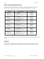
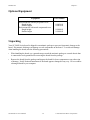

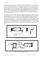


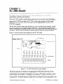
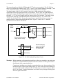
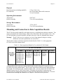
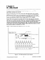
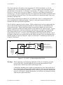


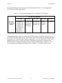

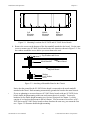

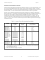
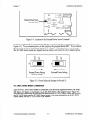

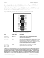

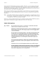

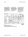


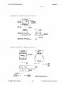

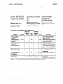
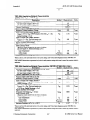
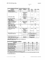
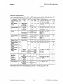
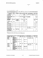

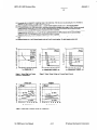
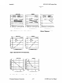
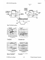
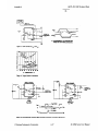
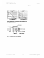

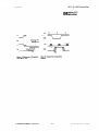

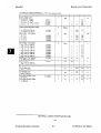
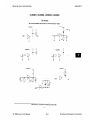
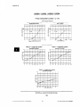

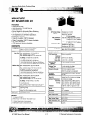
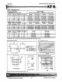

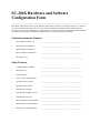
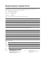
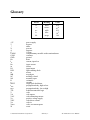
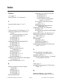


![10780-90006 - 10780A Laser Receiver for 5501A [Prefix 1948] (Mar](http://vs1.manualzilla.com/store/data/006009643_1-6e2f54ebb2199ef6df634558ba4c1bb6-150x150.png)