1
Distributed Power System SA500 Drive
Diagnostics, Troubleshooting,
and Start-Up Guidelines
Instruction Manual S-3022-1
Throughout this manual, the following notes are used to alert you to safety considerations:
!
ATTENTION: Identifies information about practices or circumstances that can lead to personal
injury or death, property damage, or economic loss.
Important: Identifies information that is critical for successful application and understanding of the product.
The thick black bar shown on the outside margin of this page will be used throughout this instruction manual to
signify new or revised text or figures.
!
ATTENTION: Only qualified personnel familiar with the construction and operation of this
equipment and the hazards involved should install, adjust, operate, or service this equipment.
Read and understand this manual and other applicable manuals in their entirety before
proceeding. Failure to observe this precaution could result in severe bodily injury or loss of life.
ATTENTION: DC bus capacitors retain hazardous voltages after input power has been
disconnected. After disconnecting input power from the DC bus supply, wait five (5) minutes and
then measure the voltage at the POS and NEG terminals of the DC bus supply and each Power
Module to ensure the DC bus capacitors are discharged before touching any internal components.
Failure to observe this precaution could result in severe bodily injury or loss of life.
ATTENTION: For brushless motor applications, changing any resolver wiring, breaking the
resolver coupling, replacing the resolver, or replacing the motor and resolver for any reason
requires that the shaft alignment test be performed again. Resolver wiring changes always affect
shaft alignment. A resolver change and/or a new motor/resolver combination will affect the shaft
alignment. Improper shaft alignment can cause motor overspeed when the motor is started. Failure
to observe this precaution could result in bodily injury.
ATTENTION: The user must provide an external, hardwired emergency stop circuit outside of the
drive circuitry. This circuit must disable the system in case of improper operation. Uncontrolled
machine operation may result if this procedure is not followed. Failure to observe this precaution
could result in bodily injury.
ATTENTION: Inserting or removing a module or its connecting cables may result in unexpected
machine motion. Turn off power to the rack before removing a module or its connecting cables.
Failure to observe these precautions could result in bodily injury.
ATTENTION: Only qualified Rockwell personnel or other trained personnel who understand the
potential hazards involved may make modifications to the rack configuration, variable
configuration, and application tasks. Any modifications may result in uncontrolled machine
operation. Failure to observe these precautions could result in damage to equipment and bodily
injury.
ATTENTION: Registers and bits in the UDC module that are described as “read only” or for “system
use only” must not be written to by the user. Writing to these registers and bits may result in
improper system operation. Failure to observe this precaution could result in bodily injury.
ATTENTION: The user is responsible for conforming with all applicable local, national, and
international codes. Failure to observe this precaution could result in damage to, or destruction
of, the equipment.
The information in this user’s manual is subject to change without notice.
AutoMax™ is a trademark of Rockwell Automation.
©1998 Rockwell International Corporation
CONTENTS
Chapter 1
Introduction
1.1 Related Publications ........................................................................................ 1-1
1.2 Typographical Conventions ............................................................................. 1-2
Chapter 2
Diagnostics and Troubleshooting
2.1 Definition of Terms Used in Diagnostics and Troubleshooting ........................ 2-1
2.2 Power-up Diagnostics in the UDC Module and PMI ........................................ 2-3
2.3 Interlock Tests ................................................................................................. 2-3
2.4 Run-time Diagnostics ...................................................................................... 2-3
2.4.1 Drive Faults ........................................................................................... 2-4
2.4.1.1 How the System Reacts to Drive Faults ................................. 2-4
2.4.1.2 MCR Output Control ............................................................... 2-5
2.4.2 Drive Warnings...................................................................................... 2-5
2.4.3 How to Clear the Drive Fault and Drive Warning Registers .................. 2-6
Chapter 3
PMI Operating Modes
3.1 Idle Mode ......................................................................................................... 3-1
3.2 PMI Run Mode................................................................................................. 3-1
3.3 Alignment Test Mode....................................................................................... 3-4
Chapter 4
Installation and Start-Up Guidelines
4.1 Using the AutoMax Programming Executive to Access the Rack ................... 4-1
4.2 Installation Requirements ................................................................................ 4-2
4.3 Installing the Motor .......................................................................................... 4-3
4.4 Installing the Drive ........................................................................................... 4-3
4.4.1 Cabinet-Enclosed Wall-Mounted Drives................................................ 4-3
4.4.2 Floor-Mounted Drives............................................................................ 4-3
4.4.3 Panel-Mounted Drives........................................................................... 4-3
4.5 Wiring the Power Module ................................................................................ 4-3
4.6 Basic Drive Interconnections ........................................................................... 4-4
4.7 Drive Inspection and Start-up Guidelines ........................................................ 4-4
4.7.1 What To Do After Unexpected Test Results ......................................... 4-5
4.7.2 Recommended Test Equipment............................................................ 4-7
4.7.3 Physically Inspecting the Equipment..................................................... 4-7
4.7.4 Physically Inspecting the Motor............................................................. 4-8
4.7.5 Checking the Installation with Power Off............................................... 4-8
4.7.6 Testing Power Modules with Power On ................................................ 4-9
4.7.7 I/O Verification..................................................................................... 4-10
4.7.7.1 Testing UDC/PMI Communication Status ............................. 4-10
4.7.7.2 Testing Rail I/O Registers ..................................................... 4-11
4.7.7.3 Testing Feedback Registers and Bits ................................... 4-12
4.7.7.4 Testing the UDC Module Test Switch Register..................... 4-13
4.7.7.5 Testing UDC Module Meter Ports ......................................... 4-14
4.7.8 Performing Uncoupled Motor Tests..................................................... 4-14
4.7.9 Running Dynamic Motor Tests ............................................................ 4-15
4.7.10 Updated Drawings and Software Listings ........................................... 4-16
Table of Contents
I
Appendix A Drive Fault Register ................................................................................................. A-1
Appendix B Drive Warning Register ............................................................................................ B-1
Appendix C Interlock Register ..................................................................................................... C-1
Appendix D Summary of UDC Module Drive Fault Indicators ..................................................... D-1
Appendix E Power Module LED Summary.................................................................................. E-1
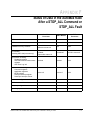
Appendix F Status of Data in the AutoMax Rack After
a STOP_ALL Command or STOP_ALL Fault .......................................................... F-1
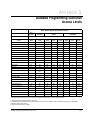
Appendix G AutoMax Programming Executive Access Levels ....................................................G-1
Index
II
...........................................................................................................................Index-1
SA500 Diagnostics, Troubleshooting, and Start-Up Guidelines
List of Figures
Figure 2.1 – PMI Operating Modes Overview........................................................... 2-2
Figure 3.1 – PMI Operating Modes and Diagnostics ................................................ 3-3
Figure 4.1 – POS and NEG Terminals on the DC Bus Supply ................................. 4-6
Table of Contents
III
IV
SA500 Diagnostics, Troubleshooting, and Start-Up Guidelines
List of Tables
Table 1.1 – SA500 Documentation (Binder S-3002) ................................................ 1-1
Table 3.1 – PMI Operating Modes............................................................................ 3-1
Table 4.1 – UDC/PMI Communication Status Register Formats............................ 4-10
Table 4.2 – Rail I/O Register Formats .................................................................... 4-11
Table 4.3 – Feedback Registers and Bits............................................................... 4-12
Table of Contents
V
VI
SA500 Diagnostics, Troubleshooting, and Start-Up Guidelines
CHAPTER 1
Introduction
This instruction manual is divided into two sections: 1) a description of SA500 drive
diagnostics and troubleshooting, 2) start-up guidelines. This manual is intended for
users of SA500 drives who have training and experience in AC drive control and who
are familiar with all other SA500 drive documentation.
The diagnostics and troubleshooting chapters (chapters 2-3) describe the error
checking built into the PMI Regulator operating system and how to use warning and
fault registers, LEDs, and the error log to diagnose drive problems.
Chapter 4 provides guidelines on starting up Distributed Power SA500 AC drives.
Although initial start-up services are usually provided by Rockwell personnel, it is
recommended that the user become familiar with the general guidelines in this chapter
in order to be better prepared to work with the Rockwell service engineer.
This manual does not describe specific applications of the standard SA500 hardware
and software. Always refer to the wiring diagrams supplied with your system for
information specific to your installation.
1.1
Related Publications
You user must become familiar with the other instruction manuals that describe the
SA500 drive system. The documentation that describes the SA500 drive is listed in
table 1.1.
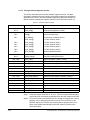
Table 1.1 – SA500 Documentation (Binder S-3002)
Document
Document Part Number
DPS Overview
S-3005
Universal Drive Controller Module
S-3007
Fiber Optic Cabling
S-3009
SA500 DC Bus Supply
S-3017
SA500 AC Power Modules
S-3018
SA500 Diagnostics, Troubleshooting, & Start-Up
Guidelines
S-3022
SA500 Information Guide
S-3024
SA500 Drive Configuration & Programming
S-3044
Additional information about using the SA500 drive is found in the prints and other
documentation shipped with each drive system. Always consult the prints and other
documents shipped with your drive system for specific information about installing,
operating, and maintaining your drive.
Introduction
1-1
1.2
Typographical Conventions
The following typographical conventions are used in this manual:
• Variable names
Variables names are shown in all capital letters followed by the appropriate
terminating character. The variable names shown in this manual are suggested
names only and may vary from the names used in your application.
Example: MCR@
• Register names
Register names are shown with the initial letters capitalized followed by the
corresponding register number for both drive A and drive B. The drive A register
number is shown first followed by the drive B register number (A/B).
Example: Drive Fault register (202/1202)
• Bit names
Individual bit names are shown with the initial letters capitalized. Also shown, in
parentheses, is the bit’s register number, bit number, and suggested variable name.
Example: Fault Reset bit (register 100/1100, bit 8, FLT_RST@)
• Parameter entry screen titles
Parameter entry screen titles and the parameters themselves are shown with the
initial letters capitalized.
Example: Feedback Data parameter entry screen
1-2
SA500 Diagnostics, Troubleshooting, and Start-Up Guidelines
CHAPTER 2
Diagnostics and Troubleshooting
The Distributed Power System contains built-in comprehensive diagnostics. In order
to diagnose and correct problems quickly, it is important to understand the types of
diagnostics that are performed, when they are performed, and how the results are
reported. This chapter describes the different types of diagnostics performed by the
system’s modules and how the results of these diagnostics are reported. This chapter
also describes how the system reacts if an error is detected.
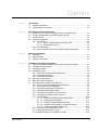
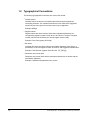
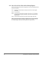
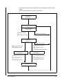
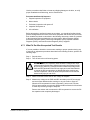
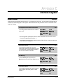
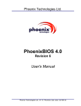
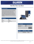
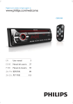
An overview of these modes is shown in figure 2.1. The Distributed Power System
provides diagnostics at each level of operation as shown in figure 3.1.
Use these figures as a reference to quickly identify the system's requirements for
entering and operating in each mode. These figures also refer to specific sections in
the manual that provide additional information.
2.1
Definition of Terms Used in Diagnostics and
Troubleshooting
For the purpose of describing diagnostics and troubleshooting, this instruction manual
will use specific terms to refer to the types of errors that can be detected by the PMI
and the response of the PMI and UDC module to those errors.
A diagnostic is a software routine specifically designed to check for error conditions.
There are three types of diagnostics in SA3100 drives: power-up diagnostics, interlock
diagnostics, and run-time diagnostics.
A drive fault is an error specifically checked for by the PMI operating system that will
shut the drive down. Faults are reported in the Drive Fault register (202/1202) of the
UDC module and in the error log for the UDC task in which the fault occurred.
A drive shut-down occurs when any fault reported in the Drive register (202/1202)
occurs.
A drive warning is an error specifically checked for by the PMI operating system that
indicates the drive is not operating in an optimum manner. Drive warnings will not
shut the drive down.
An error is any condition other than the desired condition.
Interlock diagnostics are those diagnostics performed by the PMI operating system
in response to a drive control request from the programmer, e.g., PMI_RUN@, in
register 100/1100 of the UDC module dual port memory.
Power-up diagnostics consist of the initial tests for basic functionality performed by
all printed circuit board modules.
Run-time diagnostics are those diagnostics performed continuously by the PMI as a
background task after it has received its operating system from the UDC module.
Diagnostics and Troubleshooting
2-1
POWER-UP
DIAGNOSTICS
IDLE
SELECT PMI_RUN@
OR ALN_TST@
CLOSE MCR
ALIGN RESOLVER
PMI RUN
OPEN MCR
Figure 2.1 – PMI Operating Modes Overview
2-2
SA500 Diagnostics, Troubleshooting, and Start-Up Guidelines
2.2
Power-up Diagnostics in the UDC Module and PMI
Power-up diagnostics execute in the UDC module in the AutoMax™ rack and in the
PMI in the Power Module. When power is applied to the AutoMax rack, the UDC
module performs a series of self-tests. When all of the tests are successfully
completed, the CARD OK LED on the UDC module's faceplate will turn on. If a failure
occurs, the OS OK LED will flash rapidly.
When power is applied to the Power Module, the PMI performs a series of self-tests.
When all of the tests are successfully completed, the OK LED on the Power Module’s
faceplate will turn on. If a failure occurs, the P.M. FLT LED on the Power Module will
flash rapidly.
If a UDC module or a Power Module does not pass its power-up tests, it must be
replaced. After all of the power-up tests are passed, the system continues its
power-up routine. The PMI requests the appropriate operating system from the UDC
module. The UDC module downloads the operating system and the parameter
configuration data, if available, to the PMI. The PMI then runs under the control of its
operating system and begins performing the run-time diagnostics. Run-time
diagnostics are described in section 2.4.
2.3
Interlock Tests
Interlock tests are performed by the PMI whenever one of the PMI's operating modes
is selected by the programmer through the Drive Control register (100/1100). These
diagnostics verify that all conditions required for the operating mode selected are
satisfied. If the interlock tests are completed successfully, then the operating mode
requested by the programmer can be entered. If any of the interlock diagnostics fails,
the PMI will latch a bit in the Interlock register (205/1205) corresponding to the first
diagnostic test that failed, and the requested operating mode will not be entered (i.e.,
the PMI will remain in the idle mode).
If an interlock test failure occurs, follow the procedure below:
Step 1. Reset the command bit that is currently set in the Drive Control register
(100/1100).
Step 2. Correct the condition that caused the test failure.
Step 3. Set the desired command bit in the Drive Control register (100/1100).
The PMI will perform the interlock tests each time a rising edge is detected on the
command bits. The results of subsequent interlock tests will overwrite the previous
test’s results.
2.4
Run-time Diagnostics
Run-time diagnostics are performed continuously by the PMI after its operating
system has been downloaded by the UDC module. These diagnostics test the status
of the PMI and the connected hardware and also check the integrity of the
communication link between the UDC module and the PMI.
Diagnostics and Troubleshooting
2-3
The results of the diagnostics are stored in either the Drive Warning register
(203/1203) or the Drive Fault register (202/1202) in the UDC module's dual port
memory. How drive faults and drive warnings are indicated and how they affect the
operation of the drive is described in the following sections.
2.4.1 Drive Faults
When the PMI detects any of the conditions identified in the Drive Fault register, it will
shut down the drive as described below. To determine the cause of a drive shutdown,
the following indicators are provided:
• Drive Fault register (202/1202)
The PMI will set a bit in the Drive Fault register to indicate the condition that caused
the shutdown. The interlock tests check this register for fault conditions that have
occurred. Refer to Appendix A for a complete description of the Drive Fault Register.
• Drive Status Register (200/1200)
The PMI will set the Fault Detected bit (bit 8, FLT@) of the Drive Status register when
a drive fault has been detected.
• LEDs on the UDC module
If either LED (DRV FLT A or DRV FLT B) is on, a drive fault has been detected for the
drive using that communication channel.
• LEDs on the Power Module
The Power Module’s faceplate contains 15 status/fault LED board. Refer to Appendix
E for LED definitions.
• Error log for the UDC task
The error log for the task in which the fault occurred is accessed through the ON LINE
menu of the AutoMax Programming Executive. A list of the drive fault error codes can
be found in Appendix D. Refer to appropriate AutoMax Programming Executive
instruction manual for more information regarding the Programming Executive and the
ON LINE menu.
2.4.1.1 How the System Reacts to Drive Faults
As described in section 2.4.1, if the PMI detects any of the conditions identified by the
Drive Fault register, it will shut down the drive. This means that the PMI responds by
immediately disabling the gates of the power devices, causing the motor to begin a
coast-to-rest stop. The PMI will wait 100 msec after the fault before turning off the
MCR output.
Note that the UDC task is not stopped automatically is a drive fault causes a
shut-down of the drive. The user must ensure that the application task(s) test the
Drive Fault register (202/1202) and takes any appropriate action if a fault is detected.
2-4
SA500 Diagnostics, Troubleshooting, and Start-Up Guidelines
2.4.1.2 MCR Output Control
The MCR output on the Power Module is used to control an output contactor. This
output contactor, sometimes referred to as an M-contactor, disconnects power from
the motor. This option is selected during UDC module parameter configuration. If the
programmer selects to connect the MCR output to an output contactor, auxiliary
contacts from this device must be wired to the AUX IN1/MFDBK input as feedback.
The PMI operating system will wait for AUX IN1/MFDBK to turn on before executing
any operating mode.
The Run Permissive input (RPI) on the Power Module and the MCR output are
interlocked in hardware. The MCR output can be turned on only when the RPI is
asserted. The MCR output itself is under the control of the PMI. Application tasks
have no direct control of the MCR output. RPI is controlled by the user. When RPI is
off, MCR cannot be activated.
The following conditions will cause the MCR output to turn off:
• Absence of the RPI signal
• Occurrence of a drive fault
• Control algorithm is turned off (PMI_RUN@ = 0)
When any of the above conditions occurs, the PMI will disable the power device gates
and the motor will begin a coast-to-rest stop. The PMI will wait 100 msec and then turn
off the MCR output.
In addition, if the RPI signal is removed, the MCR output and gate power will be
removed under hardware control within approximately 0.5 seconds of the removal of
the RPI signal to provide an additional interlock. This is done regardless of the actions
taken by the PMI.
2.4.2 Drive Warnings
The PMI will check for conditions that are not serious enough to shut down the drive,
but may affect its performance. If the PMI detects any of the conditions described in
the Drive Warning register, it will set the appropriate bit but will NOT shut down the
drive. The user must ensure that the application task tests the Drive Warning register
(203/1203) and takes any appropriate action if a warning condition is detected.
The PMI will also set the Warning Detected bit (register 200/1200, bit 9, WRN@) if a
drive warning has been detected.
Appendix B provides a complete description of the Drive Warning register. Except for
rail faults, drive warnings are not indicated by LEDs (a rail fault will turn on the RAIL
FLT LED on the Power Module). Drive warnings are not displayed in the UDC task's
error log.
Diagnostics and Troubleshooting
2-5
2.4.3 How to Clear the Drive Fault and Drive Warning Registers
After a drive fault has been detected, the programmer must do the following before the
drive can be restarted:
Step 1. Reset the command bit that is currently set in the Drive Control register
(100/1100).
Step 2. Correct the fault.
Step 3. Set and reset the Fault Reset bit (register 100/1100, bit 8, FLT_RST@) to
clear the Drive Fault register (200/1200). (Note that the Fault Reset bit is
edge sensitive.)
Step 4. Set the desired command bit in the Drive Control register (100/1100).
After a drive warning has been detected, the programmer can clear the entire Drive
Warning register by setting and resetting the Warning Reset bit (register 100/1100,
bit 9, WRN_RST@). (Note that the Warning Reset bit is edge sensitive.)
2-6
SA500 Diagnostics, Troubleshooting, and Start-Up Guidelines
CHAPTER 3
PMI Operating Modes
The PMI's default operating mode is idle. All other operating modes are selected by
the programmer in the Drive Control register (100/1100). Table 3.1 shows the available
operating modes. Note that the operating modes are mutually exclusive, i.e., only one
mode may be enabled at a time (this is checked by the interlock tests).
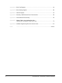
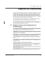
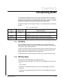
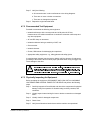
The PMI's operating modes are shown in figure 3.1 and are described in the following
sections.
Table 3.1 – PMI Operating Modes
Operating
Mode
Drive Control
Register Bit
Idle
N/A
PMI Run
0
Executes the torque, speed, or position control algorithm.
Alignment Test
1
Enables the resolver alignment procedure for brushless drives.
3.1
Mode Description
The PMI’s default operating mode during which no algorithms are
running.
Idle Mode
The PMI's default operating mode after passing the power-up diagnostics is idle.
When in idle mode, the PMI is waiting for a command from the Drive Control register
(100/1100) to change operating modes.
In order for the PMI to enter the requested operating mode, the Interlock tests must be
passed. If any of the Interlock tests fails, or if any fault is latched in the Drive Fault
register (202/1202), the PMI will remain in the idle mode.
The PMI will return to the idle mode when it exits any of the other operating modes.
3.2
PMI Run Mode
To execute the control algorithm(s), the programmer sets:
• the PMI Run Enable bit (register 100/1100, bit 0, PMI_RUN@) for the torque minor
loop
and, if required,
• the Speed Loop Enable bit (register 100/1100, bit 3, SPD_ON@) for the speed
minor loop
• the Position Loop Enable bit (register 100/1100, bit 4, POS_ON@) for the position
minor loop.
PMI Operating Modes
3-1
Before the control algorithm(s) can be executed, all of the following conditions must be
met:
• The interlock tests, register 205/1205, must be passed successfully. See
section 2.3.
• The M-contactor must be closed, if configured. See section 2.4.1.2.
• The UDC task in the AutoMax rack must be running. The status of the UDC task is
indicated by the UDC Task Running bit (register 100/1100, bit 15, UDC_RUN@).
If any of these requirements are not met or if a fault is latched in the Drive Fault
register (202/1202), the PMI will remain in the idle mode.
If these requirements are met, the PMI will execute the torque minor loop, and if
selected, the speed and position minor loops. At this time, the PMI will set the PMI On
bit (200/1200, bit 0, PMI_ON@) to indicate that the torque minor loop is executing.
Important: Note that if a brushless motor is being used, the resolver and rotor shafts
must be aligned before the torque minor loop is executed or the motor
may not run properly. This is not tested by the Interlock tests as a
requirement to enter the PMI run mode. See section 3.3 for description of
this procedure.
The torque minor loop executes until one of the following occurs:
• The PMI Run Enable bit (register 100/1100, bit 0, PMI_RUN@) is reset by the
application task.
• A drive fault is detected. Refer to Appendix A for a description of the Drive Fault
register.
• The RPI signal (register 201/1201, bit 0) is removed.
The speed minor loop executes until one of the following occurs:
• The Speed Loop Enable bit (register 100/1100, bit 3, SPD_ON@) is reset by the
application task.
• The PMI Run Enable bit (register 100/1100, bit 0, PMI_RUN@) is reset by the
application task.
• A drive fault is detected. Refer to Appendix A for a description of the Drive Fault
register.
• The RPI signal (register 201/1201, bit 0) is removed.
The position minor loop executes until one of the following occurs:
• The Position Loop Enable bit (register 100/1100, bit 4, POS_ON@) is reset by the
application task.
• The Speed Loop Enable bit (register 100/1100, bit 3, SPD_ON@) is reset by the
application task.
• The PMI Run Enable bit (register 100/1100, bit 0, PMI_RUN@) is reset by the
application task.
3-2
SA500 Diagnostics, Troubleshooting, and Start-Up Guidelines
• A drive fault is detected. Refer to Appendix A for a description of the Drive Fault
register.
• The RPI signal (register 201/1201, bit 0) is removed.
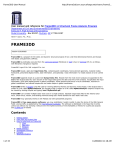
POWER-UP
DIAGNOSTICS
SECTION 2.2
IDLE
SECTION 3.1
SELECT PMI_RUN@
or ALN_TST@
INTERLOCK TESTS OK
and
PMI_RUN@ OR ALN_TST@
INTERLOCK TESTS FAILED
CLOSE MCR
SECTION 2.4.1.2
MCR DID NOT CLOSE
MCR CLOSED or NOT USED
and
ALN_TST@ REG 100 BIT 2
and
CONFIGURED FOR BRUSHLESS DC
MCR CLOSED or NOT USED
and
PMI_RUN@ REG 100 BIT 0
PMI RUN
SECTION 3.2
ALIGN RESOLVER
SECTION 3.3
ALN_TST@ OFF REG 100 BIT 1
or
FAULT PRESENT REG 202
or
RPI MISSING REG 201 BIT 0
PMI_RUN@ OFF REG 100 BIT 0
or
FAULT PRESENT REG 202
or
RPI MISSING REG 201 BIT 0
OPEN MCR
SECTION 2.4.1.2
Figure 3.1 – PMI Operating Modes and Diagnostics
PMI Operating Modes
3-3
3.3
Alignment Test Mode
For SA500 drives controlling brushless DC motors, the resolver shaft and the rotor
shaft must be aligned in order to ensure that maximum torque is generated. Therefore,
an alignment procedure must be performed before the torque, speed, and position
minor loops are executed. The alignment procedure automatically determines the
offset required to bring the rotor and the stator fields 90° apart. This procedure must
be performed whenever the resolver has been disconnected from the motor for any
reason, including reversing cosine leads to the resolver.
!
ATTENTION: For brushless motor applications, changing any resolver
wiring, breaking the resolver coupling, replacing the resolver, or replacing
the motor and resolver for any reason requires that the shaft alignment
test be performed again. Resolver wiring changes always affect shaft
alignment. A resolver change and/or a new motor/resolver combination
will affect the shaft alignment. Improper shaft alignment can cause motor
overspeed when the motor is started. Failure to observe this precaution
could result in bodily injury.
Important: This procedure will cause the motor to move less than one revolution in
both forward and reverse direction for under three minutes. Uncouple the
motor from the load to run this test if this motion would be harmful to your
machine.
The programmer sets the Enable Resolver Alignment Test bit (register 100/1100, bit 1,
ALN_TST@) to request the PMI to execute the alignment procedure. Before the
alignment test can be executed, all of the following conditions are required:
• The interlock tests (described in section 2.3) must be passed successfully.
• The M-contactor, if configured, must be closed (described in section 2.4.1.2).
If any of the requirements are not met of if a fault is latched in the Drive Fault register
(202/1202), the PMI will remain in the idle mode.
If these requirements are met, the PMI will execute the alignment procedure.
When the alignment procedure is successfully completed, the PMI will set the
Alignment OK bit (register 200/1200, bit 1, ALN_OK@). The programmer can then
turn off the Enable Resolver Alignment Test bit. This will also turn off the Alignment
OK bit. The result of this test is written to the tunable variable RES_ALN% by the PMI.
If a problem is detected during the alignment procedure (e.g., the incorrect number of
motor poles or resolver type was entered during configuration), the Tuning Aborted
Warning bit (register 203/1203, bit 5, WRN_TUN@) is set. When the alignment
procedure is turned off, the PMI returns to the idle state.
3-4
SA500 Diagnostics, Troubleshooting, and Start-Up Guidelines
CHAPTER 4
Installation and Start-Up Guidelines
$77(17,21 2QO\
!
TXDOLILHG SHUVRQQHO IDPLOLDU ZLWK WKH FRQVWUXFWLRQ DQG
RSHUDWLRQ RI WKLV HTXLSPHQW DQG WKH KD]DUGV LQYROYHG VKRXOG LQVWDOO
DGMXVW RSHUDWH RU VHUYLFH WKLV HTXLSPHQW 5HDG DQG XQGHUVWDQG WKLV
PDQXDO DQG RWKHU DSSOLFDEOH PDQXDOV LQ WKHLU HQWLUHW\ EHIRUH SURFHHGLQJ
)DLOXUH WR REVHUYH WKLV SUHFDXWLRQ FRXOG UHVXOW LQ VHYHUH ERGLO\ LQMXU\ RU
ORVV RI OLIH
$77(17,21 7KH
XVHU LV UHVSRQVLEOH IRU FRQIRUPLQJ ZLWK DOO DSSOLFDEOH
ORFDO QDWLRQDO DQG LQWHUQDWLRQDO FRGHV )DLOXUH WR REVHUYH WKLV SUHFDXWLRQ
FRXOG UHVXOW LQ GDPDJH WR RU GHVWUXFWLRQ RI WKH HTXLSPHQW
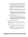
This section describes general guidelines that should be followed when verifying the
correct installation of the drive hardware and in performing the drive start-up. For more
information regarding installation guidelines, refer to instruction manual D2-3115
(Installing, Operating, and Maintaining Engineered Drive Systems).
As part of the start-up procedure, the AutoMax Programming Executive software is
used to verify the status of drive I/O and to make drive adjustments. Section 4.1
describes some of the restrictions imposed by the AutoMax Programming Executive
software.
4.1
Using the AutoMax Programming Executive to
Access the Rack
The AutoMax Programming Executive enables four users to access and work in the
same rack simultaneously. However, certain restrictions exist when more than one
user is working in a rack.
• The maximum number of users is four (4) per rack (one user connected directly to
the rack and three users connected via the DCS/AutoMax Network, or four users
connected via the DCS/AutoMax Network).
• Data access is required for the user to Set/Force COMMON variables. All users
must assure that variable values are not written over by other users working in the
rack.
• Task access is required for the user to load a single task and to Set/Tune/Force
LOCAL variables in a task. Only one user will be granted Task access for each task
in the rack.
• Rack access is required to load the rack configuration and to load all application
tasks (AutoMax tasks and UDC tasks).
• If a user has Rack access, no other user can make changes in that rack. All other
users will be limited to monitoring tasks and variables.
Installation and Start-Up Guidelines
4-1
• Each user can monitor up to 16 COMMON and/or LOCAL variables.
• A maximum of 32 LOCAL variables per UDC module can be monitored, regardless
of the number of users.
• A maximum of 16 variables per rack can be forced.
Appendix G describes the type of access required by the user in order to carry out
common Programming Executive operations. Refer to the AutoMax Programming
Executive instruction manual for more specific information.
4.2
Installation Requirements
The installation must meet the following requirements:
Ambient Temperature
• Power Modules: 0 to 60° C (32 to 140° F)
Cooling
• Air for cooling must be of sufficient quality and flow to avoid recycling the heated
exhaust air back into the drive air inlets.
Relative humidity
• 5 - 95%, non-condensing
Altitude
• Maximum 1000 meters (3300 feet) above sea level.
Refer to instruction manual S-3018 for derating information when operating above
1000 meters.
Air Quality
• Clean
No flammable vapors, chemical fumes, or oil vapor.
Clearances
• Must allow access to the equipment within the cabinet for inspection, maintenance,
and replacement.
• Must provide non-restricted air flow to and from the intake and exhaust openings.
See the following instruction manuals for more detailed information about installation
requirements:
4-2
• S-3018
SA500 Power Modules
• S-3017
SA500 DC Bus Supplies
SA500 Diagnostics, Troubleshooting, and Start-Up Guidelines
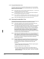
4.3
Installing the Motor
The motor should be installed in accordance with its own installation instructions.
Refer to the instruction manual that was provided for the motor (in the Instruction
Book) for specific instructions.
4.4
Installing the Drive
The drive is most often supplied in its own NEMA 1 enclosure. It is also available in
NEMA 4 and NEMA 12 cabinets, in free standing floor-mounted cabinets, in an open
panel configuration for mounting in the customer’s enclosure, or in a custom-built
control room.
4.4.1 Cabinet-Enclosed Wall-Mounted Drives
The drive in a wall-mounted NEMA 1 enclosure is force ventilated by means of its own
internal cooling fan(s) and additional cabinet fans. Air is drawn into the enclosure
through slots in the cabinet bottom and in the lower portion of the cabinet sides. Air is
forced out through internally shielded slots near the top of the cabinet sides. Air intake
and exhaust openings are unfiltered.
NEMA 4 and NEMA 12 cabinet enclosures are unventilated. Although an internal
circulating fan is employed to move air around within the confines of the cabinet to
better utilize the cabinet skin for heat dissipation and reduce internal hot spots, there
is no air exchange with the atmosphere outside of the enclosure.
4.4.2 Floor-Mounted Drives
NEMA 1 free-standing floor-mounted cabinets draw cooling air from slots in the lower
portion of the cabinet door and force air through slots near the door’s top, if a cabinet
fan is supplied. NEMA 4 and NEMA 12 floor-mounted cabinet enclosures are
unventilated.
4.4.3 Panel-Mounted Drives
The drive is available as a panel-mounted assembly where mounting of the drive
within a customer-supplied enclosure is desired. In these instances, the user is
responsible for ensuring that the maximum temperature within this enclosure remains
at or below the rated ambient temperature under worst-case operating conditions.
Note that the same fan-cooling as described in the previous two sections will be
provided for the Power Module.
4.5
Wiring the Power Module
Verify that the input power to the DC bus supply is of the correct voltage and sufficient
ampacity to support the Power Module’s input current requirements. Note that the
maximum available current from the DC bus supply must be less than the Power
Module’s short circuit current rating (RMS). Refer to the drive cabinet and motor
nameplates for correct current ratings and input power information.
Installation and Start-Up Guidelines
4-3
4.6
Basic Drive Interconnections
$77(17,21 ,I
!
\RXU GULYH FDELQHW LV PRXQWHG LQ VXFK D ZD\ WKDW WKH
FDELQHW LWVHOI LV QRW JURXQGHG D JURXQG ZLUH PXVW EH FRQQHFWHG WR WKH
GULYH FDELQHW WR SURYLGH VDIHW\ IRU SHUVRQQHO $OVR WKH PRWRU IUDPH VKRXOG
EH JURXQGHG E\ VROLGO\ FRQQHFWLQJ D JURXQG ZLUH WR D VFUHZ LQ WKH FRQGXLW
ER[ )DLOXUH WR REVHUYH WKHVH SUHFDXWLRQV FRXOG UHVXOW LQ VHYHUH ERGLO\
LQMXU\ RU ORVV RI OLIH
$77(17,21 7KH
XVHU LV UHVSRQVLEOH IRU FRQIRUPLQJ ZLWK DOO DSSOLFDEOH
ORFDO QDWLRQDO DQG LQWHUQDWLRQDO FRGHV )DLOXUH WR REVHUYH WKLV
SUHFDXWLRQV FRXOG UHVXOW LQ GDPDJH WR RU GHVWUXFWLRQ RI WKH HTXLSPHQW
The SA500 drive requires interconnecting wiring per applicable codes between the
drive and the following:
• motor
• operator’s control station (if used)
• resolver
• UDC module
• earth ground
Refer to the Elementary Diagram (W/E) (and the Interconnection Diagram (W/I) if
provided) supplied with your drive for these interconnections. Be sure that the W/E
number corresponds to that on the drive’s cabinet or Power Module nameplate. All
interconnecting wiring must be sized and installed in conformance with the National
Electrical Code and applicable local or other codes.
Unless a standard pre-built fiber-optic cable was included with your system, the
fiber-optic cabling that links the UDC module(s) in the AutoMax rack with the Power
Module(s) containing the PMI(s) must be installed by someone experienced in
installing fiber-optic cables. Unless you have in-house expertise in installing fiber-optic
cable, it is recommended that you contact an experienced contractor to perform the
installation. Information regarding the selection and installation of fiber-optic cabling is
contained in the Distributed Power System Fiber-Optic Cabling instruction manual
(S-3009).
4.7
Drive Inspection and Start-up Guidelines
$77(17,21 2QO\
!
TXDOLILHG SHUVRQQHO IDPLOLDU ZLWK WKH FRQVWUXFWLRQ DQG
RSHUDWLRQ RI WKLV HTXLSPHQW DQG WKH KD]DUGV LQYROYHG VKRXOG LQVWDOO
DGMXVW RSHUDWH RU VHUYLFH WKLV HTXLSPHQW 5HDG DQG XQGHUVWDQG WKLV
PDQXDO DQG RWKHU DSSOLFDEOH PDQXDOV LQ WKHLU HQWLUHW\ EHIRUH SURFHHGLQJ
)DLOXUH WR REVHUYH WKLV SUHFDXWLRQ FRXOG UHVXOW LQ VHYHUH ERGLO\ LQMXU\ RU
ORVV RI OLIH
DC bus capacitors retain hazardous voltages after input
power has been disconnected. After disconnecting input power from the
DC bus supply, wait five (5) minutes and then measure the voltage at the
POS and NEG terminals of the DC bus supply and each Power Module
to ensure the DC bus capacitors are discharged before touching any
internal components. Failure to observe this precaution could result in
severe bodily injury or loss of life.
$77(17,21
4-4
SA500 Diagnostics, Troubleshooting, and Start-Up Guidelines
Use the procedures that follow to locate any shipping damage to the drive, to verify
proper installation and field wiring, and to start the drive.
Recommended Start-Up Sequence
1. Physical inspection of equipment
2. Motor checks
3. Preliminary inspection with power off
4. Inspection with power on
5. I/O verification
Before attempting to perform this start-up procedure, you should be familiar with the
general arrangement and function of the drive equipment and should verify that it has
been installed and wired as described in the following documents, which are included
in the Instruction Book provided with your drive system: Wiring Diagrams (W/Ds),
Elementary Diagrams (W/Es), Panel Layout Diagrams (W/Ls), Operator's Station
Diagrams (W/Os), and Interconnection Diagrams (W/Is) if supplied.
4.7.1 What To Do After Unexpected Test Results
If it is not possible to obtain the correct meter reading or proper operation during any
of the tests or adjustment procedures described in the following sections, perform the
following steps:
Step 1. Stop the drive.
Step 2. Turn off and lock out all incoming power.
DC bus capacitors retain hazardous voltages after input
power has been disconnected. After disconnecting input power from the
DC bus supply, wait five (5) minutes and then measure the voltage at the
POS and NEG terminals of the DC bus supply and each Power Module
to ensure the DC bus capacitors are discharged before touching any
internal components. Failure to observe this precaution could result in
severe bodily injury or loss of life.
$77(17,21
!
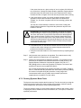
Step 3. Wait five minutes to allow the DC bus voltage to dissipate.
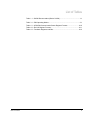
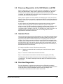
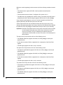
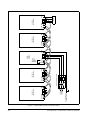
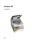
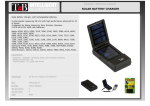
Step 4. Measure the voltage at the POS and NEG terminals on the DC bus supply
and each Power Module before working on any unit. Refer to figure 4.1.
When the DC bus potential is down to less than 5 volts, touch a 50 ohm,
50 W or larger resistor to each unit’s POS and NEG terminals for 20 seconds
to allow any remaining voltage to dissipate.
Remove the resistor and re-measure the DC bus potential to ensure the DC
bus capacitors are completely discharged.
Installation and Start-Up Guidelines
4-5
Figure 4.1 – POS and NEG Terminals on the DC Bus Supply
4-6
SA500 Diagnostics, Troubleshooting, and Start-Up Guidelines
To grounding rod
or Building Steel
POS NEG
U V W
SA500 AC
Power Module
Fuse
Fuse
Fuse
Fuse Disconnecting Switch
GND
PE
U V W
AC Input
Voltage
(3-Phase)
POS NEG
SA500 AC
Power Module
GND
POS NEG
Measure
DC Bus
Voltage
Here
L1 L2 L3
SA500
DC Bus
Supply
GND
POS NEG
U V W
SA500 AC
Power Module
GND
POS NEG
Motor
U V W
SA500 AC
Power Module
GND
Step 5. Verify the following:
a. All connections are in strict conformance to the wiring diagrams.
b. There are no loose or broken connections.
c. There are no damaged components.
Step 6. Repeat the original test that failed.
4.7.2 Recommended Test Equipment
Rockwell recommends the following test equipment:
• Isolated oscilloscope with a current probe and x100 probe for DC bus
measurements. An isolation transformer is needed to isolate the oscilloscope and
any other equipment.
• AC and DC clamp-on ammeters
• Isolated multimeter having a sensitivity of 20KΩ/volt
• Chart recorder
• Isolated voltmeter
• 50 ohm, 50W resistor for discharging bus capacitors
• Appropriate safety equipment, e.g., safety glasses and safety gloves
A megohmmeter (megger) may be used to reliably verify the absence of inadvertent
grounding of the motor. Failure to follow proper procedure when using a megger may
cause damage to the drive.
$77(17,21 ,I
!
D PHJRKPPHWHU LV XVHG GLVFRQQHFW DOO OHDGV EHWZHHQ
WKH URWDWLQJ HTXLSPHQW DQG WKH GULYH FDELQHW 7KLV ZLOO SUHYHQW GDPDJH
WR HOHFWURQLF FLUFXLWU\ 3RZHU 0RGXOHV DQG WKHLU DVVRFLDWHG FLUFXLWV HWF
GXH WR WKH KLJK YROWDJH JHQHUDWHG E\ WKH PHJJHU )DLOXUH WR REVHUYH WKLV
SUHFDXWLRQ FRXOG UHVXOW LQ GDPDJH WR RU GHVWUXFWLRQ RI WKH HTXLSPHQW
4.7.3 Physically Inspecting the Equipment
Before operating the equipment, DISCONNECT AND LOCK OUT ALL INCOMING
LINE POWER AND CONTROL POWER TO THE DRIVE and perform the following
steps:
Step 1. Carefully inspect the Power Module and other drive components for physical
damage. Verify free operation of all switch relays, auxiliary contacts, and
contactors.
Step 2. Visually inspect internal wiring for loose or broken connections or damaged
wires.
Step 3. Visually check for damaged components.
Step 4. Check fuses.
Step 5. Verify that all shutdown interlocks around the machine are operational.
Installation and Start-Up Guidelines
4-7
4.7.4 Physically Inspecting the Motor
Carefully read and understand the instruction manual that describes your motor. Then
make the following motor inspection. Refer to section 4.7.1, What to Do After
Unexpected Test Results, for more information.:
Step 1. Disconnect and lockout all incoming line power and control power to the
drive.
Step 2. Check that the motor is installed according to the motor’s instruction manual.
Step 3. If possible, uncouple the motor from the driven machinery.
Step 4. Rotate the motor shaft by hand to check that the motor is free from any
binding or mechanical load problem.
Step 5. Check that no loose items such as shaft keys, couplings, etc., are present.
Step 6. Check all connections for tightness and proper insulation.
Step 7. Check that the interior of the motor is clean and dry.
$77(17,21 %HIRUH
!
VWDUWLQJ WKH PRWRU UHPRYH DOO XQXVHG VKDIW NH\V
DQG ORRVH URWDWLQJ SDUWV WR SUHYHQW WKHP IURP IO\LQJ RII 5HSODFH DOO FRYHUV
DQG SURWHFWLYH GHYLFHV )DLOXUH WR REVHUYH WKHVH SUHFDXWLRQV FRXOG UHVXOW
LQ GDPDJH WR HTXLSPHQW DQG ERGLO\ LQMXU\
4.7.5 Checking the Installation with Power Off
Perform the following tests to verify that:
• Correct power is being supplied to the drive
• Wiring has been done properly
• There are no grounds in the magnetic control circuits or rotating equipment
• All safety devices are in place and functional.
Step 1. If the drive is powered up, disconnect and lock out all incoming line power
and control power to the drive. Refer to section 4.7.1 for additional
information on measuring and discharging DC bus voltage.
If the drive is not under power, proceed to step 2.
DC bus capacitors retain hazardous voltages after input
power has been disconnected. After disconnecting input power from the
DC bus supply, wait five (5) minutes and then measure the voltage at the
POS and NEG terminals of the DC bus supply and each Power Module
to ensure the DC bus capacitors are discharged before touching any
internal components. Failure to observe this precaution could result in
severe bodily injury or loss of life.
$77(17,21
!
Step 2. Visually check that the AC supply to the DC bus supply is of the correct
voltage and frequency and that the plant supply branch from which the drive
is to be operated is of sufficient ampacity to supply drive input current
requirements.
4-8
SA500 Diagnostics, Troubleshooting, and Start-Up Guidelines
Step 3. Verify that all drive components have been properly installed and interwired
per the instructions provided in the wiring diagrams (W/Ds, W/Es, W/Ls,
W/Os, and W/Is).
Step 4. Rotate the 1/4 turn cover fasteners securing the Power Module cover.
Remove the cover. Inspect the Power Module for cables that may have come
loose during shipping. Replace and re-secure the Power Module cover.
Step 5. Check for grounds in the magnetic control circuits. Always use an ohmmeter
to check for grounds in resolver circuits.
Step 6. Check rotating equipment for grounds.
Step 7. Check for tight connections on all wiring.
Step 8. Check circuit breaker trip settings.
Step 9. Verify that all safety devices are in place.
Step 10. Check fuses.
4.7.6 Testing Power Modules with Power On
$77(17,21 2QO\
!
TXDOLILHG SHUVRQQHO IDPLOLDU ZLWK WKH FRQVWUXFWLRQ DQG
RSHUDWLRQ RI WKLV HTXLSPHQW DQG WKH KD]DUGV LQYROYHG VKRXOG LQVWDOO
DGMXVW RSHUDWH RU VHUYLFH WKLV HTXLSPHQW 5HDG DQG XQGHUVWDQG WKLV
PDQXDO DQG RWKHU DSSOLFDEOH PDQXDOV LQ WKHLU HQWLUHW\ EHIRUH SURFHHGLQJ
)DLOXUH WR REVHUYH WKLV SUHFDXWLRQ FRXOG UHVXOW LQ VHYHUH ERGLO\ LQMXU\ RU
ORVV RI OLIH
$77(17,21 7KLV
SURFHGXUH LV SHUIRUPHG ZLWK SRZHU RQ ([HUFLVH
H[WUHPH FDXWLRQ DV KD]DUGRXV YROWDJH H[LVWV )DLOXUH WR REVHUYH WKLV
SUHFDXWLRQ FRXOG UHVXOW LQ VHYHUH ERGLO\ LQMXU\ RU ORVV RI OLIH
$77(17,21 %HIRUH
SURFHHGLQJ PDNH VXUH WKDW \RX FDQ TXLFNO\ VWRS
WKH GULYH LI QHFHVVDU\ ,I WKH LQSXW SRZHU GLVFRQQHFW DQGRU VWRS
SXVKEXWWRQ DUH RXW RI \RXU UHDFK KDYH DQ DVVRFLDWH VWDWLRQHG WR RSHUDWH
WKHP LQ WKH HYHQW RI GULYH PDOIXQFWLRQ GXULQJ WKHVH LQLWLDO SRZHU FKHFNV
DQG GULYH DGMXVWPHQW )DLOXUH WR REVHUYH WKLV SUHFDXWLRQ FRXOG UHVXOW LQ
GDPDJH WR HTXLSPHQW DQG ERGLO\ LQMXU\
The following steps are required to test SA500 Power Modules before they can be put
into service.
Perform the following steps before attempting to start the drive:
Step 1. Check the DC bus supply’s DC power levels.
a. Verify that DC input power to the Power Module is off.
b. Connect a DC voltmeter to the POS and NEG terminals on the Power
Module.
c. Apply power to the drive and verify that the DC voltage level is correct.
Step 2. If the motor uses 3-phase AC to power its blower motor, verify proper blower
motor rotation. Check to see that air is being forced into the motor. If air flow
is reversed (air is being pulled out of the motor), remove AC input power from
the blower motor and interchange any two AC line power wires feeding the
blower motor. Note that the blower motor must be wired to a fixed AC power
source and not to the Power Module.
Installation and Start-Up Guidelines
4-9
4.7.7 I/O Verification
I/O verification consists of ensuring that all physical I/O is properly connected and
functional, and that all critical registers and bits can be accessed in the UDC dual port
memory. Before verifying the I/O, ensure that the following have been loaded to the
AutoMax rack. Note that the application tasks should not be put into run before you
have verified all I/O.
• AutoMax Processor and UDC operating systems
• Rack configuration
• Drive parameters
• All application tasks
The procedures described in the following sections are performed using the Monitor
I/O function in the AutoMax Programming Executive software.
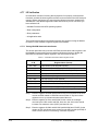
4.7.7.1 Testing UDC/PMI Communication Status
This section describes how to test the UDC/PMI communication status registers. Use
the AutoMax Programming Executive software I/O Monitor function to display the
UDC/PMI Communication Status registers in the format listed in table 4.1.
Table 4.1 – UDC/PMI Communication Status Register Formats
Drive
A/B
Register Name (format)
80 / 1080
UDC Module Ports A/B Status (binary)
81 / 1081
UDC Module Ports A/B Receive Count (decimal)
82 / 1082
UDC Module Ports A/B CRC Error Count (decimal)
83 / 1083
UDC Module Ports A/B Format Error Count (decimal)
84 / 1084
PMI A/B Status (binary)
85 / 1085
PMI A/B Receive Count (decimal)
86 / 1086
PMI A/B CRC Error Count (decimal)
87 / 1087
PMI A/B Format Error Count (decimal)
88 / 1088
UDC Module Ports A/B Fiber-Optic Link Status (hexadecimal)
89 / 1089
UDC Module Ports A/B Transmitted Message Count (decimal)
Step 1. Examine registers 80/1080 and 84/1084 for any errors reported to the UDC
module and PMI related to UDC/PMI communication. If any bits in these
registers are on, try to determine what caused the error.
Step 2. Examine registers 81/1081 and 85/1085 for the number of messages
received by the UDC module and PMI. Over time, this 16-bit value should
increase to its maximum value (32767) and then roll over.
Step 3. Examine registers 82/1082 and 83/1083 (and 86/1086 and 87/1087) for the
number of CRC and format errors received on the UDC module (and PMI). If
either of these values is incrementing, it indicates a problem.
4-10
SA500 Diagnostics, Troubleshooting, and Start-Up Guidelines
Step 4. Examine register 88/1088 for the status of the fiber-optic ports on the UDC
module. If the operating systems are loaded and no tasks are running, the
lower byte should be equal to xx03H (UDC module and PMI are exchanging
data). The upper byte should be equal to 02xxH (communication between the
UDC module and PMI is unsynchronized). Note that “xx” in the byte
descriptions indicates “not used.”
Step 5. Examine register 89/1089 for the number of messages transmitted by the
UDC module. Over time, this 16-bit value should increase to its maximum
value (32767) and then roll over.
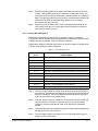
4.7.7.2 Testing Rail I/O Registers
This section describes how to test the rail I/O registers if used in your system
configuration. Use the AutoMax Programming Executive software I/O Monitor function
to display the Rail I/O registers in the format listed in table 4.2.
Display these registers in decimal format if they are used for analog I/O. Display them
in binary format if they are used for digital I/O.
Table 4.2 – Rail I/O Register Formats
Drive
A/B
Register Name
0 / 12
PMI Port 0, Channel 0
1 / 13
PMI Port 0, Channel 1
2 / 14
PMI Port 0, Channel 2
3 / 15
PMI Port 0, Channel 3
4 / 16
PMI Port 0, Faults (display in binary format)
5 / 17
PMI Port 0, Check Bit Fault Counter (display in decimal format)
6 / 18
PMI Port 1, Channel 0
7 / 19
PMI Port 1, Channel 1
8 / 20
PMI Port 1, Channel 2
9 / 21
PMI Port 1, Channel 3
10 / 22
PMI Port 1, Faults (display in binary format)
11 / 23
PMI Port 1, Check Bit Fault Counter (display in decimal format)
Step 1. Test each analog current or voltage output channel being used by writing a
value between 0 and 4095 to the appropriate register and measuring with an
ammeter or voltmeter to verify the signal on the terminal points (4-20mA or
0-10V) is proportional to the register value.
Step 2. Test each analog current or voltage input channel being used by measuring
with an ammeter or voltmeter to verify the signal on the terminal points
(4-20mA or 0-10V) is proportional to the value displayed in appropriate
register.
Step 3. Test each digital input by initiating the input and verifying that the appropriate
bit (displayed on the screen) turns on.
Step 4. Test each digital output by forcing the bit on and verifying that the signal is
present on the terminal points.
Installation and Start-Up Guidelines
4-11
4.7.7.3 Testing Feedback Registers and Bits
This section describes how to test the feedback registers and bits. Feedback
information provided by the fault, warning, and interlock registers is described in
Appendices A, B, and C. Use the AutoMax Programming Executive software I/O
Monitor function to display the registers and bits in the format listed in table 4.3.
Table 4.3 – Feedback Registers and Bits
Drive A/B
200 / 1200
Bit 15
Variable Name
(PMI_OK@)
201 / 1201
Description
Drive Status Register
PMI Operating System Loaded
I/O Status Register
Bit 0
(RPI@)
Run Permissive Input
Bit 1
(M_FDBK@)
M-Contactor Feedback Input or
(AUX_IN1@)
115VAC Auxiliary Input 1
Bit 2
(AUX_IN2@)
115VAC Auxiliary Input 2
Bit 3
(AUX_IN3@)
115VAC Auxiliary Input 3
Bit 4
(AUX_IN4@)
115VAC Auxiliary Input 4
Bit 5
(AUX_IN5@)
115VAC Auxiliary Input 5
Bit 8
(STR_DET@)
External Strobe Detected
203 / 1203
Bit 13
Drive Warning Register
(WRN_RAL@)
Rail I/O Communication Error
206 / 1206
(SPD_FB%)
Speed Feedback (-4095 to +4095)
207 / 1207
(TRQ_FB%)
Torque Feedback (-4095 to +4095)
208 / 1208
(POS_FB%)
Position Feedback (-32768 to +32767)
209 / 1209
(POS_REG_OUT%)
Position Loop Output (-4095 to +4095)
211 / 1211
(I_FBN%)
Current Feedback (normalized) (-4095 to +4095)
213 / 1213
(SPD_ERR%)
Speed Error (-4095 to +4095)
214 / 1214
(USER_AIN%)
Analog Input (-2048 = -10 V to +2047 = +10V)
215 / 1215
(RES_SCN_POS%)
Resolver Scan Position (-32768 to +32767)
216 / 1216
(RES_STR_POS%)
Resolver Strobe Position (-32768 to 32767)
217 / 1217
(RPM%)
Revolutions Per Minute
218 / 1218
(POS_ERR%)
Position Error (-4095 to +4095)
219 / 1219
(SPI_OUT%)
Speed Loop P+I Output (-4095 to +4095)
220 / 1220
(WR2_COMP%)
Speed Loop Feedforward Output (-4095 to +4095)
221 / 1221
(SLP_RPM%)
RPM Slip
Step 1. Verify that register 200/1200, bit 15 is on. This bit is on when PMI operating
system has been successfully downloaded from the UDC module to the PMI.
Step 2. Check each of the inputs identified by bits 1 through 5 of register 201/1201 by
applying 115V to the appropriate pins on the Drive I/O connector on the
Resolver and Drive I/O module and verifying that the appropriate bit is on.
Refer to the SA500 Power Modules instruction manual (S-3018) for the
pinout description.
4-12
SA500 Diagnostics, Troubleshooting, and Start-Up Guidelines
Step 3. You may want to create a separate monitor screen for registers 206/1206
through 221/1221 and save it. This will allow you to recall the screen later,
without having to enter the entire list each time you need to monitor feedback
registers. (Note that registers 210/1210 and 212/1212 are not used.)
Step 4. Check the User Analog Input (register 214/1214) by applying an input signal
to the appropriate pins on the Resolver Feedback connector on the Resolver
and Drive I/O module and verifying that register 214/1214 displays an
appropriate value. Refer to instruction manual S-3018 for additional
information.
Step 5. Test the resolver. Be sure the resolver’s sine/cosine wires are connected per
the W/E diagrams. Monitor the value displayed in the Resolver Scan Position
register (215/1215). The value in this register can range from -32768 to
32767.
Rotate the resolver by hand (by turning the motor shaft if the resolver is
mounted/coupled), first in one direction, then in the other direction. The value
in the register should steadily increase in one direction and steadily decrease
in the other direction. If the value in the register does not change at all or if
the value does not increase/decrease smoothly, a problem may exist with the
resolver and/or its wiring.
Step 6. Test the external strobe, if used, as follows. Note that the resolver and
external strobe must be connected.
Force register 101, bit 8 (STR_ENA@, Enable External Strobe) on. Verify
that register 201/1201, bit 8 (STR_DET@, External Strobe Detected) is on.
Check the values displayed for registers 215/1215 (RES_SCN_POS%) and
216/1216 (RES_STR_POS%). The values displayed for these two registers
should be very close, if not identical, if the resolver has not turned. After you
have finished, unforce register 101, bit 8.
4.7.7.4 Testing the UDC Module Test Switch Register
This section describes how to test the UDC module test switch register. Use the
AutoMax Programming Executive software I/O Monitor function to display register
1000 in binary format.
Register 1000 reflects the status of the test switches and LED indicators on the UDC
module.
Step 1. Verify the function of the UDC push-button. When the push-button is
pressed, register 1000, bit 0 should be on. When the push-button is released,
this bit should be off.
Step 2. Verify the function of the UDC Test Switch. When the switch is in the
up-position, register 1000, bit 1 should be on. When the switch is in the
down-position, register 1000, bit 2 should be on. When the switch is in the
center position, both of these bits should be off.
Installation and Start-Up Guidelines
4-13
4.7.7.5 Testing UDC Module Meter Ports
This section describes how to test the UDC module meter ports. Use the AutoMax
Programming Executive software Monitor Setup UDC/PMI screen. Check each UDC
Meter Port being used as follows:
Step 1. Map registers that you want to display to UDC meter ports 1, 2, 3, and 4. Set
the desired maximum and minimum values.
Step 2. Using the Monitor I/O screen, force a value within the range configured to
each UDC register being output on the meters.
Step 3. Use a voltmeter to verify that the signal on the terminal points (-10V to +10V)
of each meter port is proportional to the value in the corresponding register.
Step 4. Unforce the registers being output on the meter ports to zero.
4.7.8 Performing Uncoupled Motor Tests
The following tests are performed with the motor uncoupled from the load. Ensure that
the limit values entered through the parameter entry screens are correct.
Step 1. Verify that the parameter screen information (Power Module data, motor
data, speed feedback data, and meter port setup) is correct.
Step 2. Perform the resolver gain calibration procedure. This procedure is described
in the SA500 Power Modules instruction manual (S-3018). The Resolver
Gain Calibration Completed bit (register 201/1201, bit 6, RES_GAN@) will
be set to indicate the procedure is complete. Check the value in the local
tunable RES_GAN%. Large gain values (close to 255) may indicate a
problem with the resolver wiring or connections. Refer to the SA500 Drive
Configuration and Programming instruction manual (S-3044) for a list of the
resolvers that may be used with SA500 drives.
Step 3. Perform the resolver alignment procedure if you are using a brushless motor.
Refer to section 3.3. note that this procedure can be performed with the
motor coupled to the load. However, it will cause the motor to move less than
one revolution in both the forward and reverse directions. If this motion would
be harmful to your machine, uncouple the motor from the load before
performing this procedure.
Step 4. The Power Module’s AC output phase rotation must match the resolver’s
orientation. Output phase rotation (UVW or UWV) is determined by setting
the Output Rotation parameter, assuming the motor leads are correctly
connected. Resolver orientation is determined by the cosine lead
connections.
a. Place a value of zero in the External Torque Reference register (register
102/1102, TRQ_REF%). Turn on the drive.
b. Slowly increase the value in register 102/1102.
c. If the motor begins turning, verify that the motor shaft is turning in a
clockwise direction. Examine the contents of the Resolver Scan Position
register (register 215/1215, RES_SCN_POS%). The value in the register
should be increasing.
4-14
SA500 Diagnostics, Troubleshooting, and Start-Up Guidelines
If the motor does not turn, place a value of zero in register 102/1102 and
turn off the drive. Change the Output Rotation parameter. Regenerate the
parameter object file and reload it to the rack. Restart the drive. Slowly
increase the value in register 102/1102 and verify that the motor is turning.
d. If the motor shaft is turning in a counter-clockwise direction and the
application requires that a clockwise shaft rotation be identified as
“forward” (i.e., the value in register 215/1215 is increasing), perform the
following:
Turn the drive off and switch the resolver’s cosine wires. Change the
Output Rotation parameter. Regenerate the parameter object file and
reload it to the rack.
!
ATTENTION: For brushless motor applications, changing any resolver
wiring, breaking the resolver coupling, replacing the resolver, or replacing
the motor and resolver for any reason requires that the shaft alignment
test be performed again. Resolver wiring changes always affect shaft
alignment. A resolver change and/or a new motor/resolver combination
will affect the shaft alignment. Improper shaft alignment can cause motor
overspeed when the motor is started. Failure to observe this precaution
could result in bodily injury.
e. If a brushless motor is used and the resolver has been removed, replaced,
or had its cosine wires changed, the resolver alignment test must be
performed as described in section 3.3.
f. Verify the motor shaft rotation is in the desired direction by repeating steps
a and b.
Step 5. Verify that the motor speed can be regulated. The method used to verify
speed regulation will depend upon your application.
Step 6. Perform the resolver balance calibration procedure. This procedure is also
described in the SA500 Power Modules instruction manual (S-3018). The
Resolver Balance Calibration Completed bit (register 201/1201, bit 7,
RES_BAL@) will be on when the procedure is complete. The result of this
procedure is stored in local tunable RES_BAL%.
If the Tuning Aborted Warning bit (register 203/1203, bit 5, WRN_TUN@) is
also on, it indicates that the procedure was unsuccessful (caused by leaving
the resolver uncoupled during the procedure or using longer than
recommended cable runs) or yielded unusual results (sine/cosine
magnitudes are not within 5% of each other).
4.7.9 Running Dynamic Motor Tests
The dynamic motor tests complete the drive start-up. The drive is tuned by running the
single drive section under test in order to adjust motor tracking, maximum speeds,
vernier adjustments, and machine section speed adjustments.
The driven machine is then run under actual operating conditions with a load in order
to adjust gain values, feedback devices, limit switches, etc., as required, to obtain the
specified performance.
Installation and Start-Up Guidelines
4-15
4.7.10 Updated Drawings and Software Listings
When start-up is performed by Rockwell personnel, the W/E, W/M, W/P drawings, and
all software listings are updated after start-up and are re-issued as revised pages of
the Instruction Book. Refer to Installing, Operating and Maintaining Engineered Drive
Systems (D2-3115) for more information.
4-16
SA500 Diagnostics, Troubleshooting, and Start-Up Guidelines
APPENDIX A
Drive Fault Register
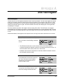
Drive Fault Register
202/1202
The bits in the Drive Fault register indicate the cause of a drive shutdown. The bits in this register are latched
until they are reset by setting the Fault Reset bit (bit 8) of the Drive Control register (100/1100, bit 8). After
turning the Fault Reset bit on, the drive may be re-started after turning the desired command bit in register
100/1100 off and then back on again. If the fault condition still exists, the identifying bit in this register will
immediately be set again.
The fault conditions reported in this register result in turning off the drive. The UDC task is not stopped
automatically if a drive fault occurs unless it is specifically instructed to do so in the application task. The user
must ensure that the AutoMax application task tests register 202/1202 and takes appropriate action if a fault
occurs.
Note that the status of this register is also reported in the error log for the task in which the error occurred.
Power Module Overtemperature Fault
The Power Module Overtemperature Fault
bit is set if either of the following conditions
occurs:
Bit 0
+H[ 9DOXH
+
6XJ 9DU 1DPH
)/7B27#
$FFHVV
5HDG RQO\
8'& (UURU &RGH
/('
30 )/7
• The PMI detects that motor current exceeds 100% of the Power Module’s
continuous capacity at maximum current for a pre-determined amount of time. At
maximum rated current, this trip will occur in 0.5 second.
• Hardware detects that the temperature of the Power Module’s heatsink exceeds
the configured maximum rating.
Instantaneous Overcurrent Fault
The Instantaneous Overcurrent Fault bit is
set if any of the three motor feedback
currents (Iu, Iv, Iw) exceeds 133% of
maximum RMS current.
Bit 1
+H[ 9DOXH
+
6XJ 9DU 1DPH
)/7B,2&#
$FFHVV
5HDG RQO\
8'& (UURU &RGH
/('
(;7 )/7
DC Bus Overvoltage Fault
The DC Bus Overvoltage Fault bit is set if
the DC bus voltage exceeds 400 VDC.
Drive Fault Register
Bit 2
+H[ 9DOXH
+
6XJ 9DU 1DPH
)/7B29#
$FFHVV
5HDG RQO\
8'& (UURU &RGH
/('
30 )/7
A-1
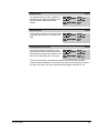
Vcc Power Supply Undervoltage Fault
The Vcc Power Supply Undervoltage Fault
bit is set if the input to the +5V supply on the
PMI drops below the necessary voltage to
maintain regulation.
Bit 3
+H[ 9DOXH
+
6XJ 9DU 1DPH
)/7B9&&#
$FFHVV
5HDG RQO\
8'& (UURU &RGH
/('
30 )/7
Position Error Fault
Bit 4
The Position Error Fault bit is set if the
position error exceeds the value set in the
PMI Tach Loss Maximum Position Error
register (register 166/1166).
+H[ 9DOXH
+
6XJ 9DU 1DPH
)/7B63'#
$FFHVV
5HDG RQO\
8'& (UURU &RGH
1$
/('
1$
Speed Error
Bit 5
The Speed Error Fault bit is set if the
maximum velocity error exceeds the value
set in the PMI Tach Loss Maximum Velocity
Error register (register 156/1156).
+H[ 9DOXH
+
6XJ 9DU 1DPH
)/7B63'#
$FFHVV
5HDG RQO\
8'& (UURU &RGH
1$
/('
1$
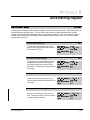
5HVROYHU %URNHQ :LUH )DXOW
%LW The Resolver Broken Wire Fault bit is set if a
sine or cosine signal from the resolver is
missing due to a broken wire or if the
resolver gain tunable (RES_GAN%) has
been set too low.
+H[ 9DOXH
+
6XJ 9DU 1DPH
)/7B7%:#
$FFHVV
5HDG RQO\
8'& (UURU &RGH
/('
)'%. 2.
Overspeed Fault
Bit 10
The Overspeed Fault bit is set if the motor’s
velocity exceeds the value entered as the
Overspeed Trip (RPM) configuration
parameter.
+H[ 9DOXH
+
6XJ 9DU 1DPH
)/7B263#
$FFHVV
5HDG RQO\
8'& (UURU &RGH
/('
(;7 )/7
PMI Power Supply Fault
Bit 12
The PMI Power Supply Fault bit is set if the
PMI power supply is not working correctly
A-2
+H[ 9DOXH
+
6XJ 9DU 1DPH
)/7B36#
$FFHVV
5HDG RQO\
8'& (UURU &RGH
/('
3:5 2.
SA500 Diagnostics, Troubleshooting, and Start-Up Guidelines
PMI Bus Fault
The PMI Bus Fault bit is set if a problem is
detected with the address and data bus on
the PMI regulator board in the Power
Module
Bit 13
+H[ 9DOXH
+
6XJ 9DU 1DPH
)/7B%86#
$FFHVV
5HDG RQO\
8'& (UURU &RGH
/('
1$
UDC Run Fault
The UDC Run Fault bit is set if the UDC task
stops while the minor loop is running in the
PMI.
Bit 14
+H[ 9DOXH
+
6XJ 9DU 1DPH
)/7B581#
$FFHVV
5HDG RQO\
8'& (UURU &RGH
/('
1$
Communication Lost Fault
The Communication Lost Fault bit is set if
the fiber-optic communication between the
PMI Processor and the UDC module is lost
due to two consecutive errors of any type.
Bit 15
+H[ 9DOXH
+
6XJ 9DU 1DPH
)/7B&20#
$FFHVV
5HDG RQO\
8'& (UURU &RGH
/('
&200 2.
This bit is set only after communication between the PMI Regulator and UDC
module has been established. This bit should be used in the run permissive logic for
the drive. Also refer to the CCLK Synchronized bit (register 200/1200, bit 14).
Drive Fault Register
A-3
A-4
SA500 Diagnostics, Troubleshooting, and Start-Up Guidelines
APPENDIX B
Drive Warning Register
'ULYH :DUQLQJ 5HJLVWHU
The warnings indicated by the Drive Warning register cause no action by themselves. Any resulting action is
determined by the application task. The user must ensure that the AutoMax application task monitors
register 203/1203 and takes appropriate action if any of these conditions occurs. If a warning condition is
detected, the corresponding bit is latched until the Warning Reset bit (bit 9) of the Drive Control register
(register 100/1100) is set.
Ground Current Warning
The Ground Current Warning bit is set if
ground current exceeds the value stored in
local tunable GIT_E1%.
Bit 0
+H[ 9DOXH
+
6XJ 9DU 1DPH
:51B*1'#
$FFHVV
5HDG RQO\
8'& (UURU &RGH
1$
/('
1$
Reference In Limit Warning
The Reference in Limit Warning bit is set if
the PMI torque reference value (register
102/1102) exceeds the maximum value
permitted (+/- 4095) and is being limited by
the system.
Bit 4
+H[ 9DOXH
+
6XJ 9DU 1DPH
:51B5,/#
$FFHVV
5HDG RQO\
8'& (UURU &RGH
1$
/('
1$
Tuning Aborted Warning
The Tuning Aborted Warning bit is set if any
of the automatic tuning procedures (e.g.,
resolver balance and gain calibration) is not
successful.
Bit 5
+H[ 9DOXH
+
6XJ 9DU 1DPH
:51B781#
$FFHVV
5HDG RQO\
8'& (UURU &RGH
1$
/('
1$
Volatile Gain Limit Warning
The Volatile Gain Limit bit is set if a speed or
position loop volatile gain value is out of
limit. This bit will only be set if the position
or speed loops are enabled.
Drive Warning Register
Bit 10
+H[ 9DOXH
+
6XJ 9DU 1DPH
:51B9*1#
$FFHVV
5HDG RQO\
8'& (UURU &RGH
1$
/('
1$
B-1
Rail Communication Warning
Bit 13
The Rail Communication Warning bit is set if
a rail communication problem is detected
and logged in registers 4, 10, 16, or 22.
+H[ 9DOXH
+
6XJ 9DU 1DPH
:51B5$/#
$FFHVV
5HDG RQO\
8'& (UURU &RGH
1$
/('
,2 )/7
CCLK Not Synchronized Warning
The CCLK Not Synchronized Warning bit is
set if the CCLK counters in the PMI
Regulator and the UDC module are
momentarily not synchronized.
Bit 14
+H[ 9DOXH
+
6XJ 9DU 1DPH
:51B&/.#
$FFHVV
5HDG RQO\
8'& (UURU &RGH
1$
/('
1$
PMI Communication Warning
Bit 15
The PMI Communication Warning bit is set if
a fiber-optic communication error is
detected between the PMI Processor
module and the UDC module.
+H[ 9DOXH
+
6XJ 9DU 1DPH
:51B&20#
$FFHVV
5HDG RQO\
8'& (UURU &RGH
1$
/('
1$
Communication errors in two consecutive messages will result in a drive fault.
B-2
SA500 Diagnostics, Troubleshooting, and Start-Up Guidelines
APPENDIX C
Interlock Register
,QWHUORFN 5HJLVWHU
Interlock tests are executed whenever bit 0 or 1 of register 100/1100 is set. The first problem detected will be
indicated by the identifying bit in this register. Note that these bits will prevent the vector or brushless minor
loop from running.
Configuration Parameters Not Loaded
The Configuration Parameters Not Loaded
bit is set if:
Bit 0
+H[ 9DOXH
+
6XJ 9DU 1DPH
,&B&1)#
$FFHVV
5HDG RQO\
8'& (UURU &RGH
1$
/('
1$
• the configuration parameters have not been downloaded into the UDC module
from the Programming Executive, or
• the alignment test has been enabled (register 100/1100, bit 1) when an induction
motor has been configured.
Gains Not Loaded
The Gains Not Loaded bit is set if the
required pre-defined local tunables are zero
or if a UDC task containing these tunables
has not been loaded to the PMI.
Bit 1
+H[ 9DOXH
+
6XJ 9DU 1DPH
,&B*$,1#
$FFHVV
5HDG RQO\
8'& (UURU &RGH
1$
/('
1$
RPI Missing
The RPI Missing bit is set if the Run
Permissive input on the Power Module is not
on.
Bit 2
+H[ 9DOXH
+
6XJ 9DU 1DPH
,&B53,#
$FFHVV
5HDG RQO\
8'& (UURU &RGH
1$
/('
1$
Faults Need Reset
The Faults Need Reset bit is set if previous
faults (register 202/1202) have not been
cleared.
Interlock Register
Bit 3
+H[ 9DOXH
+
6XJ 9DU 1DPH
,&B)/7#
$FFHVV
5HDG RQO\
8'& (UURU &RGH
1$
/('
1$
C-1
Rising Edge Required
Bit 4
The Rising Edge Required bit is set if a
rising edge is required on any command bit
in register 100/1100.
+H[ 9DOXH
+
6XJ 9DU 1DPH
,&B5,6(#
$FFHVV
5HDG RQO\
8'& (UURU &RGH
1$
/('
1$
This bit will be set if the application task has set the Fault Reset bit (register
100/1100, bit 8) but has not cleared and then re-set any command bits.
More Than One Request
Bit 5
The More Than One Request bit is set if
more than one operating mode is requested
at a time in register 100/1100 (bits 0 and 1).
+H[ 9DOXH
+
6XJ 9DU 1DPH
,&B025(#
$FFHVV
5HDG RQO\
8'& (UURU &RGH
1$
/('
1$
MCR Did Not Close
Bit 7
The MCR Did Not Close bit is set if the
optional output contactor did not close when
commanded to do so.
C-2
+H[ 9DOXH
+
6XJ 9DU 1DPH
,&B0&5#
$FFHVV
5HDG RQO\
8'& (UURU &RGH
1$
/('
1$
SA500 Diagnostics, Troubleshooting, and Start-Up Guidelines
APPENDIX D
Summary of UDC Module
Drive Fault Indicators
Status/Fault LEDs
CARD OK (green) - The CARD OK LED will turn on after the UDC module’s power-up
self tests have been successfully completed. The LED will remain on unless there is a
watchdog time-out or until power is cycled.
OS OK (green) - The OS (operating system) OK LED will turn on after the UDC
operating system is loaded into the module. It will remain on until power is cycled. On
subsequent power-ups, the LED will turn on to indicate that the OS is still resident in
the module. Note that this LED is also used to indicate any failure that may occur
during the power-up diagnostics. If the UDC module fails any of its power-up
diagnostics, the module must be replaced.
COMM A OK and COMM B OK (green) - The Communication Status LEDs will turn
on after the UDC module has established communication with the PMI rack(s) over
the fiber-optic link(s). COMM A indicates the status of communication link A. COMM
B indicates the status of communication link B. When an LED is lit, it indicates that
messages are being received over that channel. Each channel operates
independently of the other. If a channel is not being used, its LED will remain off. If
communication errors are detected in two consecutive messages, the COMM OK LED
will turn off and the DRV FLT LED will turn on. If the next message received by the
UDC module is correct, the COMM OK LED will turn back on. The Communication
Fault bit (register 202/1202, bit 15, FLT_COM@ ) will remain latched.
DRV FLT A and DRV FLT B (red) - The Drive Fault LEDs are normally off. If a Drive
Fault LED is lit, it indicates the a Drive Shutdown fault has been detected for the
indicated drive. When a drive fault is detected, a bit is set in register 202 for drive A or
register 1202 for drive B in the UDC module’s dual port memory. Bit 8 of the Drive
Status register (200/1200) is also set.
Summary of UDC Module Drive Fault Indicators
D-1
Drive Fault Error Codes
Drive faults are reported in the error log for the task in which the error occurred. The
drive fault error codes are defined below:
1008
Broken wire in resolver
1009
Not used
1010
Overspeed fault
1011
Not used
1012
PMI power supply fault
1013
PMI bus fault
1014
UDC run fault
1015
Fiber-optic link communication fault
1016
Power Module overtemperature fault
1017
Instantaneous overcurrent fault
1018
DC bus overvoltage fault
1019
Vcc power supply undervoltage
Error Codes
The UDC module can generate three error codes which will be displayed on the
leftmost AutoMax Processor:
Error 38 indicates that the UDC module has generated a Stop All. If this error occurs,
refer to the UDC task error log for additional information regarding the error.
Error 39 indicates a UDC module interrupt allocation has failed. In this case, try to
cycle power to the rack and reload the rack configuration and application tasks.
Error 3A indicates the UDC module’s operating system and the AutoMax operating
system are not compatible. If this error occurs, reload the most current operating
systems.
D-2
SA500 Diagnostics, Troubleshooting, and Start-Up Guidelines
APPENDIX E
Power Module LED Summary
The following table summarizes the LEDs on the SA500 Power Module. Refer to the
SA500 Power Modules instruction manual (S-3018) for more information regarding the
Power Module. Refer to the SA500 Drive Configuration and Programming instruction
manual (S-3044) for more information regarding the UDC module’s dual port registers.
Name
Description
LED
PWR OK
When lit, all power supply voltages for the PMI are at acceptable
operating levels.
Related Reg/Bit
202/1202 bit 12
FLT_PS@
PMI Power Supply Fault
LED
OK
When lit, indicates the PMI has passed its internal power-up
diagnostics and the on-board watchdog timer is being updated.
LED
COMM OK
When lit, indicates messages are being received correctly from the
UDC module over the fiber-optic link.
LED
P.M. FLT
When lit, indicates one of the following fault conditions has been
detected by the PMI:
Related Reg/Bit
202/1202 bit 2
FLT_OV@
DC Bus Overvoltage
Related Reg/Bit
202/1202 bit 3
FLT_VCC@
Vcc Power Supply Undervoltage
Related Reg/Bit
202/1202 bit 0
FLT_OT@
Power Module Overtemperature
LED
EXT FLT
When lit, indicates one of the following external fault conditions has
been detected by the PMI:
Related Reg/Bit
202/1202 bit 1
FLT_IOC@
Instantaneous Overcurrent
Related Reg/Bit
202/1202 bit 10
FLT_OSP@
Overspeed
Related Reg/Bit
101/1101 bit 2
EXT_LED@
User-programmed
LED
RAIL FLT
When lit, indicates communication between a rail and the PMI has
been disrupted, or that a rail is configured but is not plugged in.
Related Reg/Bit
203/1203 bit 13
WRN_RAL@
Rail Communication Warning
LED
FDBK OK
When lit, indicates that the PMI is receiving feedback from the
resolver and no resolver feedback faults have been detected.
Related Reg/Bit
202/1202 bit 8
FLT_TBW@
Resolver Feedback Broken Wire
Power Module LED Summary
E-1
Name
Description
LED
RPI
When lit, indicates the run permissive input signal has been
detected.
Related Reg/Bit
201/1201 bit 0
RPI@
RPI Input Status
LED
MCR
When lit, indicates that the MCR output signal is being driven on.
LED
AUX IN1
When lit, indicates the presence of a 115V signal on this input.
Related Reg/Bit
201/1201 bit 1
M_FDBK@
Aux Input 1/MFDBK Status
E-2
SA500 Diagnostics, Troubleshooting, and Start-Up Guidelines
APPENDIX F
Status of Data in the AutoMax Rack
After a STOP_ALL Command or
STOP_ALL Fault
AutoMax
Processor
PMI
Processor
UDC Module
LOCAL tunable variables
retained
retained
retained
LOCAL variables
retained
reset to 0
N/A
COMMON memory variables
non-volatile are retained;
others are reset to 0
N/A
N/A
I/O variables
(including UDC dual port memory)
inputs retained and
updated;
outputs are reset to 0
see below?
all I/O is reset to 0
Input values, including:
Feedback registers
UDC/PMI communication status
registers
UDC Error Log info
retained
retained
N/A
Output values, including:
Command registers
Application registers
ISCR registers
Scan-per-interrupt register
Scans-per-interrupt counter
reset to 0
reset to 0
N/A
Parameter configuration variables
N/A
retained
N/A
UDC test switch information
N/A
retained
N/A
D/A setup configuration
N/A
retained
N/A
Operating system
retained
retained
retained
Status of Data in the AutoMax Rack After a STOP_ALL Command or STOP_ALL Fault
F-1
F-2
SA500 Diagnostics, Troubleshooting, and Start-Up Guidelines
APPENDIX G
AutoMax Programming Executive
Access Levels
Rack Power Supply Keyswitch Position
Any
Position
PROTECT
SETUP
PROGRAM
User’s Access Level
Action
Force Common
None
Any
Level
Data
Task
Rack
Data
Task
Rack
No
No
No
No
No
Yes
Yes
Yes
Force Local
No
No
No
No
No
No
Yes
Yes
Force I/O
No
No
No
No
No
Yes
Yes
Yes
Set Common
No
No
No
No
No
Yes
Yes
Yes
Set Local
No
No
No
No
No
No
Yes
Yes
Set I/O
No
No
No
No
No
Yes
Yes
Yes
Set/Tune Tunable
No
No
No
Yes
Yes
No
Yes
Yes
Load Normal Config
No
No
No
No
No
No
No
Yes
Load Debug Config
No
No
No
No
No
No
No
Yes
Load Single POB File
No
No
No
No
No
No
Yes1
Yes
Load Single Task
No
No
No
No
No
No2
Yes
Yes
Delete Task
No
No
No
No
No
No
Yes
Yes
Start Task
No
No
No
No
No
No
Yes
Yes
Stop Non-Critical Task
No
No
No
No
No
No
Yes
Yes
Save Task from Rack
No
Yes3
No
Yes
Yes
No
Yes
Yes
Load All POB Files
No
No
No
No
No
Yes
Yes
Yes
Load All
No
No
No
No
No
No
No
Yes
Delete All Tasks
No
No
No
No
No
No
Yes4
Yes
Start All Tasks
No
No
No
No
No
No
Yes4
Yes
Stop All Tasks
No
No
No
No
No
No
Yes4
Yes
Load AutoMax OS
No
No
No
No
No
No
No
Yes
Load Single UDC OS
No
No
No
No
No
No
Yes1
Yes
Load All UDC OS
No
No
No
No
No
No
Yes1
Yes
Modify PC Task
No
No
No
No
No
No
Yes
Yes
Auto Run
No
No
No
No
No
Yes
Yes
Yes
Monitor
Yes
Yes
Yes
Yes
Yes
Yes
Yes
Yes
Note that a user with privileged (Data, Task, or Rack) access may relinquish this privilege by timing out after two minutes off-line, or by
selecting to relinquish access on-line. Functions not listed in the table do not require privileged access.
1. Must have Task access to both tasks in the UDC
2. A single task may be loaded with only Data access if the task does not already exist on the AutoMax Processor or UDC module.
3. Requires Task or Rack access.
4. Must have Task access to all tasks.
AutoMax Programming Executive Access Levels
G-1
G-2
SA500 Diagnostics, Troubleshooting, and Start-Up Guidelines
INDEX
A
Accessing the AutoMax rack, 4-1 to 4-2
Alignment test mode, 3-4
AutoMax programming executive
access levels, G-1
AutoMax rack
status of data, F-1
D
DC bus supply
POS and NEG terminals, 4-6
Definition of terms, 2-1
Diagnostics and troubleshooting, 2-1 to 2-6
Documentation, 1-1
Drive fault register, A-1 to A-3
Drive inspection and start-up guidelines, 4-4 to 4-16
checking installation with power off, 4-8 to 4-9
dynamic motor tests, 4-15
I/O verification, 4-10
physically inspecting the drive, 4-7
physically inspecting the motor, 4-8
recommended start-up sequence, 4-5
testing feedback registers and bits, 4-12 to 4-13
testing power modules with power on, 4-9
testing rail I/O registers, 4-11
testing UDC module meter ports, 4-14
UDC module test switch register, 4-13
UDC/PMI communication status, 4-10 to 4-11
uncoupled motor tests, 4-14 to 4-15
unexpected test results, 4-5 to 4-7
updating drawings and software listings, 4-16
Drive warning register, B-1 to B-2
Dynamic motor tests, 4-15
F
Faults, 2-4 to 2-5, A-1 to A-3
how the system reacts to drive faults, 2-4
Feedback registers and bits, 4-12 to 4-13
I
Idle mode, 3-1
Installation and start-up guidelines, 4-1 to 4-16
basic drive interconnections, 4-4
cabinet-enclosed wall-mounted drives, 4-3
floor-mounted drives, 4-3
installation requirements, 4-2
installing the drive, 4-3
installing the motor, 4-3
panel-mounted drives, 4-3
wiring the power module, 4-3
Interlock register, C-1 to C-2
Interlock tests, 2-3
Introduction, 1-1 to 1-2
L
LED summary, E-1 to E-2
M
MCR output control, 2-5
Meter ports
UDC module, 4-14
P
PMI operating modes, 3-1 to 3-4
overview, 2-2
PMI operating modes and diagnostics, 3-3
PMI run mode, 3-1 to 3-3
Power-up diagnostics, 2-3
R
Rail I/O registers, 4-11
Related Publications, 1-1
Run-time diagnostics, 2-3 to 2-6
T
Test equipment
recommended, 4-7
Typographical conventions, 1-2
I/O verification, 4-10
Index
Index-1
U
W
UDC module
drive fault indicators, D-1 to D-2
meterports, 4-14
UDC/PMI communication status register, 4-10
Updating drawings and software listings, 4-16
Warnings, 2-5 to 2-6, B-1 to B-2
clearing drive warnings, 2-6
Wiring the Power Module, 4-3
Index-2
SA500 Diagnostics, Troubleshooting, and Startup Guidelines
DIF
Documentation
Improvement Form
Use this form to give us your comments concerning this publication or to report an
error that you have found. For convenience, you may attach copies of the pages with
your comments. After you have completed this form, please return it to:
Rockwell Automation
RGA (Technical Publications)
25001 Tungsten Road
Cleveland, Ohio 44117
Fax: 216.266.7120
Publication Name:
Publication Number:
Publication Date:
Comments:
Your Name:
Date:
Company Name:
Phone: (
)
Address:
Thank you for your comments.
Technical Writing Internal Use
Date:
Follow-Up Action:
DIF Number:
Rockwell Automation / 24703 Euclid Avenue / Cleveland, Ohio 44117 / (216) 266-7000
Printed in U.S.A.
S-3022-1
August 1998