1
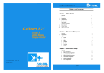
i SI3000 Broadband CPE Sinope568+ Wireless Home Gateway User Guide ii User Guide The Table of Contents contains “6” pages. The document contains “37” pages. Document ident. no.: “KSS60250B-EDE-030” Document Title: “Sinope568+ Wireless Home Gateway User Guide” © ISKRATEL 2008. All rights reserved. Technical specifications and features are binding insofar as they are specifically and expressly agreed upon in a written contract. Technical modifications possible. User Guide iii SAFETY PRECAUTIONS When using the equipment, observe the following signs, warnings and safety precautions. The following requirements should be fulfilled in order to ensure optimal performance of the device up-todate technology without any danger of damaging the equipment or the users: Sensitivity to static electricity: To protect the equipment sensitive to static electricity always use an antistatic wrist-strap. For an even higher level of protection, we recommend that you equip the room with antistatic floor, and wear an antistatic overall, cotton gloves and conducting footwear. Please read the installation instructions in the User Manual thoroughly before you set up the unit. Correct handling ensures the safety of the user and the equipment. The device is designed for indoor use. The unit should be used in a sheltered area, within a temperature range from +5 to +40 Celsius. Do not expose the unit to direct sunlight or other heat sources. The housing and electronic components may be damaged by direct sunlight or heat sources. Avoid using the device in dusty or damp places and places where there is a risk of explosion. Do not expose the device to humidity (in a bathroom for example). When the device is placed close to devices emitting electromagnetic interferences such as a microwave oven, HiFi equipment, etc., its performance is degraded. Move the device outside the disturbance range and the modem resumes its normal operation. Do not try to open or repair the unit yourself. The unit is a complicated electronic device that may be repaired only by authorized and qualified personnel. Only use the power adapter that comes with the package. Using a different voltage rating power adapter may damage this unit. Place this unit on a stable surface or mount it on the wall. Disconnect the power adapter before moving the unit. Do not put the cables where people can fall over them. Keep the package out of reach of children. When you would like to dispose of the unit, please follow the local regulations on conservation of the environment. User Guide iv CONTENTS Book C 1 Sinope568+ Wireless Home Gateway User Guide Introduction ............................................................................................................. 1 1.1 Features............................................................................................................................................ 1 1.2 Usage ................................................................................................................................................ 1 1.2.1 Internet access ........................................................................................................................... 1 1.2.2 Security....................................................................................................................................... 2 2 Getting started......................................................................................................... 2 2.1 3 Package contents ............................................................................................................................ 2 Installation of hardware.......................................................................................... 2 3.1 Ports ................................................................................................................................................. 2 3.2 Light indicators................................................................................................................................ 4 3.3 Support leg....................................................................................................................................... 6 3.4 Preliminary setup............................................................................................................................. 6 3.4.1 LAN and TCP/IP setup ............................................................................................................... 6 3.4.2 User defined IP address ............................................................................................................. 6 3.4.3 Obtain an IP automatically.......................................................................................................... 7 3.5 WEB management connection ....................................................................................................... 8 3.5.1 4 About the Web management...................................................................................................... 9 Managing Sinope568+ Router................................................................................ 9 4.1 Overview......................................................................................................................................... 10 4.2 Save Configuration........................................................................................................................ 10 4.3 Internet............................................................................................................................................ 11 4.3.1 4.4 To establish internet connection............................................................................................... 11 Local Network Configuration........................................................................................................ 12 4.4.1 IP Address ................................................................................................................................ 13 4.4.2 UPnP ........................................................................................................................................ 14 4.4.3 Global DHPC Settings .............................................................................................................. 14 4.4.4 DHPC Server Configuration ..................................................................................................... 15 4.4.4.1 To add a DHCP subnet ....................................................................................................... 16 4.4.4.2 To add a fixed host .............................................................................................................. 16 4.5 Wireless Network........................................................................................................................... 17 4.5.1 Wireless Global Settings .......................................................................................................... 18 4.5.2 To configure a wireless connection .......................................................................................... 18 4.5.2.1 64/128-bit encryption ........................................................................................................... 20 4.5.2.2 Wi-Fi Protected Access WPA/WPA2................................................................................... 22 4.6 Voice Configuration....................................................................................................................... 24 4.7 Security .......................................................................................................................................... 24 4.7.1 IP Filter ..................................................................................................................................... 25 4.7.1.1 IP Filter page ....................................................................................................................... 27 User Guide 4.7.1.2 v To add/edit a port filter rule or an IP validator rule .............................................................. 27 4.7.2 Parental Control/URL Filter ...................................................................................................... 29 4.7.3 DMZ Host ................................................................................................................................. 30 4.7.4 Port Forwarding ........................................................................................................................ 31 4.7.4.1 To add a port forwarding rule .............................................................................................. 32 4.8 DNS settings .................................................................................................................................. 33 4.8.1 LAN Host .................................................................................................................................. 33 4.8.2 Dynamic DNS ........................................................................................................................... 34 4.9 Port Configuration ......................................................................................................................... 34 4.9.1 To change the port function...................................................................................................... 35 4.10 Administration Password ............................................................................................................. 36 4.11 Remote Access .............................................................................................................................. 36 4.12 Status.............................................................................................................................................. 37 1 Introduction 1 1 Introduction 1.1 Features Sinope568+ wireless home gateway is a multi-mode ADSL and VoIP based wireless IAD (integrated access device) with the following features: high speed data transmission on single twisted copper pair full rate operations up to 24 Mbit/s in downstream compliant with ADSL, ADSL2, and ADSL2+: G.dmt (G.992.1), G.lite (G.992.2), G.dmt.bis (G.992.3), G.dmt.bis+ (G.992.5) and T1.413i2 over PSTN line four port 10/100BaseT Ethernet switch for LAN connection POTS (FXS) interfaces for telephone sets supporting VoIP (SIP, MGCP) automatic data detection (e.g. FAX) on POTS ports multiple voice codec support; VAD, CNG and caller ID support 802.11b/g WLAN - support for up to 54Mbit/s data transmission rate Wi-Fi WPA for data security accees for multiple Video clients VLAN tagging (802.1Q) (per port VLAN ID and Priority field assignment) and L2/L3 based QoS in upstream direction, SBT full featured Router and Firewall, support for secure wireless transmitting and authentication NAT (Network Address Translation) for single IP address Internet connection, used by the whole LAN community firewall filtering functions, allowing better network security and management WEB management and Telnet management over CLI (Command Line Interface) over Ethernet interface and remotely over ADSL interface support for centralized management node of multiple CPE (e.g. controlled mass remote SW upgrade and auto configuration provisioning via FTP), TR-069 compliant firmware upgrade over WEB management or TR-069 Universal Plug and Play feature (UpnP), Multi level WEB GUI Security: URL filtering, dynamic Firewall 1.2 1.2.1 Usage Internet access Your Sinope568+ can also be used for high speed Internet connections. The TCP/IP standards, most commonly used for using the Internet, are supported by the home gateway device. The PPPoE connections in dial-up or dial-in mode are also possible. In order to use your Sinope568+ for Internet access, there must be a DSLAM installed at a provider company's infrastructure near you. DSLAM is a rack of ADSL line cards that links many customer ADSL connections to a single high speed ine. A typical Internet access application is shown on figure below. You can also use NAT (Network Address Translation) services that your Sinope568+ provides when setting up an Internet connection. This feature allows multiple users on LAN to use the Internet connection, basing on one IP address. The DNS server and DNS relaying is also supported. 2 C. User Guide ethernet cable ATM DSL line internet DSLAM Figure 1-1: Example of Internet access connection 1.2.2 Security Connecting your computer to the Internet exposes it to a wide range of risks. The Sinope568+ wireless home gateway comes with security functions to safeguard your system and data. Three types of interfaces can be controlled by the Firewall: Internal (LAN), external (WAN) and DMZ (DeMilitarized Zone). A DMZ is usually used by a company that wants to host its own Internet services without sacrificing unauthorized access to its private network. Typically, the DMZ contains devices accessible to Internet traffic such as HTTP, FTP, DNS and SMTP servers. You can configure the Firewall to allow or block access from one interface type to another interface type. You can configure the Firewall by using a default Security level, by Firewall port filters, by Firewall validators and by Security triggers. 2 2.1 Getting started Package contents The package comes with the following items: Sinope568+ ADSL Modem unit AC adapter Ethernet RJ-45 UTP cord Phone RJ-11 cord Support leg CD-ROM containing user's guide 3 3.1 Installation of hardware Ports The following figure shows the rear panel of your Sinope568+ home gateway. 3.1 Ports 3 Figure 3-1: The rear panel of the Sinope568+ home gateway. There are several data and voice connectors and an AC power socket on the rear panel of the modem. ON/OFF Switch for turning the device on or off. POWER Plug the power cable to ensure power to the Sinope568+ home gateway. RES (Reset button) This button is used to reset the configuration of the home gateway to factory default values. You must hold this button while the home gateway is starting-up until ALM led will start flashing fast (about 30 seconds). Sinope568+ will use factory default settings only for the time it is running. If you want to preserve factory default settings save the configuration. ETH1, 2, 3, 4 4 Ethernet 10Base-T/100Base-T ports Use a straight-through or crossover Ethernet cable to connect your Sinope568+ home gateway to a computer or any other device. Up to four devices can be connected without using external Ethernet switch. It is possible to manage the settings of the home gateway with telnet connection using this port. The factory setting for IP address is 192.168.1.1. WAN This port is used for connecting the ADSL cable to your phone jack. Connect the Sinope568+ home gateway to the WAN port to access the Internet. TEL1/TEL2 This port is used to connect analog phones. 4 C. User Guide 3.2 Light indicators The following figure shows the front panel of your Sinope568+ home gateway. Figure 3-2: The front panel of the Sinope568+ home gateway There are five LEDs on the front panel of the modem that indicate the status of your Sinope568+ home gateway: Power Broadband Data Wireless Phone 3.2 Light indicators Table 3-1: Light indicators LED Power Broadband Data Wireless Phone 5 Status Description off Power is off. on (30%) Power is on but there is no device activity. on (70%) Broadband line is established. blinking slow The device is trying to detect the broadband carrier signal. blinking fast The broadband carrier is detected and the device is trying to train. off No IP connection. on (70%) IP session is established, no WAN traffic. flickering IP session is established, WAN traffic activity. blinking slow IP connection failed. off No devices connected to the home gateway, or the devices are turned off. on (70%) Devices are connected to the home gateway and turned on. flickering Data transfer activity. off Wireless access point is disabled. on (70%) Wireless access point is enabled. flickering Wireless connection is in use. off Phone service is disabled. on (70%) Phone service is enabled. blinking Phone service is in use. 6 3.3 C. User Guide Support leg Insert the modem into the support leg provided (see figure below), then place the unit on a flat even surface. Figure 3-3: Support leg installation 3.4 Preliminary setup 3.4.1 LAN and TCP/IP setup This section of the manual provides important information to keep in mind when setting up the first connection between your computer and Sinope568+ home gateway. The factory default settings of the Sinope568+ home gateway have values listed bellow: Table 3-2: Factory default settings Local IP address 192.168.1.1 Subnet mask 255.255.255.0 DHCP server Disabled 3.4.2 User defined IP address The default option is to set up the connection by yourself. In this case you must specify the IP address of your system. Be careful that the subnet values of your system and the modem are the same, e.g. 192.168.1.0 (IP address 192.168.1.1 for modem and IP address 192.168.1.2 for computer). Example is shown on the picture bellow. 3.4.3 Obtain an IP automatically 7 Figure 3-4: User defined IP address set up for Local Area Connection on computer The IP address of the modem can also be changed, you can learn about that under the WEB management connection sections of the manual. 3.4.3 Obtain an IP automatically If you enable DHCP server in Sinope568+, is the easiest way to set up a connection to configure the LAN adapter on your system to obtain an IP automatically. This can be done in your operational system by managing the Local Area Connection Properties. The TCP/IP protocol must be installed on your system and set to obtain an IP address automatically. Example is shown on the picture below. 8 C. User Guide Figure 3-5: IP obtain automatically set up for Local Area Connection on computer 3.5 WEB management connection Sinope568+ home gateway has embedded WEB server included in the firmware. This section of the document describes the basic principles on how to manage the settings of the Sinope568+ home gateway using WEB management connection with any web browser. 1. To access Web management connection enter the URL in your web browser http://<ipaddress>, for example http://192.168.1.1. <ipaddress> is the Local IP address of the Sinope568+ home gateway, e.g. 192.168.1.1 for factory default settings. The IP addresses of modem and computer must be parts of the same IP network (e.g. 192.168.1.0). The following dialog box opens. Figure 3-6: Web connection 2. Enter the user name user and password user. 3.5.1 About the Web management 9 3. Click OK to continue. The following page opens. Figure 3-7: Overview page 3.5.1 About the Web management The Web management interface enables you to view your modem settings, edit and configure them. The interface is divided into two frames: left frame - navigation tree The navigation tree is intended for navigating and accessing the modem configuration pages. The elements listed in the tree are hyperlinks. When you click a link, a corresponding configuration page will be displayed in the right frame. right frame - display area Displays a configuration page for the selected element. 4 Managing Sinope568+ Router This section describes the web management interface, configuration options and gives instructions for configuring your router. The main areas of configuration are divided into the following groups and elements: Device “Overview” Configuration “Save Configuration” “Internet” “Local Network Configuration” “Wireless Network” “Voice Configuration” “Security” “DNS settings” “Port Configuration” 10 C. User Guide System “Administration Password” “Remote Access” Status Internet Connection Wireless Connection Traffic Statistics DHCP Table ARP Table 4.1 Overview The Overview page displays useful current information about Sinope568+. The page shows the network addresses being used by Sinope568+ to connect to your PCs, and for your Internet connection, as well as the version information for Sinope568+.The hardware version information is set by Iskratel so the make and model of your device can be quickly identified in the unlikely even that you need assistance. Figure 4-1: Device Overview 4.2 Save Configuration This page allows you to save the current configuration changes you have made to the flash memory of the device. 1. Select Configuration > Save Configuration. The following page opens. 4.3 Internet 11 Figure 4-2: Save Configuration page 2. To save the changes you have made, click Commit. 4.3 Internet You can access the Internet in one of several ways depending on the service provided by your Internet Service Provider (ISP): Automatically detect settings. With this access type, Sinope568+ will scan for a link to the Internet. Using PPPoA (Point to Point Protocol over ATM) allows Internet access only after you have entered a valid username and password. Using PPPoE (Point to Point Protocol over Ethernet) allows Internet access only after you have entered a valid username and password. Using DHCP (Dynamic Host Control Protocol) automatically allows Internet access. Use direct manual settings provided to you by your ISP. i 4.3.1 Note: Some providers do not support all connection types listed above. In this case only available types are displayed! To establish internet connection 1. Select Configuration > Internet. The following page opens. 12 C. User Guide Figure 4-3: Internet connection configuration page 2. Click Connect. The Log In page opens. Figure 4-4: Log In page 3. Type the username and password provided by your ISP. To continue, click Connect. 4.4 Local Network Configuration These pages allow you to configure the following settings: “IP Address” “UPnP” “Global DHPC Settings” “DHPC Server Configuration” To access these settings: 1. Select Configuration > Local Network. The Local Network Configuration page opens. 4.4.1 IP Address 13 Figure 4-5: Local Network Configuration page 2. The settings are accessible through tabs listed below the page title. To access a specific setting, click the corresponding tab. 4.4.1 IP Address The IP address page displays the IP address and subnet mask for Sinope568+. These provide a unique address for Sinope568+, as well as giving it the range of addresses to use for other PCs that are connected to Sinope568+. Sinope568+'s default IP address and subnet mask are suitable for most networks. 1. In the Local Network Configuration page, click the IP Address tab. The following page opens. Figure 4-6: IP Address page 2. If you change any of the settings, confirm and save the settings by clicking Apply. 14 4.4.2 C. User Guide UPnP Universal Plug and Play (UPnP) is an architecture for pervasive peer-to-peer network connectivity of intelligent appliances, wireless devices, and PCs of all form factors. It is designed to bring easy-to-use, flexible, standards-based connectivity to ad-hoc or unmanaged networks whether in the home, in a small business, public spaces, or attached to the Internet. Universal Plug and Play is a distributed, open networking architecture that leverages TCP/IP and the Web technologies to enable seamless proximity networking in addition to control and data transfer among networked devices in the home, office, and public spaces. 1. In the Local Network Configuration page, click the UPnP tab. The following page opens. Figure 4-7: UPnP Settings 2. Click Enable UPnP to help support applications that would not otherwise work behind a Router. 3. To continue, click Apply. 4.4.3 Global DHPC Settings The Global DHCP Settings page allows you to enable or disable DHCP Server running on your Sinope568+. DHCP Server can automatically configure your PCs connected to Sinope568+ to be able to connect to the Internet. You must enable DHCP Client (Automatically configure IP address) on your computer. 1. In the Local Network Configuration page, click the Global DHCP Settings tab. The following page opens. 4.4.4 DHPC Server Configuration 15 Figure 4-8: Global DHCP Settings 2. Enable or disable the DHCP server. By default, the DHCP server is enabled. 3. Click Apply. 4.4.4 DHPC Server Configuration The DHCP Server Configuration page allows you to create DHCP server subnets and DHCP server fixed host IP/MAC mappings. In the Local Network Configuration page, click the DHCP Server Settings tab. The page displays any configured DHCP server subnets or DHCP fixed IP/MAC mappings. Figure 4-9: DHCP Server Configuration page 16 4.4.4.1 C. User Guide To add a DHCP subnet 1. On the DHCP Server Settings page, click Add Subnet. The following page is displayed. Figure 4-10: Add DHCP server subnet 2. Type in: • value and netmask of the subnet and set the maximum and default lease times, • DHCP address range or use a default range, • set your Synope568+ to give out its own IP address as the DNS Server address, • set your Synope568+ to give out its own IP address as the default Gateway address. 3. Click Apply. 4.4.4.2 To add a fixed host 1. In the DHCP Server Settings page, click Add Fixed Host. The following page is displayed: 4.5 Wireless Network 17 Figure 4-11: Add Fixed Host page 2. Type in: IP address that will be given to the host with the specified MAC address, MAC address, maximum lease time (default is 86400 seconds). 3. Click Apply. 4.5 Wireless Network Sinope568+ allows you to connect wireless PCs to the Internet. The Wireless Network pages let you enable and disable this feature and set various security settings for your wireless network. These pages allow you: To Set “Wireless Global Settings” “To configure a wireless connection” To access these settings: Select Configuration > Wireless Network. The Wireless Network page opens. Figure 4-12: Wireless Network page 18 4.5.1 C. User Guide Wireless Global Settings 1. Select Configuration > Wireless Network. Click the Global settings tab. The following page is displayed. Figure 4-13: Global Settings page 2. To make sure Sinope568+ does not transmit on illegal frequencies, you must set where you are in the world. In the Country Setting area, select your country from a drop-down list. 3. In the Profiles area, select the type of wireless network you wish to use. 4. In the Channel Selection select one of the following: • Allow Sinope568 to select channel - the device will automatically select the best channel • Select a channel manually - select a channel yourself. 5. Click Confirm. 4.5.2 To configure a wireless connection By default, wireless connection is disabled. To configure it, you must first enable wireless networking. 1. Select Configuration > Wireless Network. The following page opens. 4.5.2 To configure a wireless connection Figure 4-14: Wireless Port settings The preconfigured wireless network settings wireless and wireless1. You must first enable 2. Enable the connection wireless. Click the Edit link. The following page opens. Figure 4-15: Enable/Disable Wireless network 3. Select the option Enabled and click Next. The following page opens. Figure 4-16: Wireless Network Name 4. Provide a unique network name. Type the name in the Network Name (SSID) field. 5. Click Next. The following page opens. 19 20 C. User Guide Figure 4-17: Wireless Network Encryption 6. Select encryption for wireless network data transfer. Select one of the following: - Off - no encryption on the wireless network - 64-bit encryption on the wireless network. A basic encryption method. You must provide a 10-character hex key. - 128-bit encryption on the wireless network. Advanced encryption method. You must provide a 26-character hex key. - Wi-Fi Protected Access (WPA) on the wireless network. A reliable security method. You must provide a password of 8 to 63 characters long. - Wi-Fi Protected Access2 (WPA2) on the wireless network Depending on the encryption method you have selected, follow one of the following instructions: “64/128bit encryption” or “Wi-Fi Protected Access WPA/WPA2”. 4.5.2.1 64/128-bit encryption For both encryption methods, you need to configure a key. Your wireless network can be accessed only by providing this key. 1. Select 64-bit encryption on the wireless network (or 128-bit encryption on the wireless network). Figure 4-18: 64/a28-bit encryption 2. Click Next. The following page opens. 4.5.2.1 64/128-bit encryption 21 Figure 4-19: Key or password selection 3. Select on of the two options: • Key Enter a key of your choice. For a 64-bit encryption, the key must consist of 10 characters long, (letters A to F or digits 0 to 9). For a 128-bit encryption, the key must be 26 characters long (letters A to F or digits 0 to 9). • Pasphrase Select this option if you want the device to generate a key based on the passphrase that you provide. 4. After you have provided the key, the following page opens. Figure 4-20: Address Authentication 5. In this page select one of the following options: • Allow any wireless PCs to connect - with this option you allow any PC to connect to your wireless network. • Allow all wireless PCs to connect except those I specify - with this option you specify those PCs that will be denied access to your wireless network. • Only allow the wireless PCs I specify to connect - with this option, you specify a list of PCs that are allowed to connect to your wireless network. 6. If you have selected to specify a deny or allow list of PCs in the previous step, you will be prompted to add addresses of PCs to the list. 7. Before you confirm changes that you have made, the following page is displayed. 22 C. User Guide Figure 4-21: Wireless Network - Confirm settings 4.5.2.2 Wi-Fi Protected Access WPA/WPA2 For both encryption methods, you need to set a passphrase. Your wireless network can be accessed only by providing this passphrase. 1. Select Wi-Fi Protected Access (WPA) on the wireless network (or Wi-Fi Protected Access2 (WPA2) on the wireless network). The following page opens. Figure 4-22: Wi-Fi Methods 2. Select the Authentication method and the Encryption protocol method. 3. Click Next. The following page opens. 4.5.2.2 Wi-Fi Protected Access WPA/WPA2 23 Figure 4-23: Wi-Fi Protected Access 4. Provide a passphrase to access your wireless network. The passphrase must consist of at least 8 and not more than 63 characters. Figure 4-24: Address Authentication 5. After you have provided the passphrase, the following page opens. Figure 4-25: Address Authentication 6. In this page select one of the following options: • Allow any wireless PCs to connect - with this option you allow any PC to connect to your wireless network. • Allow all wireless PCs to connect except those I specify - with this option you specify those PCs that will be denied access to your wireless network. • Only allow the wireless PCs I specify to connect - with this option, you specify a list of PCs that 24 C. User Guide are allowed to connect to your wireless network. 7. If you have selected on of the last two options in the previous step, you will be prompted to add the MAC addresses of PCs to the list. 8. Before you confirm changes that you have made, the following page is displayed. Figure 4-26: Wireless Network - Confirm settings 4.6 Voice Configuration The Voice Configuration page enables you to monitor the status of voice connections on your home gateway device. Click the Voice option. The following page is displayed. Figure 4-27: Voice Settings page You can have two phones connected to your device. The status of each is indicated either by Phone 1 (connected to port TEL1) or Phone 2 (connected to port TEL2). Status: displays the status of your phones (registered, unknown,...). Number: displays the directory number of your phone. 4.7 Security Sinope568+ contains advanced security features that prevent other computers on the Internet from connecting to your PCs. You should only change the default security settings if you have experience in network configuration. In most cases you will not need to make any changes. 4.7.1 IP Filter 25 The following security features can be configured: “Port Forwarding” “Parental Control/URL Filter” “DMZ Host” “IP Filter” To access these pages: 1. Select Configuration > Security. The following page opens. Figure 4-28: Security setting page 2. To access and configure specific security feature, click the corresponding tab in this page. 4.7.1 IP Filter Stateful Firewall Settings on this page are actually Firewall settings. A stateful Firewall tracks the movement of packets over a period of time. If an outgoing packet includes a request for responses from certain types of incoming packet, the packet is tracked to ensure that only those types of incoming packets are allowed through the Firewall. Other types of traffic are blocked. Each time outbound packets are sent from an inside host to an outside host, the following stateful information is logged by the Firewall: source and destination addresses port details; protocol type and range of source and destination ports sequencing information additional flags for each connection associated with that particular inside host All inbound packets are compared against this logged information and any manually configured address and port details. These packets are only allowed through the Firewall if an appropriate connection exists or if a filter explicitly allows that traffic. Address and port details are configured by defining Firewall validators and filters. This makes it very difficult for hackers to break through the stateful Firewall, because they would need to know addresses, port numbers, sequencing information and individual connection flags for an inside host. Firewall policies A Firewall policy is the name of the rule that applies to a data path between two classes of security interface. You can add different address validator and filter rules to each policy in order to provide different levels of security to the inside networks attached to the router. For example, if your DMZ (DeMilitarited Zone) contains an FTP server that can be accessed by external hosts, the rules between the dmz and external security interfaces will be less stringent than those between the internal and external security interfaces. Policies exist by default: between the external interface and the internal interface between the external interface and the DMZ interface between the DMZ interface and the internal interface 26 C. User Guide Policies are set to block only the IP addresses specified in validator rules. If you have configured your router and created security interfaces, the data paths between each of the router’s security interfaces look like this: dmz-external dmz interface (ipdmz) in t er n Firewall al- ex te r na l z dm - in te l r na external interface (ipwan) internal interface (iplan) Figure 4-29: Firewall policies between security interfaces You can use the default, pre-configured Firewall policies, add new policies, and delete policies. Port Filters A Port Filter is a rule that determines how the Firewall should handle packets being transported on a policy between two security interfaces. You can create separate filter rules based on: the protocol type of the traffic allowed to be transported which TCP/UDP port numbers the packets are allowed to be transported on the name of the well-known protocol, service or application allowed to be transported source and destination addresses Whichever type of filter rule you use, you must also determine which direction packets should be allowed to travel in: inbound; permitted traffic is transported from the outside interface to the inside interface outbound; permitted traffic is transported from the inside interface to the outside interface both; inbound and outbound rules apply i Note: If you create a filter and you want to change the direction that packets are allowed to travel in, you must delete the original filter and create another. IP Validators An IP Validator is a rule that determines how the Firewall should handle packets received from or sent to a specific IP address or a range of addresses. If you know the address details of a specific external host whom you believe may attempt to infiltrate or damage your internal network, you can block traffic from that host. Similarly, if an internal host is accessing an external web site that contains unacceptable material, you can block their access to it. You must also determine which direction packets should be allowed to travel in: inbound; permitted traffic is transported from the outside interface to the inside interface outbound; permitted traffic is transported from the inside interface to the outside interface both; inbound and outbound rules apply 4.7.1.1 IP Filter page 4.7.1.1 ! 27 IP Filter page Warning: These are advanced settings and you should not change them unless you completely understand how things work. 1. Select the IP Filter tab. The following page opens. Figure 4-30: IP Filter Settings 2. You can select Disable or Enable to disable or enable IP Filtering (Firewall). 3. If there are any rules already configured, you can edit or delete them in this page. Select Edit or Delete option accordingly. all-out ext-int and all-out ext-dmz port filter rules are configured by default and should not be deleted. If all-out ext-int port filter rule is deleted, internet connection will not work and you will have to create a new default ext-int policy port filter rule. 4. To add a new Port Filter Rule or IP Validator Rule, click Add. 4.7.1.2 To add/edit a port filter rule or an IP validator rule 1. In the IP Filter Settings, click the Add button to add, or the Edit icon to edit the rule. The following page opens: 28 C. User Guide Figure 4-31: Add IP Filtering Rule 2. Type in Filter Rule Name. 3. Select policy: • ext-int • ext-dmz • dmz-int 4. Select the direction to filter packets: • Outbound traffic • Inbound traffic • Both 5. Select Port Filter Rule or IP Validator Rule. 6. Port Filter Rule: Protocol: • ALL (Used for default Port Filter rule) • TCP • UDP • ICMP • GRE Filter Action: • Allow (Allow specified packets in firewall) • Deny (Deny specified packets in firewall) Source IP Range: 4.7.2 Parental Control/URL Filter 29 • Start • End Destination IP Range: • Start • End Source Port Range: • Start • End Destination Port Range: • Start • End Status: • Enable (Enable Port Filter Rule) • Disable (Disable Port Filter Rule) 7. IP Validator Rule: IP address: • SINGLE (IP Validator Rule blocks single IP address) • SUBNET (IP Validator Rule blocks (subnet) group of IP addresses) IP address Netmask Status: • Enable (Enable IP Validator Rule) • Disable (Disable IP Validator Rule) 8. To confirm the settings, click Apply. 4.7.2 Parental Control/URL Filter Parental Control feature provides the facility to block WAN side access from the specified internal PCs in your network for a specified duration as configured by the user (Parent or administrator). Many parents want to exercise some control over the Internet access from their child PCs. The Parental Control feature will enable a new time based controlling feature. It will give the control to the parents/ administrators to control the traffic from different internal PCs connected to router. 1. Select the Parental Control/URL Filter tab. The following page opens. 30 C. User Guide Figure 4-32: Parental Control/URL Filter 2. Set the rule action: • Choose Allow to allow access only to URLs that you specify • Choose Deny to deny access to URLs that you specify. 3. Click Apply to confirm Rule Action. 4. Set the rule. Fill in the following fields: • Filter Name: enter the name of the URL filter (alphanumeric characters). • Policy Name (firewall policy):ext-int, ext-dmz, dmz-int • Domain Filter: Any alphanumeric string that represents a valid domain name. You can use wildcard characters * and ? to specify the filter. • Start Time: specify the start time of this filter to become active. • End Time: specify the end time after which this filter will no longer be active. Note: For correct time of day settings, SNTP client must be configured. i 5. Click Apply. i 4.7.3 Note: After you have set the URL filter and before it becomes active, you should wait for a couple of minutes before browsing the internet. The time is required to clear the DNS cache and to block the DNS requests. DMZ Host A DMZ host is a computer on your local network that can be accessed from the Internet regardless of port forwarding and firewall settings. i Note: The Port forwarding rules will override these DMZ settings. 1. Select the DMZ Host tab. The following page opens. 4.7.4 Port Forwarding 31 Figure 4-33: DMZ Host 2. Click Edit. The following page opens. Figure 4-34: DMZ Host Configuration 3. To set up a DMZ host: • Select Forwarded to the DMZ host • In the IP Address of DMZ host filed, type in its IP address. 4. Click Apply. 4.7.4 Port Forwarding You can create port forwarding rules to allow certain applications to work on your computers if the Internet connection uses NAT. NAT allows you to connect multiple computers to the Internet (or any other IP network) using one IP address. 1. Select the Port Forwarding tab. The following page opens. 32 C. User Guide Figure 4-35: Port Forwarding 2. The page displays any previously created rules. You can edit or delete these rules, or add new rules. 4.7.4.1 To add a port forwarding rule 1. In the Port Forwarding page, click Add. The following page is displayed: Figure 4-36: Add New Port Forwarding Rule 2. In the Name area, choose predefined applications (Predefined) or your applications defined by yourself (User defined). • Pre-defined: Select one of the predefined groups of applications and then the application. • User defined: Type the name of your application. 3. In the WAN Interface field, select the WAN interface on which you want to apply the port forwarding rule: • Forward to Internal Host Name: Select the internal host name of device to which you want to forward packets. • Forward to Internal Host IP Address: Type the internal host IP address of device to which you want forward packets. 4.8 DNS settings 33 4. By using the rules: If you choose predefined applications, the data in these fields are set from applications base. If you choose user defined application, you must enter data manually. • Protocol: Select protocol which is used by your application. Each application has defined protocols and ports that it uses. Data can be found on the Internet for example. Also, more than one protocol could be set for one application. • External Port (Port Start, Port End): Type External Port (Start, End) of your application (range 165535). Start and End values could be equal. Also, external and internal ports could be equal. • Internal Port (Port Start, Port End): Type Internal Port (Start, End) of your application (range 165535). Start and End values could be equal. Also, external and internal ports could be equal. 5. Click Apply to confirm the settings. 4.8 4.8.1 DNS settings LAN Host 1. Select Configuration > DNS. The following page opens. Figure 4-37: DNS Table - add new LAN host 2. To add a new LAN host to the DNS table, click the Create a new DNS hostname entry manually. The following page opens. Figure 4-38: Add hostname entry 3. Enter the name of the host in the Host Name field and the IP address in the IP Address field. 4. Click Apply. 34 C. User Guide 4.8.2 Dynamic DNS Dynamic DNS allows computers on the Internet to access hosts on your network using a domain name rather than an IP address. This feature is very useful if you have been assigned a dynamic IP address form your ISP. Dynamic DNS provides a permanent domain name for your PC even when your IP address has changed. In order to use this feature, you must subscribe to a dynamic DNS service. Currently supported are. dydns.org, or tzo.com. 1. Select Configuration > DNS. The following page opens. Figure 4-39: Dynamic DNS 2. To enable Dynamic DNS feature: • Select Enabled. • From a drop down list select the corresponding DNS Provider that you have previously subscribed to. • Select the type of the internet connection. • In the User Name field, type your DNS subscription username. • In the Password field, type the corresponding password. • In the Domain Name field, type the domain you have registered at the this DNS provider. 3. Click Apply. 4.9 Port Configuration The Port Configuration page allows you to change the way local ports of Sinope568+ are used. The default port configuration is as follows: Ethernet1-2: ports for connecting PCs or other network devices (data) Ethernet3-4: ports for connecting Set Top Boxes (video) USB1-2: ports for wireless data or voice transmission 4.9.1 To change the port function 35 To view the current port configuration settings, click the Port Configuration option. The following page opens. Figure 4-40: Port Configuration 4.9.1 To change the port function Depending on device type connected to the port, you can change the port function. 1. To change the port function, click Change... . The following page opens. Figure 4-41: Port Configuration - Setup 2. Select one of the available options: data - computer connected to this port video - Set Top Box connected to this port voice - VoIP phone connected to this port nothing - select this if you do not want to use this port 3. Click Next to continue. The following page opens. 36 C. User Guide Figure 4-42: Port Configuration - Confirm 4. Examine the settings and if appropriate, click Confirm Changes. 4.10 Administration Password 1. To change the administration password, select System > Admin Password. The following page opens Figure 4-43: Administration Password 2. Type in the new password twice - in the New password field and in the Confirm new password field. The password can be any combination of letters and numbers of up to 20 characters. 3. To confirm new settings, click Apply. 4.11 Remote Access Management Stations allow a specific host (or range of hosts) remote access to your home gateway device without having to go through NAT and/or Firewall. This function is intended for expert users (helpdesk, your ISP administrators,...) in order to connect to your device and configure it remotely. To configure remote access: 1. Select System > Remote Access. The following page opens. 4.12 Status 37 Figure 4-44: Remote Access 2. Select the Web Browser option. 3. In the fields Start IP Address and End IP Address, type the host IP address or address range. 4. If necessary, change the port number (Web Server Port on Wan Interface field) - the default port is port 80. 5. Click Apply. 4.12 Status The status pages allow you to observe the following: Internet Connection Wireless Connection (list of connected wireless PCs) Traffic Statistics DHCP Table ARP Table Select a corresponding link to observe these statuses.