1
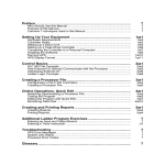
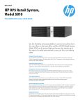
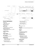
Allen-Bradley SLC 500t Family of Programmable Controllers Addressing Reference Manual Important User Information Because of the variety of uses for the products described in this publication, those responsible for the application and use of this control equipment must satisfy themselves that all necessary steps have been taken to assure that each application and use meets all performance and safety requirements, including any applicable laws, regulations, codes and standards. The illustrations, charts, sample programs and layout examples shown in this guide are intended solely for purposes of example. Since there are many variables and requirements associated with any particular installation, Allen-Bradley does not not assume responsibility or liability (to include intellectual property liability) for actual use based upon the examples shown in this publication. Allen-Bradley publication SGI–1.1, Safety Guidelines for the Application, Installation, and Maintenance of Solid-State Control (available from your local Allen-Bradley office), describes some important differences between solid-state equipment and electromechanical devices that should be taken into consideration when applying products such as those described in this publication. Reproduction of the contents of this copyrighted publication, in whole or in part, without written permission of Allen-Bradley company, Inc., is prohibited. Throughout this manual we use notes to make you aware of safety considerations. ATTENTION: Identifies information about practices or circumstances that can lead to personal injury or death, property damage or economic loss. Attention statements help you to: identify a hazard avoid the hazard recognize the consequences Important: Identifies information that is critical for successful application and understanding of the product. 2 Data Table Addressing for the SLC 500t Family of Processors Introduction This addressing reference helps you specify data table addresses in SLC 500t fixed and modular programmable controllers. It contains information for the following processors: all SLC 500 Fixed Programmable Controllers The following SLC 500 Modular Programmable Controllers - SLC 5/01 CPU - SLC 5/02 CPU - SLC 5/03 CPU Locating Addressing Information For information about See page memory maps 3 general format for direct logical ASCII addressing 4 logical addressing for I/O image elements 5 logical addressing for the status elements 7 logical addressing for integer elements 9 logical addressing for binary elements 11 logical addressing for floating-point elements 13 logical addressing for timer structures 14 logical addressing for counter structures 16 logical addressing for control block structures 18 1 SLC 500 Family of Programmable Controllers Addressing Reference For specific information about the content of data table files, consult the: PLC programmer, who assigns data to specific memory locations SLC 500 Fixed Hardware Style Installation and Operation Manual, publication 1747–NI001. SLC 500 Modular Hardware Style Installation and Operation Manual, publication 1747–NI002. Advanced Programming Software (APS) User’s Manual, publication 1747–NM002. Important: Throughout this publication we use $ as the logical address identifier. This is an entry for INTERCHANGE software. It is also an entry for 6200 programming software in sending a message from other stations to a SLC 500 processing station. It is not used in 6200 programming software for internal addressing. 2 SLC 500 Family of Programmable Controllers Addressing Reference Memory Map Table A shows the logical arrangement of the data table for SLC 500 processors. Table A Data Table Memory Map File Number File Type 0 OUTPUT IMAGE 1 INPUT IMAGE 2 STATUS 3 BINARY 4 TIMER 5 COUNTER 6 CONTROL 7 INTEGER 8 FLOATING–POINT 9 NETWORK Logical Address $O:0 to $O:30 $I:0 to $I:30 $S:0 to $S:n $B3:0 to $B3:255 $T4:0 to $T4:255 $C5:0 to $C5:255 $R6:0 to $R6:255 $N7:0 to $N7:255 $F8:0 to $F8:255 $x9:0 to $x9:255 $x10:0 to $x255:255 Comments See Note 1 See Note 2 See Note 3 10 See Note 4 thru USER DEFINED 255 Notes 1 Address range is processor specific; see Logical Addressing for the Status Elements section. 2 Only the SLC 5/03 series B processor supports floating-point data type. Do not use this area for processors that do not support floating-point data. 3 If non SLC 500 devices exist on the DH-485 link, use this area for network transfer. You can use either binary (B) or integer (N) file types by specifying the appropriate letter for x. Otherwise, you can use file 9 for user-defined files. 4 Use this area when you need more binary, timer, counter, control, integer, floating-point, or network files that will fit in the reserved files. You can use binary (B), timer (T), counter (C), control (R), integer (N), floating-point (F), or transfers (B and/or N) file types by specifying the appropriate letter for x. You cannot use this area for output image, input image, and/or status files. 3 SLC 500 Family of Programmable Controllers Addressing Reference General Format for Logical ASCII Addressing Figure 1 illustrates the general format for logical addressing in the data table. Figure 1 General Format for Logical Addressing File Separator Logical Address Identifier Bit Separator (if addressing a bit) $ B 123 : 123 / 15 File Type A = ASCII B = Binary C = Counter D = Decimal (BCD) F = Floating-point2 I = Input N = Integer O = Output R = Control Block S = Status ST = ASCII String2 T = Timer File Number 0 = Output 1 = Input 2 = Status 3 = Binary 4 = Timer 5 = Counter 6 = Control Block 7 = Integer 8 = Floating-point 10-255 = User-defined Bit Number 0 – 15 decimal Element or Structure Number 0 – 255 for all files except Status1 Notes: 1 The number of elements (words) in the status file is processor dependent; see Logical Addressing for the Status Element section. 2 ASCII string, floating-point, and network file types are not available on SLC 500, SLC 5/01, SLC 5/02, SLC 5/03 processors. You can address individual bits for the following elements in a data table file by absolute bit number (0 thru 4095): binary control block input image integer output image status 4 SLC 500 Family of Programmable Controllers Addressing Reference Logical Addressing for the Input/Output Image Elements The file for output image elements is file 0 of the data table. This file accommodates up to 256 output image elements. The file for input image elements is file 1 of the data table. This file accommodates up to 256 input image elements. Each I/O image element consists of one 16-bit word. You can address an I/O image element in its entirety of you can address any particular input or output bit of an element individually. Figure 2 Logical Addressing for I/O Image Elements File Separator Word Separator** Logical Address Identifier Bit Separator** $ I : 12 . 1 / 12 I/O Slot Number File Type 0 – 30 decimal O = Output I = Input Word Number** Bit Number** 0 – 255 decimal 0 – 15 decimal * Required only when addressing to the bit level. ** Required only when addressing 24- and 32-bit I/O. Figure 3 Bit Map of I/O Image Element for 8-bit Discrete I/O 15 X 14 X 13 X 12 X 11 X 10 X 9 X 8 X 7 7 6 6 5 5 4 4 3 3 2 2 1 1 0 0 I/O Bit Number X = Not Used Figure 4 Bit Map of I/O Image Element for 16-bit Discrete I/O 15 15 14 14 13 13 12 12 11 11 10 10 9 9 8 7 6 5 4 3 2 1 0 8 7 6 5 4 3 2 1 0 I/O Bit Number 5 SLC 500 Family of Programmable Controllers Addressing Reference Figure 5 Bit Map of I/O Image Element for 24-bit Discrete I/O Word 0 Word 1 15 14 13 12 11 10 9 8 7 6 5 4 3 2 1 15 14 13 12 11 10 9 8 7 6 5 4 3 2 1 0 0 X X X X X X X X 23 22 21 20 19 18 17 16 3 2 1 0 I/O Bit Number I/O Bit Number Figure 6 Bit Map of I/O Image Element for 32-bit Discrete I/O Word 0 Word 1 15 14 13 12 11 10 15 14 13 12 11 10 31 30 29 28 27 26 9 8 7 6 5 4 9 8 7 6 5 4 3 2 1 0 25 24 23 22 21 20 19 18 17 16 Table B Parameters of I/O Elements Description PLC Data Type Valid Range Input Element signed word –32,768 thru +32,767 Output Element signed word –32,768 thru +32,767 Table C Examples for I/O Element 3 in Slot 5 6 To address the Use this form Entire Input Element $I:5.3 Input Bit 6 $I:5.3/6 Entire Output Element $O:5.3 Output Bit 6 $O:5.3/6 I/O Bit Number I/O Bit Number SLC 500 Family of Programmable Controllers Addressing Reference Logical Addressing for the Status Elements The file for status elements is file 2 of the data table. The number of status elements in this file (n) is processor dependent, see Figure 8. Figure 7 Logical Addressing for Status Elements File Separator Logical Address Identifier Bit Separator* $ S : 12 / 12 File Type Word Number S = Status 0 – n decimal Bit Number* 0 – 15 decimal *Required only when addressing to the bit level.. For specific information about status elements, refer to the Advanced Programming Software (APS) User’s Manual, publication 1747-NM002. Table D Parameters of Status Words Description PLC Data Type Valid Range Status Element signed word –32,768 thru +32,767 Table E Examples for Status Element 3 in the Default File (File 2) To address the Use this form Entire Element $S:3 or $S2:3 Tenth Data Bit $S:3/9 or $S2:3/9 7 SLC 500 Family of Programmable Controllers Addressing Reference Figure 8 Status file Memory Map for SLC Processors1 Word 0 1 2 3 4 5 6 7 8 9 10 11 12 13 14 15 16 17 18 19 20 21 22 23 24 25 26 27 28 29 30 31 32 33 34 35 36 37 38 39 40 41 Description Arithmetic and Scan Stat Flags Processor Mode, Status, and Control Processor Alternate Mode, Status, and Control Current and Watchdog Scan Timers Timebase Minor Error Bits Major Error Bits Suspend Code Suspend File Network – Active Node Table word 0 Network – Active Node Table word 1 I/O Slot Enable/Disable Flags word 0 I/O Slot Enable/Disable Flags word 1 Math Register word 0 Math Register word 1 Node Address and Baud Rate Test Single Step – Start at Rung Number Test Single Step – Start at File Number Test Single Step – Stop Before Rung Number Test Single Step – Stop Before File Number Test Report – Fault/Powerdown Rung Number Test Report – Fault/Powerdown File Number Maximum Observed Scan Time Average Scan Time Index Register I/O Interrupt Pending word 0 I/O Interrupt Pending word 1 I/O Interrupt Enabled word 0 I/O Interrupt Enabled word 1 User Fault Routine File Number STI (selectable timed interrupt) Time Interval STI (selectable timed interrupt) File Number I/O Interrupt Executing Extended Processor Mode, Status, and Control Reserved Current Scan Time 1 msec Extended Minor Error Bits Calendar Year Calendar Month Calendar Day Time-of-Day Hours Time-of-Day Minutes Word 42 43 44 45 46 47 48 49 50 51 52 53 54 55 56 57 58 59 60 61 62 63 64 65 66 67 68 69 70 71 72 73 74 75 76 77 78 79 80 81 82 Description Time-of-Day Seconds Reserved Reserved Reserved DII File Number DII Input Slot DII Mask DII Compare Value DII Down Count DII Return Mask DII Accumulator Reserved Reserved Last DII ISR Scan Time Maximum DII ISR Scan Time Processor Operating System Catalog Number Processor Operating System System Series Processor Operating System Release Number Hardware Catalog Number Hardware Series Hardware Revision User Program Type User Program Functional Index User RAM Size Flash EEPROM Size Channel 0 Active Node Table word 0 Channel 0 Active Node Table word 1 Channel 0 Active Node Table word 2 Channel 0 Active Node Table word 3 Channel 0 Active Node Table word 4 Channel 0 Active Node Table word 5 Channel 0 Active Node Table word 6 Channel 0 Active Node Table word 7 Channel 0 Active Node Table word 8 Channel 0 Active Node Table word 9 Channel 0 Active Node Table word 10 Channel 0 Active Node Table word 11 Channel 0 Active Node Table word 12 Channel 0 Active Node Table word 13 Channel 0 Active Node Table word 14 Channel 0 Active Node Table word 15 1 Not all processors support all status words. SLC 500 and SLC 5/01 processors only support words 0 – 15. SLC 5/02 processors only support words 0 – 32. SLC 5/03 processors support words 0 – 82 8 SLC 500 Family of Programmable Controllers Addressing Reference Logical Addressing for Integer Elements The recommended default file for integer elements is file 7 of the data table. This file accommodates up to 256 integer elements. If your application requires more than 256 integer elements, specify one or more files (10 – 255) in the user-defined area of the data table in addition to file 7. Each integer element consists of one 16-bit word. You can address an integer element in its entirety or you can address any particular data bit of an element individually. Figure 9 Logical Addressing for Integer Elements File Separator Logical Address Identifier Bit Separator* $ N 7 : 123 / 15 File Number File Type 7 or 10 – 255 decimal N = Integer Element Number Bit Number* 0 – 255 decimal 0 – 15 decimal *Required only if addressing to the bit level. Figure 10 Bit Map of the Integer Element 15 14 DB15 DB14 13 12 DB13 DB12 11 10 DB11 DB10 9 8 7 DB9 DB8 DB7 6 DB6 5 DB5 4 3 2 DB4 DB3 DB2 1 DB1 0 DB0 DB = Data Bit 9 SLC 500 Family of Programmable Controllers Addressing Reference Table F Parameters of Integer Elements Description PLC Data Type Valid Range Integer Element signed word –32,768 thru +32,767 DB n — Table G Examples for Integer Element 3 in the Default File (File 7) 10 To address the Use this form Entire Element $N7:3 Tenth Data Bit $N7:3/9 0 or 1 SLC 500 Family of Programmable Controllers Addressing Reference Logical Addressing for Binary Elements The recommended default file for binary elements is file 3 of the data table. This file accommodates up to 256 binary elements. If your application requires more than 256 binary elements, specify one or more files (10 – 255) in the user-defined area of the data table in addition to file 3. Each binary element consists of one word. You can address a binary element in its entirety or you can address any particular data bit of an element individually. Figure 11 Logical Addressing for Binary Elements File Separator Logical Address Identifier Bit Separator* $ B 3 : 123 / 15 File Number File Type 3 or 10 – 255 decimal B = Binary Element Number Bit Number* 0 – 255 decimal 0 – 15 decimal *Required only if addressing to the bit level. Figure 12 Bit Map of the Binary Element 15 14 DB15 DB14 13 12 DB13 DB12 11 10 DB11 DB10 9 8 7 DB9 DB8 DB7 6 DB6 5 DB5 4 3 2 DB4 DB3 DB2 1 DB1 0 DB0 DB = Data Bit 11 SLC 500 Family of Programmable Controllers Addressing Reference Table H Parameters of Binary Elements Description PLC Data Type Valid Range Binary Element signed word –32,768 thru +32,767 DB n — Table I Examples for Binary Element 2 in the Default File (File 3) 12 To address the Use this form Entire Element $B3:2 Tenth Data Bit $B3:2/9 0 or 1 SLC 500 Family of Programmable Controllers Addressing Reference Logical Addressing for Floating-Point Elements The recommended default file for floating-point elements is file 8 of the data table. This file accommodates up to 256 floating-point elements. If your application requires more than 256 floating-point elements, specify one or more files (10 – 255) in the user-defined area of the data table in addition to file 8. Each floating-point element consists of two words. You must address the floating-point element in its entirety. Figure 13 Logical Addressing for Floating-Point Elements File Separator Logical Address Identifier $ F 8 : 123 File Number File Type Element Number 8 or 10 – 255 decimal F = Floating-Point 0 – 255 decimal Figure 14 Bit Map of the Floating-Point Element 15 Word 0 Word 1 S 14 13 12 11 10 9 8 7 6 EXPONENT (8-bits) 5 4 3 2 1 0 MANTISSA (23-bits) MANTISSA (cont) Table J Parameters of Floating-Point Elements Description PLC Data Type Valid Range Floating-Point Element IEEE Float $1.1754944 E–38 thru $028237 E+38 13 SLC 500 Family of Programmable Controllers Addressing Reference Table K Examples for Floating-Point Element 9 in the Default File (File 8) 14 To address the Use this form Entire Element $F8:9 SLC 500 Family of Programmable Controllers Addressing Reference Logical Addressing for Timer Structures The recommended default file for timer structures is file 4 of the data table. This file accommodates up to 256 timer structures. If your application requires more than 256 timer structures, specify one or more files (10 – 255) in the user-defined area of the data table in addition to file 4. Each timer structure consists of three words. You can address a timer structure in its entirety or you can address any particular member of a structure individually. Figure 15 Logical Addressing for Timer Structures File Separator Logical Address Identifier Member Mnemonic Separator* $ T 4 : 123 .ACC File Number File Type Structure Number 4 or 10 – 255 decimal T = Timer 0 – 255 decimal Member Mnemonic* See Table L *Required only if addressing to the member level. Figure 16 Bit Map of the Timer Structure Word 0 Word 1 Word 2 15 14 13 EN TT DN 12 11 10 9 8 7 RESERVED 6 5 4 3 2 1 0 RESERVED PRE ACC 15 SLC 500 Family of Programmable Controllers Addressing Reference Table L Mnemonics used with Timers Mnemonic Description PLC Data Type Valid Range EN Enabled bit 0 or 1 TT Timer Timing bit 0 or 1 DN Done bit 0 or 1 PRE1 Preset Value signed word 0 thru +32,767 ACC1 Accumulated Value signed word 0 thru +32,767 1The lower limit of valid range for PRE and ACC is zero not –32,768 even though the PLC data type is signed word. Table M Examples for Timer Structure 3 in the Default File (File 4) 16 To address the Use this form Entire Structure $T4:3 Enabled Bit $T4:3.EN or $T4:3/EN Timing Bit $T4:3.TT or $T4:3/TT Done Bit $T4:3.DN or $T4:3/DN Preset Value $T4:3.PRE Accumulated Value $T4:3.ACC SLC 500 Family of Programmable Controllers Addressing Reference Logical Addressing for Counter Structures The recommended default file for counter structures is file 5 of the data table. This file accommodates up to 256 counter structures. If your application requires more than 256 counter structures, specify one or more files (10 – 255) in the user-defined area of the data table in addition to file 5. Each counter structure consists of three words. You can address a counter structure in its entirety or you can address any particular member of a structure individually. Figure 17 Logical Addressing for Counter Structures File Separator Logical Address Identifier Member Mnemonic Separator* $ C 5 : 123 .ACC File Number File Type Structure Number 5 or 10 – 255 decimal C = Counter 0 – 255 decimal Member Mnemonic* See Table N *Required only if addressing to the member level. Figure 18 Bit Map of the Counter Structure Word 0 Word 1 Word 2 15 14 13 12 11 CU CD DN OV UN 10 UA1 9 8 RESERVED PRE ACC 7 6 5 4 3 2 1 0 RESERVED 17 SLC 500 Family of Programmable Controllers Addressing Reference Table N Mnemonics used with Counters Mnemonic Description PLC Data Type Valid Range CU Count Up Enabled bit 0 or 1 CD Count Down Enabled bit 0 or 1 DN Done bit 0 or 1 OV Overflow bit 0 or 1 UN Underflow bit 0 or 1 UA1 Update Accumulator bit 0 or 1 PRE Preset Value signed word –32,768 thru +32,767 ACC Accumulated Value signed word –32,768 thru +32,767 1This bit available only in SLC 500 fixed-style processors equipped with an HSC (high-speed counter). In addi- tion, the lower limit of valid range for PRE and ACC is zero, not –32,768 for these processors. Table O Examples for Counter Structure 7 in the Default File (File 5) 18 To address the Use this form Entire Structure $C5:7 Count Up Enabled Bit $C5:7.CU or $C5:7/CU Count Down Enabled Bit $C5:7.CD or $C5:7/CD Done Bit $C5:7.DN or $C5:7/DN Overflow Bit $C5:7.OV or $C5:7/OV Underflow Bit $C5:7.UN or $C5:7/UN Update Accumulator Bit $C5:7.UA or $C5:7/UA Preset Value $C5:7.PRE Accumulated Value $C5:7.ACC SLC 500 Family of Programmable Controllers Addressing Reference Logical Addressing for Control Block Structures The recommended default file for control block structures is file 6 of the data table. This file accommodates up to 256 control block structures. If your application requires more than 256 control block structures, specify one or more files (10 – 255) in the user-defined area of the data table in addition to file 6. Each control block structure consists of three words. You can address a control block structure in its entirety or you can address any particular member of a structure individually. Figure 19 Logical Addressing for Control Block Structures File Separator Logical Address Identifier Member Mnemonic Separator* $ R 6 : 123 .ACC File Number File Type Structure Number 6 or 10 – 255 decimal R = Control 0 – 255 decimal Member Mnemonic* See Table P *Required only if addressing to the member level. Figure 20 Bit Map of the Control Block Structure Word 0 Word 1 Word 2 15 14 13 12 11 EN EU DN EM ER 10 UL 9 8 IN FD LEN POS 7 6 5 4 3 2 1 0 RESERVED 19 SLC 500 Family of Programmable Controllers Addressing Reference Table P Mnemonics used with Control Blocks Mnemonic Description PLC Data Type Valid Range EN Enabled bit 0 or 1 EU Unloading Enabled bit 0 or 1 DN Done bit 0 or 1 EM Stack Empty bit 0 or 1 ER Error bit 0 or 1 UL Unload (shift bit only) bit 0 or 1 IN Inhibit Comparisons bit 0 or 1 FD Found (SQC only) bit 0 or 1 LEN Length signed word –32,768 thru +32,767 POS Position signed word –32,768 thru +32,767 Table Q Examples for Control Block Structure 0 in the Default File (File 6) 20 To address the Use this form Entire Structure $R6:0 Enabled Bit $R6:0.EN or $R6:0/EN Unloading Enabled Bit $R6:0.EU or $R6:0/EU Done Bit $R6:0.DN or $R6:0/DN Stack Empty Bit $R6:0.EM or $R6:0/EM Error Bit $R6:0.ER or $R6:0/ER Unload Bit $R6:0.UL or $R6:0/UL Inhibit Comparisons Bit $R6:0.IN or $R6:0/IN Found Bit $R6:0.FD or $R6:0/FD Length $R6:0.LEN Position $R6:0.POS SLC 500 Family of Programmable Controllers Addressing Reference B binary addressing examples, 12 bit map, 11 parameters, 12 bit map binary, 11 control block, 18 counter, 16 float, 13 I/O, 5 integer, 9 timer, 14 C control block addressing examples, 19 bit map, 18 mnemonics, 19 counter bit map, 16 mnemonics, 17 counters, addressing examples, 17 D data table, memory map, 3 E example addressing binary, 12 addressing control block, 19 addressing counters, 17 addressing float, 13 addressing I/O, 6 addressing integer, 10 addressing status words, 7 addressing timers, 15 F float addressing examples, 13 bit map, 13 parameters, 13 I I/O addressing examples, 6 bit map, 5 parameters, 6 integer addressing examples, 10 bit map, 9 parameters, 10 L logical addressing, general format, 4 M memory map data table, 3 status file, 8 mnemonics control block, 19 counter, 17 timer, 15 P parameters binary, 12 float, 13 I/O, 6 integer, 10 status, 7 S status addressing examples, 7 parameters, 7 status file, memory map, 8 T timer bit map, 14 mnemonics, 15 timers, addressing examples, 15 21 21 Customer Support If you need additional assistance on using your software, Allen-Bradley offers telephone and on-site product support. For technical assistance on the telephone, first contact your local sales office, distributor, or system integrator. If additional assistance is needed, then contact your local Customer Support Center. For assistance that requires on-site support, contact your local sales office, distributor, or system integrator. During non-office hours, contact the Allen-Bradley 24-hour Hot Line at 1-800-422-4913 in the United States or contact your local Customer Support Center outside the United States. Customer Support Center phone numbers: Region or Area Customer Support Center Telephone Number Canada (Cambridge, Ontario) 519-623-1810 Latin America (Mexico) 52-5-259-0400 United Kingdom (Milton Keynes) 44-908-838800 France (Paris) (33-1) 3067-7200 Germany (Gruiten) (49) 2104-6900 Italy (Milan) (39-2) 939-721 Asia Pacific (Hong Kong) (852) 887-4788 Spain (Barcelona) (34-3) 331-7004 PLC, PLC-2, PLC-3, and PLC-5 are registered trademarks of Allen-Bradley Company, Inc. Pyramid Integrator, Data Highway Plus, DH+, INTERCHANGE, PLC-5/25, SLC, SLC 5/01, SLC 5/02, SLC 5/03, and SLC 500 are trademarks of Allen-Bradley Company, Inc. Allen-Bradley, a Rockwell Automation Business, has been helping its customers improve productivity and quality for 90 years. We design, manufacture, and support a broad range of control and automation products worldwide. They include logic processors, power and motion control devices, man-machine interfaces, sensors, and a variety of software. Rockwell is one of the world’s leading technology companies. Worldwide representation. Algeria • Argentina • Australia • Austria • Bahrain • Belgium • Brazil • Bulgaria • Canada • Chile • China, PRC • Colombia • Costa Rica • Croatia • Cyprus • Czech Republic Denmark • Ecuador • Egypt • El Salvador • Finland • France • Germany • Greece • Guatemala • Honduras • Hong Kong • Hungary • Iceland • India • Indonesia • Israel • Italy Jamaica • Japan • Jordan • Korea • Kuwait • Lebanon • Malaysia • Mexico • New Zealand • Norway • Oman • Pakistan • Peru • Philippines • Poland • Portugal • Puerto Rico Qatar • Romania • Russia–CIS • Saudi Arabia • Singapore • Slovakia • Slovenia • South Africa, Republic • Spain • Switzerland • Taiwan • Thailand • The Netherlands • Turkey United Arab Emirates • United Kingdom • United States • Uruguay • Venezuela • Yugoslavia Allen-Bradley Headquarters, 1201 South Second Street, Milwaukee, WI 53204 USA, Tel: (1) 414 382-2000 Fax: (1) 414 382-4444 Publication 5000-6.4.23 February 1995 Supersedes Publication 5000-6.4.23 August 1994 PN 955118-24 Copyright 1995 Allen-Bradley Company, Inc. Printed in USA