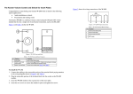
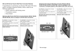
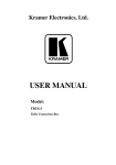
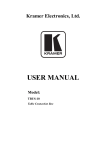
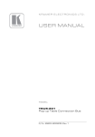
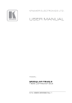
1
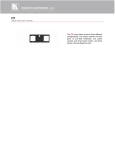
Installing the TBUS-5i Insert Plate
3.
The TBUS-5i Insert Plate (see Figure 1) is designed as a replacement for the
connecting surface of the TBUS-5, letting you install Kramer inserts and
modules1 according to your needs:
Unscrew the two power module screws that fasten the power module to the
connecting surface, keep the screws, and remove the power module from
below.
4.
Insert the power module into the designated opening (make sure you place
the power module in the correct position) on the Insert Plate and tighten
with the two power module screws.
5.
Place the Insert Plate inside the enclosure, and raise or lower the
connecting surface to the required height. Fasten the screws, and tighten
them in place.
Power Module
Opening
2 x Blank Plate
Power Module Screw
Cable
Pass-through
Figure 1: The Insert Plate
The inserts can be installed before or after installing the TBUS-5i unit.
To mount an insert, do the following:
1.
Unscrew the blank insert plate
2.
Place and align the insert under the opening, insert the two screws to fix the
insert in place, and tighten them.
To install the TBUS-5i Insert Plate, do the following:
1.
Remove the five height adjustment screws (see item 5 in Table 1 of the
TBUS-5 user manual) on the sides of the enclosure while supporting the
surface from underneath with your hand (keep the screws).
2.
Take out the connecting surface.
1
The complete list of Kramer inserts and interfaces is on our Web site at
www.kramerelectronics.com
Height
Adjustment
Screw
Figure 2: Removing the Height Adjustment Screws
TBUS-5i "Insert Plate"
Installation Instructions
For the latest information on our products and a list of Kramer distributors, visit our
Web site: www.kramerelectronics.com
Kramer Electronics, Ltd.
Web site: www.kramerelectronics.com
E-mail: [email protected]
P/N: 2900-001205 REV 1