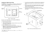
1
K R A ME R E LE CT R O N IC S L T D .
USER MANUAL
MODEL:
TBUS-201
Pop-up Table Connection Bus
P/N: 2900-300205 Rev 1
Contents
1
Introduction
1
2
2.1
Getting Started
Achieving the Best Performance
2
2
3
3.1
Overview
About HDMI—General Description
3
4
4
4.1
4.2
Defining the TBUS-201
The TBUS-201 Connecting Surface
Power Socket Options
5
6
7
5
5.1
5.2
5.3
5.4
Installing the TBUS-201
Cutting an Opening
Installing the Power Socket
Inserting the TBUS-201 through the Cut-Out Opening
Connecting the Cables
8
8
9
10
10
6
Technical Specifications
11
Figures
Figure 1: TBUS-201 Pop-up Table Connection Bus
Figure 2: Defining the Parts of the TBUS-201 Pop-up Table Connection Bus
Figure 3: TBUS-201 Connecting Surface
Figure 4: TBUS-201 Universal Power Socket Housing
Figure 5: Power socket installed
U
3
5
6
9
9
U
U
U
U
U
U
U
U
U
TBUS-201 – Contents
i
1
Introduction
Welcome to Kramer Electronics! Since 1981, Kramer Electronics has been
providing a world of unique, creative, and affordable solutions to the vast range of
problems that confront video, audio, presentation, and broadcasting professionals
on a daily basis. In recent years, we have redesigned and upgraded most of our
line, making the best even better!
Our 1,000-plus different models now appear in 11 groups that are clearly defined
by function: GROUP 1: Distribution Amplifiers; GROUP 2: Switchers and Routers;
GROUP 3: Control Systems; GROUP 4: Format/Standards Converters; GROUP 5:
Range Extenders and Repeaters; GROUP 6: Specialty AV Products; GROUP 7:
Scan Converters and Scalers; GROUP 8: Cables and Connectors; GROUP 9:
Room Connectivity; GROUP 10: Accessories and Rack Adapters and GROUP 11:
Sierra Video Products.
Thank you for purchasing the Kramer TBUS-201 Pop-up Table Connection Bus,
which is ideal for boardrooms, conference and training rooms!
TBUS-201 - Introduction
1
2
Getting Started
We recommend that you:
•
Unpack the equipment carefully and save the original box and packaging
materials for possible future shipment
•
Review the contents of this user manual
•
Use Kramer high-performance high-resolution cables
Go to http://www.kramerelectronics.com to check for up-to-date
user manuals, a complete list of Kramer wall plates and module
connectors, application programs, and to check if firmware
upgrades are available (where appropriate).
i
2.1
Achieving the Best Performance
To achieve the best performance:
•
Use only good quality connection cables to avoid interference, deterioration
in signal quality due to poor matching, and elevated noise levels (often
associated with low quality cables)
•
Do not secure the cables in tight bundles or roll the slack into tight coils
•
Avoid interference from neighboring electrical appliances that may adversely
influence signal quality
•
Position your Kramer TBUS-201 away from moisture, excessive sunlight and
dust
!
2
Do not place heavy objects on top of the TBUS-201.
TBUS-201 - Getting Started
3
Overview
The TBUS-201 is a furniture-mounted pop-up connection bus that is easily
installed into a table or podium top. The TBUS-201 interface enables you to
connect any equipment to systems installed in a room via the following passthrough connectors:
•
1 PC on a 15-pin HD connector
•
1 HDMI connector
•
1 stereo audio on a 3.5mm connector
•
1 Ethernet RJ-45 connector
When not in use, you can lower the TBUS-201 flush into the table. The example in
Figure 1 shows the TBUS-201 in a table or podium top with a universal power
socket.
Figure 1: TBUS-201 Pop-up Table Connection Bus
In addition, the TBUS-201 is:
•
Easily opened and closed by pressing down gently on the lid due to its tilting
angular construction, pneumatic lift and mechanical latching mechanism. It
can be raised (when in use) or lowered (when not in use)
•
Suitable for any of the following power sockets: for the USA, the UK,
Germany (the Europlug), Belgium-France, Switzerland, Italy, Australia,
Brazil, Israel, South Africa or “Universal” for use anywhere (see compatibility
restrictions in Section 4.2)
Order the power sockets separately from Kramer Electronics
TBUS-201 - Overview
3
3.1
About HDMI—General Description
High-Definition Multimedia Interface (HDMI) is an uncompressed all-digital audio/video
interface, widely supported in the entertainment and home cinema industry. HDMI
ensures an all-digital rendering of video without the losses associated with analog
interfaces and their unnecessary digital-to-analog conversions. It delivers the maximum
high-definition image and sound quality in use today. Note that Kramer Electronics
Limited is an HDMI Adopter and an HDCP Licensee.
HDMI, the HDMI logo and High-Definition Multimedia Interface are trademarks or registered
trademarks of HDMI licensing LLC.
In particular, HDMI:
•
Provides a simple interface between any audio/video source, such as a settop box, DVD player, or A/V receiver and video monitor, such as a digital flat
LCD / plasma television (DTV), over a single lengthy cable
SIMPLICITY - With video and multi-channel audio combined into a single cable, the
cost, complexity, and confusion of multiple cables currently used in A/V systems is
reduced
LENGTHY CABLE - HDMI technology has been designed to use standard copper cable
construction at up to 15m
•
Supports standard, enhanced, high-definition video, and multi-channel digital
audio on a single cable
MULTI-CHANNEL DIGITAL AUDIO - HDMI supports multiple audio formats, from
standard stereo to multi-channel surround-sound. HDMI has the capacity to support
Dolby 5.1 audio and high-resolution audio formats
•
Transmits all ATSC HDTV standards and supports 8-channel digital audio,
with bandwidth to spare to accommodate future enhancements and
requirements
•
Benefits consumers by providing superior, uncompressed digital video quality
via a single cable, and user-friendly connector
HDMI provides the quality and functionality of a digital interface while also supporting
uncompressed video formats in a simple, cost-effective manner
•
Is backward-compatible with DVI (Digital Visual Interface)
•
Supports CEC, two-way communication between the video source (such as a
DVD player) and the digital television, enabling new functionality such as
automatic configuration and one-button play
•
Has the capacity to support existing high-definition video formats (720p,
1080i, and 1080p, 2K and 4K), standard definition formats such as NTSC or
PAL, as well as 480p and 576p
4
TBUS-201 - Overview
4
Defining the TBUS-201
Figure 2: Defining the Parts of the TBUS-201 Pop-up Table Connection Bus
1
#
Feature
Black anodized or brushed
aluminum semi-automatic lid
2
Connecting Surface
See Section 4.1
3
Outer Rim
Fits over the table surface
4
Mini Latch
Enables the closing and opening of the lid by slightly
pressing it
5
Mounting Bracket Plates
For holding the brackets
6
Mounting Bracket Slits (four
sets on each side)
Insert the mounting brackets to the slits when installing
the TBUS-201
7
Rubber Protectors (2)
To ensure soft tightening to the table underside
8
Mounting Screws (2)
For securing the TBUS-201 to the table
9
Locking Butterfly Nuts (2)
Tighten to lock the mounting butterfly screw
10
Mounting Butterfly Nuts (2)
Tighten to secure the unit to the table surface
TBUS-201 - Defining the TBUS-201
Function
Covers the connecting surface, leaving the table surface
neat and tidy
5
4.1
#
11
Feature
Mounting Brackets (2 units)
Function
Place in the bracket slits after inserting the enclosure into
the table – for securing the unit to the table surface
12
Power Connector Lock
Secures the power cable so it does not accidently
disconnect when opening the lid
13
Pneumatic Piston
Enables automatic lifting and smooth closing of the lid
14
Power Socket Opening
Screw Holes (4)
For installing/replacing the power socket
The TBUS-201 Connecting Surface
Figure 3 defines the connecting surface and includes the universal power socket
(sold separately) for illustration purposes only:
Figure 3: TBUS-201 Connecting Surface
#
6
1
Feature
HDMI Connector
Function
Connect to an HDMI source
2
PC 15-pin HD Connector
Connect to a computer graphics source
3
AUDIO 3.5mm Mini Jack
Connects to an unbalanced stereo audio source
4
ETHERNET Connector
Connects to the PC or other Controller through computer
networking
5
Power Socket Opening
Suitable for various power sockets (see Section 4.2)
6
Connecting Surface
Pops up when gently pressing the lid
TBUS-201 - Defining the TBUS-201
4.2
Power Socket Options
A choice of power sockets is available for purchase in several versions, including
power sockets for the USA, Brazil, Germany (the Europlug), UK, Switzerland,
Belgium-France, Italy, South Africa, Israel and Australia. A “Universal” socket for
general use is also available (see the compatibility restrictions in the table below).
Note that the photos below are for illustration purposes only.
Power Socket
Type
Universal:
Power Specs
Description
TS-201U (80-000043)
Fully compatible with power plugs in the
UK, India, Italy and Denmark, as well as
with the 2-prong Europlug.
100-240V AC, 50/60Hz,
5A
Maximum 5A per power
outlet
Partially compatible (if the polarity is
reversed) with plugs in China, Switzerland,
Israel and the USA. The universal socket
does not supply grounding to plugs in Central
Europe and France and so you should order
country specific sockets instead.
Not compatible with South African plugs.
Power Socket
Type
USA:
Power Specs
Power
Socket Type
TS-201US (80-000046)
Italy:
100-240V AC, 50/60Hz, 5A
Maximum 5A per power
outlet
Germany and EU: TS-201DE (80-000044)
Belgium and
France:
Australia:
100-240V AC, 50/60Hz, 5A
TS-201AU (80-000050)
100-240V AC, 50/60Hz, 5A
100-240V AC, 50/60Hz, 5A
Maximum 5A per power
outlet
Maximum 5A per power
outlet
TS-201FR (80-000045)
Israel:
TS-201ZA (80-000052)
Maximum 5A per power
outlet
Brazil
100-240V AC, 50/60Hz, 5A
100-240V AC, 50/60Hz, 5A
Maximum 5A per power
outlet
TBUS-201 - Defining the TBUS-201
TS-201BR (80-000051)
100-240V AC, 50/60Hz,
5A
Maximum 5A per power
outlet
TS-201CH (80-000049)
TS-201IL (80-000053)
220V AC, 50/60Hz, 5A
Maximum 5A per power
outlet
Switzerland
TS-201IT (80-000047)
Maximum 5A per power
outlet
100-240V AC, 50/60Hz, 5A
South Africa
Power Specs
England
Maximum 5A per power
outlet
TS-201GB (80-000048)
100-240V AC, 50/60Hz, 5A
Maximum 5A per power
outlet
7
5
Installing the TBUS-201
To install the TBUS-201 perform the following steps:
1. Cut an opening in the table (see Section 5.1).
2. Install the power socket (see Section 5.2).
3. Insert the TBUS-201 through the cut-out opening (see Section 5.3).
4. Connect the cables (see Section 5.4).
5.1
Cutting an Opening
The cardboard cutout template (supplied) defines the surface you have to cut out
to install your TBUS-201.
i
The thickness of the table should be 3in (76mm) or less.
Before cutting the opening, confirm the dimensions of the cutout template and
make sure that they have not changed.
Mark the area to cut and then cut out the relevant part of the wooden surface in
which you want to insert the TBUS-201.
!
8
Take care not to damage the table. Kramer Electronics is not
responsible for any damage caused to the table.
TBUS-201 - Installing the TBUS-201
5.2
Installing the Power Socket
Figure 4 shows an example of the Universal power socket housing which is one of
the optional power sockets for the TBUS-201, see Section 4.2.
Figure 4: TBUS-201 Universal Power Socket Housing
To install the power socket:
1. Close the TBUS-201 lid.
2. Carefully insert the power socket housing so that the power socket fits into
the power socket opening on the connecting surface and the four standoffs
fit the four screw holes on the TBUS-201.
When positioned correctly, the IEC socket faces downwards.
3. Screw the four screws included in the power socket kit into the designated
holes to fix the power socket housing in place (see Figure 5).
Figure 5: Power socket installed
4. Unscrew the power connector lock.
TBUS-201 - Installing the TBUS-201
9
5. Connect the IEC power cord to the IEC socket.
6. Insert the power cord into the power connector lock and tighten the screw
(see Figure 2, item 12) to secure the power cable.
5.3
Inserting the TBUS-201 through the Cut-Out Opening
To install the TBUS-201, do the following:
1. Carefully insert the unit into the prepared opening.
2. Take the support brackets under the table and place them into the support
bracket grooves at the desired height (on both the front and rear sides of the
unit).
3. Make sure that the upper outer rim is situated parallel to the edge of the
table.
4. Insert the table securing screw through the holes in the support brackets and
tighten them until they reach the table surface (from underneath).
5.4
Connecting the Cables
1. Connect the appropriate cables from underneath.
2. Secure the cables.
Do not keep the cord too tight or too loose.
Once you have connected the unit to the mains power and connected the proper
cables, you may use the unit.
10
TBUS-201 - Installing the TBUS-201
6
Technical Specifications
PORTS:
POWER SOURCE
(AC power limits):
1 HDMI connector, 1 Ethernet RJ-45 connector,
1 15-pin HD connector, 1 3.5mm mini jack
Power Socket Assemblies
Universal
100-240V AC, 50/60Hz, 5A
Maximum 5A per power outlet
Fully compatible with power plugs in the UK, India, Italy
and Denmark, as well as with the 2-prong Europlug.
Partially compatible (if the polarity is reversed) with
plugs in China, Switzerland, Israel and the USA. The
universal socket does not supply grounding to plugs in
Central Europe and France (you should order country
specific sockets instead).
Not compatible with South African plugs.
FUSE RATING:
USA
100-240V AC, 50/60Hz, 5A
Maximum 5A per power outlet
Germany and EU
100-240V AC, 50/60Hz, 5A
Maximum 5A per power outlet
Belgium and France
100-240V AC, 50/60Hz, 5A
Maximum 5A per power outlet
Italy
100-240V AC, 50/60Hz, 5A
Maximum 5A per power outlet
Australia
100-240V AC, 50/60Hz, 5A
Maximum 5A per power outlet
Israel
220V AC, 50/60Hz, 5A
Maximum 5A per power outlet
South Africa
220V AC, 50/60Hz, 5A
Switzerland
220V AC, 50/60Hz, 5A
England
220V AC, 50/60Hz, 5A
Brazil
220V AC, 50/60Hz, 5A
Maximum 5A per power outlet
Maximum 5A per power outlet
Maximum 5A per power outlet
Maximum 5A per power outlet
T 6.3A 250V
OPERATING TEMPERATURE RANGE: +5 to +45 Deg. Centigrade
OPERATING HUMIDITY RANGE:
10 to 90% RHL, non-condensing
STORAGE TEMPERATURE RANGE:
-20 to +70Deg. C.
STORAGE HUMIDITY RANGE:
5 to 95% RHL, non-condensing
DIMENSIONS:
Including the outer rim: 14.5cm x 13.2cm x 17.3cm
(5.71" x 5.2" x 6.81") W, D, H
Without the outer rim: 13.3cm x 12.0cm x 17.3cm (5.24"
x 4.72" x 6.81") W, D, H
WEIGHT:
0.85kg (1.87lbs) approx.
1.2kg (2.65lbs) approx. with mounting brackets
ACCESSORIES:
Cardboard template
OPTIONS:
Power socket kits, power cord
Specifications are subject to change without notice at http://www.kramerelectronics.com
TBUS-201 - Technical Specifications
11
For the latest information on our products and a list of Kramer distributors,
visit our Web site where updates to this user manual may be found.
We welcome your questions, comments, and feedback.
Web site: www.kramerelectronics.com
E-mail: [email protected]
!
SAFETY WARNING
Disconnect the unit from the power
supply before opening and servicing
P/N: 2900- 300205
Rev: 1