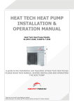
Download Alliance Domestic R410 HPWH Technical Manual
Transcript
AA –HP410-2011-02
Alliance Cycle-Heating Domestic Heat Pump Water Heater Technical Manual
Alliance Cycle-Heating Domestic
Heat Pump Water Heater
R410 - Technical Manual
Applicable Models:
ALLWH3.2kW R410
ALLWH5.0kW R410
ALLWH7.2kW R410
Alliance reserves the right to discontinue, or change at any time, specifications or designs without notices
and without incurring obligations.
1
AA –HP410-2011-02
Alliance Cycle-Heating Domestic Heat Pump Water Heater Technical Manual
Contents
Part 1 General Information ....................................................................... 3
1. Model Names of Outdoor Units ........................................................................... 4
2. External Appearance ............................................................................................ 4
3. Nomenclature........................................................................................................ 5
4. Features ................................................................................................................ 6
Part 2 Outdoor units .................................................................................. 7
1. Specifications ....................................................................................................... 8
2. Relationship between Outdoor Ambient Temperature and Unit Capacity ..... 10
3. Relationship between Outdoor Ambient Temperature and COP .................... 12
4. Relationship between Outdoor Ambient Temperature and Outlet Water
Temperature ........................................................................................................ 14
5. Main Unit Foundation Bolt Dimensions ............................................................ 14
6. Service Space ..................................................................................................... 15
7. Wiring Diagrams ................................................................................................. 15
8. Exploded View .................................................................................................... 17
9. PCB Explanation……………………………………………………………………….21
Part 3 Installation .................................................................................... 22
1. Precautions ......................................................................................................... 23
2. Installation information ...................................................................................... 24
3. Accessories ........................................................................................................ 25
4. System diagram of the whole unit .................................................................... 26
5. Electrical wiring ................................................................................................ 267
6. Outdoor Unit Installation .................................................................................... 30
7. Water Pipe Installation ....................................................................................... 31
Part 4 Trial Operation .............................................................................. 33
1. Confirmation before the trial operation ............................................................ 34
2. Water Tank water resupplying and Water Pipe and Pump Air Exhaust
(Artesian Pressure Water Tank) ........................................................................ 35
3. Wire Controller ALL REMOTE WATER .............................................................. 36
4. Startup Process .................................................................................................. 36
5. Trial Operation Check ........................................................................................ 37
6. Corresponding Operation Explanation............................................................. 37
7. Error Code Explanation and Analysis ............................................................ 378
8. Spot Check .......................................................................................................... 39
2
AA –HP410-2011-02
Alliance Cycle-Heating Domestic Heat Pump Water Heater Technical Manual
Part 1
General Information
1. Model Names of Outdoor Units ...................................... 4
2. External Appearance ....................................................... 4
3. Nomenclature ................................................................... 5
4. Features ............................................................................ 6
3
AA –HP410-2011-02
Alliance Cycle-Heating Domestic Heat Pump Water Heater Technical Manual
Model Names of Outdoor Units
Outdoor Units
Model name
Dimension (mm)
Net/Gross weight (kg)
Power supply
ALLWH3.2 KW
Width: 790
Height: 736
Depth:260
54/57
220~240V-1ph-50Hz
ALLWH5.0 KW
Width: 790
Height: 736
Depth:260
62/66
220~240V-1ph-50Hz
ALLWH7.2 KW
Width: 845
Height: 945
Depth:335
81/86.5
220~240V-1ph-50Hz
External Appearance
Outdoor unit
ALLWH3.2 KW
ALLWH5.0 KW
ALLWH7.2 KW
4
AA –HP410-2011-02
Alliance Cycle-Heating Domestic Heat Pump Water Heater Technical Manual
Nomenclature
Household water heating unit
1 - 2
3 - 4 / 5
6
7
8
9 10 - 11
Design code
Refrigerant code
Water supply pump lift code
Other functions code
Power supply specification code
Heating mode code
Water tank volume, unit: L
Rated hot water output, unit: 100 W
Installation type code
Water heating unit code
Export model code
5
AA –HP410-2011-02
Alliance Cycle-Heating Domestic Heat Pump Water Heater Technical Manual
4. Features
4.1 Safety
a.
Ensure there is isolation between water and electricity to avoid possibility of electric shocks
b.
Unit not to be mounted adjacent to fuel tanks or pipes to avoid potential danger from oil leakage,
fire, explosion etc.
4.2 Double wall heat exchanger built in main unit
4.3 R410a gas, Environmental protection.
a.
No discharge of poisonous gas.
b.
No pollution to atmosphere and environment
4.4 Max. water temperature: 60℃
℃.
4.5 Rapid heating of water.
4.6 Easy operation and automatic control.
The system can be controlled simply through the wired controller.
Automatic start-up, shutdown and automatic defrosting saves extra manual operation.
4.7 High efficiency and energy-saving.
The unit uses heat pump principle, which absorbs heat from outdoor air and produces hot water. Thermal
efficiency can be approximately 4.0.
4.8 All-weather running.
Designed to operate between temperatures ranging from -7 to 43℃, the Alliance heat pump heats at night
and during periods of overcast sky, rain and snow.
4.9 Convenient installation and maintenance
The quadrate type is highly compact and can be easily installed in narrow areas
4.10 Wilo water pump built into the main unit.
4.11CE approval
6
AA –HP410-2011-02
Alliance Cycle-Heating Domestic Heat Pump Water Heater Technical Manual
Part 2
Outdoor units
1. Specifications .................................................................. 8
2. Relationship between Outdoor Ambient
Temperature and Unit Capacity .................................... 10
3. Relationship between Outdoor Ambient
Temperature and COP ................................................... 12
4. Relationship between Outdoor Ambient
Temperature and Outlet Water Temperature ............... 14
5. Main Unit Foundation Bolt Dimensions ....................... 14
6. Service Space................................................................. 15
7. Wiring Diagrams ............................................................ 15
8. Exploded View ............................................................... 17
9. PCB explanation ............................................................ 21
7
AA –HP410-2011-02
Alliance Cycle-Heating Household Heat Pump Water Heater Technical Manual
1. Specifications
Model
Power supply
Ph-V-hz
ALLWH3.2 KW
ALLWH5.0 KW
ALLWH7.2 KW
1-220-50
1-220-50
1-220~240-50
4.3
6.5
1.11
1.6
Capacity
kW
Input
kW
Rated
current
A
3.7
6
Max. input consumption
kW
1.55
1.85
2.55
Max. input current
A
7.5
6
11.1
Starting current
A
19.2
27.4
36.8
Model
PA118M1C-4FZ2
PA160X2C-4FT
PA240X2CS-4KU1
Type
Rotary
Rotary
Rotary
Brand
Toshiba
Toshiba
Toshiba
Supplier
MIDEA-TOSHIBA
(Guangdong)
MIDEA-TOSHIBA
(Guangdong)
MIDEA-TOSHIBA
(Guangdong)
2.88
3.91
5.8
1.03
1.35
1.99
Water
Heating
Compressor
0.81
7.3
Capacity
kW
Input
kW
Rated
current(RLA)
A
4
5.8
9.3
Locked rotor
Amp(LRA)
A
19.2
27.4
36.8
INNER
INNER
INNER
Thermal
protector
outdoor fan
motor
3.0
Capacitor
uF
25
35
50
Refrigerant
oil
ml
350
480
750
Model
YDK36-6R-1
YDK36-6R-1
YDK65-6N
Brand
Welling
Welling
Welling
Input
kW
0.08
0.08
0.125
Capacitor
uF
3.5
3.5
3
Speed(hi/lo)
r/min
775/510
775/510
830/450
1.5
2
2
25.4X22
25.4X22
1.8
1.8
1.4
Hydrophilic
aluminium
Hydrophilic
aluminium
Hydrophilic
aluminium
Ф9.52 innergroove
tube
Ф9.52 innergroove
tube
Ф7.94 innergroove
tube
772X484X44
772X484X44
802X660X44
5
5
5
a.Number of
rows
b.Tube
pitch(a)x row
pitch(b)
mm
c. Fin
spacing
mm
outdoor coil
d.Fin type
e.Tube outer
dia.and type
mm
f.Coil length
x height x
width
mm
g.Number of
circuits
8
22X22
AA –HP410-2011-02
Alliance Cycle-Heating Household Heat Pump Water Heater Technical Manual
Outdoor air flow
m3/h
2000
2000
3200
Outdoor noise level
dB(A)
49
55
55
Dimension
(W*H*D)
mm
790×736×260
790×736×260
840×940×324
Packing
(W*H*D)
mm
905×807×355
905×807×355
965×1009×395
Net/Gross
weight
kg
54/57
62/66
81/86.5
Refrigerant type/Quantity
kg
R410A/0.95
R410A/1.2
R410A/1.3
Design pressure
MPa
4.4/2.2
4.4/2.2
4.4/2.2
Liquid/ Gas
side
mm
/Ф9.52
/Ф9.52
Ф7.94/Ф12.7
Max. pipe
length
(water)
m
5
5
Outdoor
unit
Refrigerant
piping
5
Max. difference in level of
the unit and tank
m
3
3
3
Ambient temp
℃
-7℃-43℃
-7℃-43℃
-7℃-43℃
Diameter,
water inlet
pipe
mm
DN20
DN20
DN20
Diameter,
water outlet
pipe
mm
DN20
DN20
DN20
Diameter,
water
circulating
pipe
mm
DN20
DN20
DN20
KJR-26B/GWE
KJR-26B/GWE
KJR-26B/GWE
0.86m
1.12
40℃~60℃
40℃~60℃
water
pipe
Wire Controller
3
Hot Water Yield
m /h
Water outlet temp.
℃
0.516
40℃~60℃
Remark:
1. The test conditions: outdoor temp.7.0/6.0℃ (DB/WB),
inlet water temp. 30℃, outlet water temp. 35℃.
2. The operation range:-7℃-43℃.
3. Specifications may change due to product improvements. Please refer to the nameplate.
9
AA –HP410-2011-02
Alliance Cycle-Heating Household Heat Pump Water Heater Technical Manual
2. Relationship between Outdoor Ambient Temperature and Unit Capacity
Heat Pump Models:
ALLWH3.2 KW
ALLWH5.0 KW
10
AA –HP410-2011-02
Alliance Cycle-Heating Household Heat Pump Water Heater Technical Manual
ALLWH7.2 KW
11
AA –HP410-2011-02
Alliance Cycle-Heating Household Heat Pump Water Heater Technical Manual
3. Relationship between Outdoor Ambient Temperature and COP
Heat Pump Models:
ALLWH3.2 KW
ALLWH5.0 KW
12
AA –HP410-2011-02
Alliance Cycle-Heating Household Heat Pump Water Heater Technical Manual
ALLWH7.2 KW
13
AA –HP410-2011-02
Alliance Cycle-Heating Household Heat Pump Water Heater Technical Manual
4. Relationship between Outdoor Ambient Temperature and Outlet
Water Temperature
Note:
The unit outlet water temperature is under full-automatic control and the water tank is the pressure type.
When hot water is being drawn off, cold water will enter the water tank, thus decreasing the temperature.
Taking into account usage patterns, hot water amount (above 40 ℃) should account for 90% of the tank
volume.
14
AA –HP410-2011-02
Alliance Cycle-Heating Household Heat Pump Water Heater Technical Manual
5. Main Unit Foundation Bolt Dimensions
B
A
Throu gh ho le (12×22 li nea r hole )
C
MODEL
D
A
B
C
D
ALLWH3.2 KW
563
295
100
790
ALLWH5.0 KW
563
295
100
790
ALLWH7.2 KW
560
335
140
845
6. Service Space
15
AA –HP410-2011-02
Alliance Cycle-Heating Household Heat Pump Water Heater Technical Manual
7. Wiring Diagrams
ALLWH3.2
ALLWH3.2KW ALLWH5.0 KW ALLWH7.2 KW
1.5HP
ALLWH5.0
2HP
ALLWH7.2
16
AA –HP410-2011-02
Alliance Cycle-Heating Domestic Heat Pump Water Heater Technical Manual
8. Exploded View
ALLWH3.2 KW &
ALLWH5.0 KW
7
4
15
10
19
3
27
29
17
18
20
35
21
22
12
23
16
5
24
25
26
30 30.1
32 32.1
32.2 32.3
32.4 32.5
32.6
6 6.1
9
37
11
31
28
36
14
2
35
17
13
1
6.2
AA –HP410-2011-02
Alliance Cycle-Heating Domestic Heat Pump Water Heater Technical Manual
32.6
32.3
32.2
32.1
32.4
32.5
30.1
No.
1
2
3
4
5
6
6.1
6.2
7
8
9
10
11
12
13
14
15
16
17
18
19
20
21
22
23
Part
Name
Rear right clapboard ass'y
Front panel
Top cover
Motor bracket
Big handle
Throttle ass'y
Electronic expansion valve
EEV solenoid
Rear net
Condenser ass'y
Grille
Axial flow fan
Base ass'y
Drain pipe adapter
Middle partition plate
Side board
Side board
Adapter ass'y
Holder Ⅰ
Holder Ⅱ
Motor
Shield pump ass'y
Temp sensor
Temp sensor
Temperature sensor
Quantity
1
1
1
1
1
1
1
1
1
1
1
1
1
2
1
1
1
1
1
1
1
1
1
1
2
No.
24
25
26
27
28
29
30
30.1
31
32
32.1
32.2
32.3
32.4
32.5
32.6
33
33.1
33.2
33.3
33.4
34
35
36
37
18
Part
Name
Temp.sensor ass'y
Compressor electric heater
Discharge temp sensor ass'y
Partition board
Waterproof net ass'y
Shell and tube exchanger ass'y
Terminal installation box
Wire joint
Compressor
E-part box ass'y
Motor capacitor
Compressor capacitor
Main control board ass'y
Relay
Middle connection board ass'y
Transformer
4-way valve ass'y
Four-way electro-magnetic reversing valve
Solenoid
Pipe joint
Pressure controller
Left supporter
Strainer
Drain hose
Wire controller
Quantity
1
1
1
1
2
1
1
1
1
1
1
1
1
1
1
1
1
1
1
2
1
1
1
1
1
AA –HP410-2011-02
Alliance Cycle-Heating Domestic Heat Pump Water Heater Technical Manual
ALLWH7.2kW
19
AA –HP410-2011-02
Model selection
(Set before out from factory)
S1
2
1
3
External overload protection
device of compressor
202090590098
ON
ON
12
4
Alliance Cycle-Heating Domestic Heat Pump Water Heater Technical Manual
1HP
RSJF-35/CN1-A
2
1.5HP
RSJF-50/CN1-A
Red
12
ON
ON
2HP
RSJF-65/CN1-A
0.8HP
RSJF-28/CN1-A
12
White
12
FOR CE
C N24 CN25
T5
T8
RT1
RT6
RTp
XS8
Condenser Temp.Sensor
Hi-pressu re pro tection
R
Blue
Compressor
CN7
TRA NS O UT
Main Control Board
White
RT3
Yellow/Green
Transformer
CN8
PO WER1
QUERY
C N21
Tp
Temp. Sensor of
compressor air exha ust
Outdoor Temp. Se nsor
S1
C N22
T6
Water inlet Temp. Sensor
at bushing
C
COM P.F
CN 23
T1
Temp. Sensor at refrigerant
outlet of bushing
S
CT1
CN 10
CN 9
C OMIN COMOUT
Blue
White
CN20
XP8
Fan
Cap acity
Black
Yellow
RY7
CN 28
PR O_H
H_PRO
CN 27
PR O_L
C N1
CN2
C N2
White
Wh ite
L
CN6
P OWER
CN5
蓝
TRAN S IN
CN 4
White
N
Pump
4-WAY
Black
Fan
Capacity
REVERSE
XP5
XS5
HEATCOM P
EEV
FAN_L
FAN_H
簜
Note:
1. The forcing switch at the main board inside of
the unit is the open switch for the pump that is
used for operation testing, using by no one but
professional engineer.
2. When wiring the compressor, please pay
attention to the model RSJF-35/CN1-A that
installed an external overloadpro tector, which
shown in above broken frame.
For other models without the part of broken
frame, please joint the corresponding terminals
directly, when wiring the comp ressor.
The color in bracket is the
fa n motor wire color of 2
horsepower u nit.
Red
Brown(Wh ite)
Fan
XP10
P(2)
P(3)
P(8)
P(9)
N
P(4)
N
HEAT
Black(Black)
FAN
Red(Brown)
Brown
Mid-termina ls
panel
Brown
P(2)
CT1
L
Pump
P(1)
Reserved
CRANK Compressor
heating ban d
Lo-wind
PUMP
FAN-L
4-way
Yello w/Green
X T2
L
FAN-H
4-WAY
Black
Red
Red
Hi-wind
Red
Blue
Yellow(Green)
Relay 1
Compressor
White
Yellow
Electron
expanding
valve 1
Blue(White)
Brown
Yellow
P(5)
P(6)
N
N
Red
FAN_H
Hi-wind
FAN_L
Lo-wind
P(3)
P(7)
N
N
XS10
Blue
White
Red
Brown
Black
Yellow
T5
A B P Q E
P le a s e c o n n e c t w ir e
c o n tr o lle r w ith
at ta c he d 5- c or e
s h ie ld ed w ir e.
No.
1
2
2.1
2.2
2.3
2.4
2.5
2.6
2.7
3
4
5
6
7
8
9
10
12
13
14
15
16
17
18
18.1
18.2
Te m p . s e n s o r
in w a te rta n k .
Please connect
with the attached
T5 temp. sensor.
Part
Power supply
220V~50Hz
Please apply the attached
electric leakage protection
cable!
Name
Cover
E-part box ass'y
Main controller ass'y
Motor capacitor
Compressor capacitor
Relay
Middle connection board ass'y
Transformer
E-part box
Side board
Expansion vessel connection pipe ass'y
water inlet pipe ass'y
Water inlet ass'y
Shield pump ass'y
Electronic expansion valve ass'y
Drain pipe adapter
Left holder
Terminal installation box
Rear right clapboard
Front right clapboard ass'y
Base ass'y
Partition board ass'y
Compressor
4-way valve ass'y
4-way valve
Pressure controller
4-WAY
P(1)
N o t e : Th e r ig h t c o m p o n e n t s in t h e f ra m e a re
jo in t e d t o th e c o rr e s p o n d in g in s e rt p a t c h e s in
t h e p in b o a rd ( Jo in te d b e f o r e s h ip m e n t ).
Quantity
No.
19
20
21
22
23
24
25
26
27
28
29
30
31
32
33
34
35
36
37
38
39
40
41
42
43
44
46
1
1
1
1
1
1
1
1
1
1
1
1
1
1
1
2
1
1
1
1
1
1
1
1
1
1
20
Heatin g band
Part
Red
P(4)
N
P(5)
CRANK
Boosting pump
4-way
4-way valve
CRANK
N
Name
Axial flow fan
Grille
Motor
Front panel
Motor bracket ass'y
Expansion vessel
Up partition board ass'y
Condenser ass'y
Expansion vessel clap
Side board
Tube-in-tube heat-exchanger
Name Plate
Waterproof net ass'y
Drainage water pipe ass'y
Bracket
Rear net frame
Rear net
EEV solenoid
4-Ways valve solenoid
Small handle
Drain hose
Wire controller
Temperature sensor
Temp sensor
Temp sensor
Temp.sensor ass'y
Compressor electric heater
M
Blue
PUMP
N
Yellow/green
Quantity
1
1
1
1
1
1
1
1
1
1
1
1
2
1
1
1
1
1
1
1
1
1
2
1
1
1
1
AA –HP410-2011-02
Alliance Cycle-Heating Domestic Heat Pump Water Heater Technical Manual
9. PCB explantation
21
AA –HP410-2011-02
Alliance Cycle-Heating Domestic Heat Pump Water Heater Technical Manual
Part 3
Installation
1. Precautions .................................................................... 23
2. Installation information ................................................. 24
3. Accessories .................................................................... 25
4. System schematic diagram of whole unit ……………..26
5. Electrical wiring ........................................................... 267
6. Outdoor Unit Installation ............................................... 30
7. Water Pipe Installation................................................... 31
22
AA –HP410-2011-02
Alliance Cycle-Heating Domestic Heat Pump Water Heater Technical Manual
1. Precautions
Be sure to conform to local, national and international laws and regulations.
Read "PRECAUTIONS" carefully before installation. They include important safety items.
Keep this manual with the owner's manual for future reference.
The safety precautions listed here are divided into two categories. As these are important, please read them
both carefully.
WARNING:
(Failure to observe the warnings below could result in fatal injury)
Only trained and qualified service personnel are to install, repair or maintain the equipment.
Improper installation, repair or maintenance may result in electric shock, short-circuits, leaks, fire or other
damage to the equipment.
The unit must be installed strictly according to these installation instructions.
Defective installation could cause water leakage, electric shock or fire.
Ensure that the attached accessories and specified parts are used for installation, otherwise water leakage,
electric shock or fire may result.
The unit is to be installed on a suitably strong wall able to withstand the unit's weight. An improperly done
installation may result in damage to the unit or the unit becoming detached from its mountings.
The enclosure of the appliance is to be marked by word or symbols, indicating direction of fluid flow.
For electrical work, local and national wiring standards are to be adhered to. An independent circuit and
single outlet must be used.
Improper connection or fixing may cause overheating or fire at the connection point.
Routing of wiring must be properly carried out, and the control board cover fixed in place. An improperly
fixed control board cover may cause overheating at terminal connection points and fire or electric shock.
If the supply cord is damaged, it must be replaced by the service agent or other qualified person in order to
avoid a potential hazard.
An all-pole disconnection device which has at least 3mm separation distance in all poles and a residual
current device (RCD) with a rating above 10mA must be incorporated in the fixed wiring according to
national regulations.
In areas prone to strong winds, typhoons or earthquakes, consideration must be taken into account during
installation.
If any refrigerant leak occurs during installation, ventilate the area immediately.
As the temperature of refrigerant pipe will be high, please keep the interconnection cable away from it.
After completion of installation, check for any leakage of refrigerant.
Toxic gas may be produced if refrigerant leaks into an enclosed room and comes into contact with a source
of fire such as a fan heater, stove or cooker.
CAUTION
Failure to observe the cautions listed below may result in injury, or damage to the equipment.
After the installation is completed, make sure that the unit is operating properly during the trial operation.
Please instruct the customer on how to operate the unit and keep it maintained. Also, inform customers to
keep this manual for future reference.
23
AA –HP410-2011-02
Alliance Cycle-Heating Domestic Heat Pump Water Heater Technical Manual
The water heater must be earthed.
Do not connect the earthing wire to gas or water pipes, lightning rod or a telephone earthing wire.
Incomplete earthing may result in electric shocks.
Be sure to install an earth leakage breaker. Failure to install an earth leakage breaker may result in electric
shocks.
First connect the outdoor unit wires before connecting the indoor unit wires.
Do not connect the power supply to the units until final wiring and piping of the units is done.
Be sure to install drain piping in order to ensure proper drainage, and insulate piping in order to prevent
condensation. Improper drain piping may result in water leakage and property damage.
Young children should be supervised to ensure that they do not play with the appliance.
Don't install the heat pump in the following locations:
Where petrolatum exists.
Directly exposed to salty air (near the coast).
Where caustic gas (e.g sulfide) exists in the air (near a hot spring).
In areas of excessive vibration (e.g. as can occur in factories).
Inside buses or cabinets.
Inside kitchens
Where strong electromagnetic waves exist.
In close proximity to inflammable materials, gas, acids or evaporating alkaline liquids.
2. Installation information
Before installation, please read this manual first.
The HPWH must be installed by qualified personnel.
When installing the tank and piping, please follow this instruction manual as strictly as possible.
If the HPWH is installed on a metal part of the building, it must be electrically insulated according to the
relevant standards of electrical appliances.
When all the installation work is finished, turn on the power only after a thorough check.
This manual is subject to changes due to technological improvement without further notice.
INSTALLATION ORDER
Select the location
Install the outdoor unit;
Install the water tank
Install the connecting pipe
Connect the drain pipe
Connect wiring
Test operation.
24
AA –HP410-2011-02
Alliance Cycle-Heating Domestic Heat Pump Water Heater Technical Manual
3. Accessories
Please check whether all the following fittings are included. If any are missing, be sure to obtain them before
proceeding with installation.
Name
Qty
Application
1. Installation and User Manual
1
——
2. Y type filter
1
Inlet water filter
3. Wire control assembly
1
Controls the units and display units status
4. Seal ring
1
Seals the drain pipe
5. Drain connecting pipe
1
Main unit condensed water drainage
6. Water tank temperature sensor
1
Water tank temperature check
Cautions on remote controller installation:
Treat controller with care; do not mishandle or drop it.
Before installation, operate the remote controller to determine its location in terms of reception range.
Keep the remote controller at least 1m apart from the nearest TV set or stereo equipment (necessary to
prevent image disturbances or noise interference.)
Do not install the remote controller in a place exposed to direct sunlight or close to a heating source, such as
a stove.
Ensure that batteries are loaded correctly in terms of positive and negative poles.
This manual is subject to changes due to technological improvement without further notice.
25
AA –HP410-2011-02
Alliance Cycle-Heating Domestic Heat Pump Water Heater Technical Manual
3. System schematic diagram of whole unit
Models: ALLWH3.2 KW ALLWH5.0 KW ALLWH7.2 KW
26
AA –HP410-2011-02
Alliance Cycle-Heating Domestic Heat Pump Water Heater Technical Manual
5. Electrical wiring
5.1 Attention
•
•
•
•
•
•
•
The water heater is to be connected correctly in terms of power supply and rated power voltage.
The power supply circuit of the water heater must be earthed. The power cord is to have a suitable earth
and all external earthing cables are to be properly connected.
The construction of the wiring should be carried out by professionals in accordance with the circuit
diagram.
Earth leakage protection devices must be in accordance with the requirements of relevant national
technical standards.
The power cord and the signal line should be laid in such a manner so as to not interfere with each other,
and should not come into contact with the connecting pipe and the valves.
The unit is not equipped with a power cord. Please refer to the prescribed power specifications for
selecting the power cord, whilst connecting between two lines is not allowed.
Check whether all the connections are correct before powering the unit.
.
5.2 Power Specification
2
Item
Power
Supply
Model
Min. wire size(mm )
(Metal pipe &synthetic resin pipe wire)
Size
(Continuous
Earthing
length≤30m)
Manual
Switch(A)
Capacity
Fuse
RCCB
Model
ALLWH3.2 KW
ALLWH5.0 kW
ALLWH7.2 KW
220~240V,
50Hz
1.5
1.5
20
15
30mA, below
0.1 sec
LBC-16-1-CP
220~240V,
50Hz
2.5
2.5
30
25
30mA, below
0.1 sec
LBC-16-1-CP
Note:
1 The power cord type designation is H07RN-F.
2 Wire size and continuous wire length in the table above only available for the case of the voltage
decreasing range not exceeds than 2%.
3 If the continuous wire length value larger than the one of the table, please choose its size in compliance
with the relevant rules.
.
5.3 Cable Size and Pieces
Name
Pieces
Length
Cable Diameter
2.5 mm2
Water pump power cord
2-core
≤ 50 m
Electric-heating power cord
2-core
≤ 50 m
Circulating water pump power cord
Four-section type water volume
controller cord
Communication cord (shielded)
3-core
≤ 50 m
2.5 mm2
2.5 mm2
5-core
≤ 20 m
1.0 mm2
5-core / 3-core
≤ 50 m
Water flow switch cord
2-core
≤ 50 m
0.75 mm2
1.0 mm2
Water pressure switch cord
2-core
≤ 50 m
Solenoid valve cord
3-core
≤ 50 m
1.0 mm2
1.5 mm2
Note: When the power cord and the controlling wire run parallel, please place each wire in its respective
tube, leaving suitable distance between the lines.
27
AA –HP410-2011-02
Alliance Cycle-Heating Domestic Heat Pump Water Heater Technical Manual
5.4 Power supply wiring.
A. Power supply equipment application
Power supply equipment
Leakage
protector
(with leakage protector)
(b)
Earthing
(a) Manual
switch
Earthing
Junction
box
Earthing
(b
)
Earthing
Earthing
Earthing
Note: Although there is a leakage protector in the electric control box of the unit, for reasons of additional
security it is required that a leakage protector be installed in the external electric control box of the unit
according to the above diagram.
B. Cable diameter selection
The power supply wiring refers to the wiring to the main line (a) of junction box and the wiring (b) to the
power supply equipment. Please select the cable diameter according to the following methods
1)
Diameter of the main line (a):
Determine from the power supply specification table according to the sum of horsepower of the unit.
2)
Diameter of the wiring from the junction box to the power supply equipment:
When the water heaters are less than 5 sets, the diameter of the wiring from the junction box to the power
supply equipment should be the same as the main line (a); when the water heaters are more than 6 sets, the
power supply equipment should have two sets of electric control boxes and the diameter should be
determined from the power supply specification table according to the sum of horsepower of the units
connected via the electric control box.
28
AA –HP410-2011-02
Alliance Cycle-Heating Domestic Heat Pump Water Heater Technical Manual
5.5 Electrical connection diagram.
Electrical Wiring diagram for Models :ALLWH3.2 KW, ALLWH5.0 KW, ALLWH7.2 KW
29
AA –HP410-2011-02
Alliance Cycle-Heating Domestic Heat Pump Water Heater Technical Manual
6. Outdoor Unit Installation
Installation space requirement
a.
Ensure there is sufficient space for the maintenance of outdoor unit
b.
A distance of no less than 200mm should be maintained between the bottom of the outdoor unit and the
ground or bracket for the installation of the duct pipe.
Host Unit
Host
Unit
Unit air outlet
It is strictly prohibited to block
the unit air outlet
c.
Distance between anchor bolt is shown as follows
Model
ALLW3.2Kw
ALLW5.0Kw
ALLW7.2Kw
A
563
563
560
B
295
295
335
C
100
100
140
30
D
790
790
845
E
275
275
335
F
765
765
945
AA –HP410-2011-02
Alliance Cycle-Heating Domestic Heat Pump Water Heater Technical Manual
7. Water Pipe Installation
7.1 Installation material preparative
Installation Materials
Name
Qty
Specification and Usage
Water pipe, flexible joint
Decided by the project needs.
Metal, non-metal composite pipes; PPR pipe,
polyethylene-aluminium composite pipeline, etc.
Hydraulic gauge
One per unit
Scale 0.2bbar; Measure 8bar
Ball valve
One per unit
Water tank inlet pipeline
Insulation material for hot water
pipeline
According to the length of the
hot water pipeline.
Heat preservation material for hot water pipeline
Insulation
pipeline
According to the length of the
refrigerant pipeline.
Insulation
One
Power supply connection; Install the wired
controller, ammeter, etc.
material for refrigerant
Electric Control Box
material for refrigerant pipeline
7.2 Remarks:
a.
The pipe length between host unit and water tank should be a maximum of 5m, and the height
difference a maximum of 3m. If exceeded, this could lead to overloaded water pump, insufficient
circulation of water and affect high pressure protection of host unit.
b.
Aluminium-plastic or PPR pipes are recommended for connection and should be wrapped with a heat
insulation layer and protection layer such as thin Al sheet and plain galvanized steel sheet in case of
exposure.
c.
Connection and installation of the unit pipeline:
When connecting the inlet and outlet pipeline of the unit, use two pipeline grips to secure the two parts to be
connected, to ensure that inlet and outlet pipelines do not rotate (see diagram below).
.
d.
Prevent air, dust or other impurities from entering the pipeline system when installing the connecting
pipe.
e.
The water inlet and outlet pipeline must not be installed until the water heater is securely fixed in
position.
f.
The water outlet pipe must be insulated with thermal insulation material.
31
AA –HP410-2011-02
Alliance Cycle-Heating Domestic Heat Pump Water Heater Technical Manual
7.3 Connecting diagram of the water heater
No
Name
Connective pipe specification
a
Circulating water outlet of main unit
DN20
b
Circulating water inlet of main unit
DN20
c
Circulating water outlet of water tank
DN20
d
Circulating water inlet of water tank
DN20
e
Cold water inlet
DN15
f
Hot water outlet
DN15
32
AA –HP410-2011-02
Alliance Cycle-Heating Domestic Heat Pump Water Heater Technical Manual
Part 4
Trial Operation
1. Checklist before the trial operation .............................. 34
2. Water Tank water resupplying and Water Pipe and
Pump Air Exhaust (Artesian Pressure Water Tank) .... 35
3. Wire Controller ALL REMOTE WATER ......................... 36
4. Startup Process ............................................................. 36
5. Trial Operation Check .................................................... 37
6. Corresponding Operation Explanation ........................ 37
7. Error Code Explanation and Analysis ........................ 378
8. Spot Check ..................................................................... 39
33
AA –HP410-2011-02
Alliance Cycle-Heating Domestic Heat Pump Water Heater Technical Manual
1. Checklist before the trial operation
Ensure that:
1.1 The entire installation is complete.
1.2 Water heater is installed correctly.
1.3 Pipelines and wiring are correct.
1.4 All accessories are installed correctly.
1.5 The drainage is smooth, without kinks in the pipe
1.6 The thermal insulation is sound.
1.7 The earthing wire is connected correctly.
1.8 The power voltage is consistent with the rated voltage of the heater.
1.9 There is no obstruction of the air inlet and outlet of the unit.
1.10 The leakage protector is working effectively.
.
34
AA –HP410-2011-02
Alliance Cycle-Heating Domestic Heat Pump Water Heater Technical Manual
2. Water Tank water resupplying and Water Pipe and Pump Air
Exhaust (Artesian Pressure Water Tank)
Open the tap water pipe valve
to charge the water tank
Air exhaust
of the water
pipeline
Air exhaust of the
water pump inside the
main unit
Open the cover on the
top of the unit and
power the main unit
Start the water pump
by force for air
exhaust
End
Open the water valve and all the faucets until the water
flows out and there is no air flow. Close faucets and
check to make sure there are no water leaks from any
pipe.
Open the exhaust valve of the inlet and outlet
pipeline of the main unit to extract the air for 1 to
2 minutes, then close the exhaust valve of the inlet
pipeline and keep the exhaust valve of the outlet
pipeline open. Be careful not to splash water onto
the electric control box.
Open the cover on the top of the unit to
control the motherboard. Power the main
unit but do not open the wired controller.
Press the water pump by force button “RCE” on the
main unit control panel (see diagram below). The
digital pipe of the motherboard will display PU. Run
the water pump for 1 to 2 minutes until there is no
air in the outlet pipeline exhaust valve and the water
outlet is stable, then stop the water pump.
Tighten the exhaust valve of the outlet pipeline
35
AA –HP410-2011-02
Alliance Cycle-Heating Domestic Heat Pump Water Heater Technical Manual
3. Wire Controller ALL REMOTE WATER/BE
Timing on
Up
Mode
Clock
Timing off
Spot Check
Reset
Temp. set
Down
Page up
Page down
Lock
Alliance Central Heat Pump Water Heater
Function:
•
Auto Startup
•
Water Temp. Set
•
Water Temp. Display
•
Power-down Memory
Timed Startup
Manual Startup
Spot Check
4. Startup Process
Power on
(on Wire Controller)
2 min later
Start circulating
water pump
60s later
Start
compressor
& fan
Startup finished
36
AA –HP410-2011-02
Alliance Cycle-Heating Domestic Heat Pump Water Heater Technical Manual
5. Trial Operation Check
Control the water heater operation by wired controller (from accessory) and check the following items in
accordance with the User’s Manual (If any error, please eliminate it according to the error code explanation
and analysis at the end of this manual.):
Check:
5.1 Whether the wired controller switch is normal.
5.2 Whether the functional buttons of the wired controller are normal.
5.3 Whether the indicator lights are normal.
5.4 Whether the manual operation button is normal.
5.5 Whether the drainage is normal.
5.6 Test whether the unit operates normally in the heating mode.
5.7 Whether the outlet water temperature is normal.
5.8 Whether there is vibration or abnormal sound when operating.
5.9 Whether wind noise and condensed water could affect neighbors.
5.10 Whether there is refrigerant leakage.
6. Corresponding Operation Explanation
6.1 About Three-minute Protection
If you re-run the unit or turn on the manual switch after the unit stops, the unit will not start within three
minutes because of the self-protection function of the compressor.
6.2 Auto Adjustment of Fan Motor
If the ambient temperature is high when the unit is operating, the fan motor of the unit might be on the
low-wind operation.
6.3 Defrosting in the Air Supply Operation
When there is frosting during the heat supply, defrosting will operate automatically to improve the heating
effect (about 2-10 minutes).
The fan motor will stop running when defrosting.
6.4 Operating Conditions
For best results from water heater, it is to be operated at outdoor temperatures between -7 ℃ ~ 43 ℃.
Since there are delicate electronic components inside the unit, it is strictly prohibited to use water from lakes,
rivers or untreated groundwater.
6.5 About Power off
A
All operations stop when the power is off.
B
The operation indicator of the wired controller will flash slowly for several seconds for notifying re-start
after power off.
C
If any error action occurs in the operation (e.g. due to factors such as lightning or radio interference), cut
off the manual power switch, re-start and press the On/Off button again.
6.6 Power-down Memory
The wired controller will memorize the unit state automatically before power-off of the unit or the wired
controller, and send the On/Off signal to the water heater. This ensures that the unit will operate according to
the originally set state when switched on again.
.
37
AA –HP410-2011-02
Alliance Cycle-Heating Domestic Heat Pump Water Heater Technical Manual
7. Error Code Explanation and Analysis
Code
E2
E4
E5
E6
E7
Ed
P1
P2
P8
Pb
Code Explanation
Communication
failure
Water temp.sensor
failure in the water
tank
Condenser Temp.
sensor failure
Outdoor ambient
temp. sensor
failure
Sensor failure at
water pump outlet
Sensor failure at
the double-pipe
refrigerant outlet
System high
pressure
protection
System current
protection
Protection for the
over-high
temperature at the
outlet of the
condenser
(T2 ≥ 60 ℃)
Anti-freezing
protection
Cause Analysis
Solution
Communication failure between the main unit
and the wired controller
Connect the main unit with the A, B, P, Q
and E lines of the wired controller correctly.
Electromagnetic interference because
communication line is not the shielded line
Replace the communication line with the
shielded line.
Damage of the sensor
Replace the sensor
The T5 port between the sensor and the
motherboard is loose
Insert the port correctly
Sensor damage
Replace the sensor.
The T3 port between the sensor and the
motherboard is loose
Insert the port correctly
Sensor damage
Replace the sensor.
The T4 port between the sensor and the
motherboard is loose
Insert the port correctly
Sensor damage
Replace the sensor.
The T6 port between the sensor and the
motherboard is loose
Insert the port correctly.
Sensor damage
Replace the sensor.
The T2 port between the sensor and the
motherboard is loose
Insert the port correctly.
Sensor damage
Replace the sensor.
Leakage of refrigerant
Check the leaking place, mend by welding,
exhaust the air and add refrigerant again.
The circulating pipe between the water tank
and the main unit is too small
Use the DN 20 pipe
The circulating pipe between the water tank
and the main unit is too long
The length of the connecting pipe should
be ≤ 5 m
The height difference between the water tank
and the main unit is too large
The height difference should be ≤ 3 m
There is air in the water pump
Exhaust the air (see Chapter Three)
The water pump is not started
Check whether the water pump is
damaged
The capillary is blocked off (small possibility)
Weld the capillary and add refrigerant. Blow it
clear by high pressure air or replace it.
No water in the water tank and the tap water
supply is stopped
Shut down the unit and start when the tap
water supply is normal
The circulating pipe between the water tank
and the main unit is too small
Use the DN 20 pipe
The height difference between the water tank
and the main unit is too large
The height difference should be ≤ 3 m
There is air in the water pump
Exhaust the air
The water pump is not started
Check whether the water pump is
damaged
The capillary is blocked off (small possibility)
Weld the capillary and add refrigerant.
Blow it clear by high pressure air or replace
it.
Water pump is not started
Cut off the power supply, remove the bolt
on the back of the water pump and turn the
water pump axis
There is air in the water pump
Exhaust the air
The water pump is not started
Check whether the water pump is damaged
Prevent PTE cracking by freezing in the
winter
Normal protection, no need for treatment.
38
AA –HP410-2011-02
Alliance Cycle-Heating Domestic Heat Pump Water Heater Technical Manual
8. Spot Check
Main Control Board Spot Check
Normal
Display
--"
Operation
Mode
Last error
protection code
Wind
Speed
T2 Temp.
T3 Temp.
T4 Temp.
TS Temp.
Compressor
Current
T6 Temp.
T5 Temp.
Wire Controller Spot Check
Outlet Temp. T1 -> Outdoor Pipe Temp. T3 -> Ambient Temp-> Compressor A Current -> Compressor B
Current-> Error-> Error Protect
39


