1
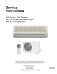
SERVICE MANUAL FLOOR & CEILING SERIES ASF-12A, ASF-18A, ASF-24A, ASF-30A ASF-36, ASF-48A, ASF-60A Contents Part 1 General information………………………………………………….2 Part 2 Indoor units……………………………………………………………5 Part 3 Outdoor units………………………………………………………..36 Part 4 Installation…………………...………………………………………64 Part 5 Control………………………………………………………………..72 Part 1 General Information 1. Model names of units……………………..…………………………………3 2. External Appearance………………………………………………………...3 3. Nomenclature…………………………………………………………………4 4. Features………………………………………………………………………..4 2 1. Model names of units ASF-12A ASF-18A ASF-24A ASF-30A ASF-36A ASF-48A ASF-60A 2. External Appearance 2.1 Indoor units 2.2 Outdoor units 3 3. Nomenclature ASF – 24 A Air Condition Sinclair Refrigerant A R410A Floor & Ceiling Cooling Capacity x 1000 [BTU/h] 4. Features 4.1. New design, more modern and elegant appearance; 4.2. Convenient installation; 4.3. Two direction auto swing (vertical & horizontal) and wide angle air flow; 4.4. Three level fan speed, more humanism design, meets different air-supply requirement; 4.5. Water proof by utilizing the absorbing plastic film on water collector; 4.6. Easy operation. Auto-restart function, remote control and optional wire control method; 4.7. Low noise level plus compact size; 4.8. Universal outdoor design 4 Part 2 Indoor units Ceiling & Floor Type…………………………………………………………6 5 Ceiling & Floor Type 1. Features……………………………………………………………………………………………..7 2. Specification………………………………………………………………………………………..8 3. Dimensions………………………………………………………………………………………..14 4. Service space……………………………………………………………………………………..15 5. Piping diagrams…………………………………………………………………………………..16 6. Wiring diagrams…………………………………………………………………………………..17 7. Capacity Tables…………………………………………………………………………………...20 8. Air Velocity and Temperature Distributions………………………………………………….27 9. Electric Characteristics………………………………………………………………………….29 10. Sound Levels……………………………………………………………………………………...30 11. Exploded view…………………………………………………………………………………….32 6 1. Features 1.1. New design, more modern and elegant appearance. 1.2. Convenient installation -- The ceiling type can be easily installed into a corner of the ceiling even if the ceiling is very narrow -- It is especially useful when installation of an air conditioner in the center of the ceiling is impossible due to a structure such as one lighting 1.3. Two direction auto swing (vertical & horizontal) and wide angle air flow --Air flow directional control minimizes the air resistance and produces wilder air flow to vertical direction. --The range of horizontal air discharge is widened which secures wider air flow distribution to provide more comfortable air circulation no matter where the unit is set up 1.4. Three level fan speed, more humanism design, meets different air-supply requirement. 1.5. Water proof by utilizing the absorbing plastic film on water collector 1.6. Easy operation. Auto-restart function, remote control and optional wire control method. 1.7. Low noise level plus compact size --Shape of the blades has been improved to prevent noise caused by turbulence. 7 2. Specification Cooling & Heating Model ASF-12A ASF-18A ASF-24A Ph-V-Hz 1,220-240V,50Hz 1,220-240V,50Hz 1,220-240V,50Hz Capacity Btu/h 12000 18000 24000 Capacity kW 3.5 5.4 7.1 Input W 1200 1900 2700 Rated current A 6.0 8.5 12.0 Btu/W.h 10.0 9.7 8.9 Capacity Btu/h 13500 20000 26000 Capacity kW 5.9 7.7 Input W 1130 1850 2800 Rated current A 5.0 8.0 12.5 Btu/W.h 12.0 10.9 9.3 Moisture Removal L/h 1.2 1.8 2.4 Max. input consumption W 1500 2400 3300 Max. current A 7.0 11.5 14.5 Starting current A 26 36.8 61 PA140X2C-4FT PA225X2CS-4KU PA290X3CS-4MU1 Type ROTARY ROTARY ROTARY Brand TOSHIBA TOSHIBA TOSHIBA TOSHIBA (Guangdong) TOSHIBA (Guangdong) TOSHIBA (Guangdong) Btu/h 11567 18834 24498 Input W 1145 1870 2430 Rated current(RLA) A 5.3 8.75 11.4 Locked rotor Amp(LRA) A 26 36.8 61 INNER INNER INNER 35/370 μF/V 50/370 μF/V 50/400 μF/V Power supply Cooling Heating EER COP Model Supplier Capacity Thermal protector Capacitor uF 4 RB68AF/T68/Α68tf Compressor Refrigerant oil ml Indoor fan Capacitor motor Speed(hi/lo) ESTER OIL VG74 750 ESTER OIL CG74 950 YSK25-6L YSK55-4L YSK55-4L W 33.4 31.1/29.5 / 115/95/78 115/95/78 uF 1.5uF/450V 2.5uF/450V 2.5uF/450V 1310/ 1190/1040 1310/ 1190/1040 2 3 3 Model Input 480 r/min Number of rows 756/666/592 Tube pitch(a) x row pitch(b) mm 25.4×22 25.4×22 25.4×22 Fin spacing mm 1.8 1.8 1.8 Hydrophilic aluminum Hydrophilic aluminum Hydrophilic aluminum mm Ф9.53 innergroove tube Ф9.53 innergroove tube Ф9.53 innergroove tube mm 804×254×44 804×254×66 804×254×66 3 600/480/400 800/600/500 1000/900/700 Fin type Tube outside dia. and type Indoor coil Coil length x height x width Indoor air flow(Hi/Mid/Lo) m /h 8 dB(A) 43/41/38 43/41/38 45/43/40 Dimension (WxHxD)(body) mm 995×660×198 995×660×198 995×660×198 Packing mm 1089×744×296 1089×744×296 1089×744×296 kg 27/33 27/33 27/33 YDK24-6F YDK53-6K YDK53-6H W 56 130 130 uF 2.5uF/450V 2.5 uF/450V 3μF/450V r/min 800 750 800 2 2 2 Indoor noise level (Hi/Mid/Lo) (WxHxD)(body) Indoor unit Net/Gross weight(body) Model Input Outdoor fan Capacitor motor Speed Number of rows Tube pitch(a)x row pitch(b) mm 21 x13.37 25.4×22 25.4×22 Fin spacing mm 1.5 1.7 1.5 Unhydrophilic aluminum Fin type Tube outside dia. and type mm φ7,Innergroove tube Coil length x height x width mm 651x559x26.7 Outdoor coil Number of circuits Unhydrophilic aluminum Ф9.53,Innergroove tube 775×660×44 Unhydrophilic aluminum Ф9.53,innergroove tube 850×810×44 2 3 4 3 m /h 2100 2400 3000 dB(A) 43 48 55 Dimension(WxHxD) mm 760×590×285 845×695×335 895×860×330 Outdoor Packing (WxHxD) mm 887x655x355 970X770X395 1043X915X395 unit Net/ Gross weight kg 44/48 52/56 68/70 g R410A/1120 R410A/2050 R410A/2600 Design pressure (high side/low side) MPa 4.2/2.5 4.2/2.5 4.2/2.5 Liquid side mm(inch) 6.35 (1/4) 6.35 (1/4) 9.53 (3/8) Gas side mm(inch) 12.7 (1/2) 12.7 (1/2) 16 (5/8) Refrigerant Max. pipe length m 25 25 30 piping m 15 15 15 Operation temp °C 17~30 17~30 17~30 Ambient temp °C -7~45 -7~45 -7~45 Application area m 2 18~26 34~49 40~56 Pieces 63/138/155 49/104/126 44/94/101 Outdoor air flow Outdoor noise level Refrigerant type/Quantity Max. difference in level Qty’per 20’& 40’Fcl 9 Model ASF-30A ASF-36A Ph-V-Hz 1,220-240V,50Hz 3,380V,50Hz Capacity Btu/h 30000 36000 Capacity kW 9.2 10.5 Input W 3750 3750 Rated current A 16.3 6.6 Btu/W.h 8.0 9.6 Capacity Btu/h 32000 39000 Capacity kW 9.4 11.4 Input W 3500 3700 Rated current A 15.2 6.5 Btu/W.h 9.2 10.6 Moisture Removal L/h 3 3.8 Max. input consumption W 4620 4400 Max. current A 21 8.0 Starting current A 97 61 C-SBN301H5D C-SBN303H8D Type SCROLL SCROLL Brand SANYO SANYO Supplier SANYO SANYO(Dalian) Btu/h 33438 33438 Input W 3650 3650 Rated current(RLA) A 17.65 6.58 Locked rotor Amp(LRA) A 97 61 INNER INNER Power supply Cooling EER Heating COP Model Capacity Thermal protector Compressor Capacitor uF 60uF/440V / Refrigerant oil ml FV68S 1700 DAPHNE FV68S 1700 YSK80-4A YSK80-4A Model Indoor motor Input W 142/134/132 142/134/132 fan Capacitor uF 3.5uF/450V 3.5uF/450V r/min 1310/1200/1000 1310/1200/1000 3 3 Speed(hi/lo) Number of rows Tubepitch(a)x row pitch(b) mm 25.4×22 25.4×22 Fin spacing mm 1.7 1.7 Hydrophilic aluminum Hydrophilic aluminum Fin type Tube outside dia.and type mm Ф9.53, inner groove tube Ф9.53, inner groove tube Coil length x height x width mm 905×203×66 905×203×66 Indoor air flow(Hi/Mid/Lo) 3 m /h 1400/1200/1000 1400/1200/1000 Indoor noise level (Hi/Mid/Lo) dB(A) 45/43/40 45/43/40 Dimension (WxHxD)(body) mm 1285×660×198 1285×660×198 Packing mm 1365×744×278 1365×744×278 Indoor coil Indoor unit (WxHxD)(body) 10 Net/Gross weight(body) kg Model Outdoor 34/42 34/42 YDK250-6D YDK250-6D Input W 307 307 fan Capacitor uF 10 uF/450V 10 uF/450V Speed r/min 740 740 2 2 motor Number of rows Tube pitch(a)x row pitch(b) mm 25.4×22 25.4×22 Fin spacing mm 1.7 1.7 unhydrophilic aluminium unhydrophilic aluminum Fin type Outdoor coil Tube outside dia.and type mm Ф9.53, inner groove tube Ф9.53, inner groove tube Coil length x height x width mm 955×915×44 955×915×44 8 8 m /h 3 5000 5000 dB(A) 57 57 Dimension(WxHxD) mm 990×960×360 990×960×360 Packing (WxHxD) mm 1120X1090X435 1120X1090X435 Net/ Gross weight kg 90/102 90/102 g R410A 3450 R410A/3100 MPa 4.2/2.5 4.2/2.5 Liquid side mm(inch) 12.7 (1/2) 12.7 (1/2) Gas side mm(inch) 19 (3/4) 19 (3/4) Number of circuits Outdoor air flow Outdoor noise level Outdoor unit Refrigerant type/Quantity Design pressure (high side/low side) Refrigerant Max. pipe length m 30 30 piping Max. difference in level m 20 20 Operation temp °C 17~30 17~30 Ambient temp °C -7~45 -7~45 2 m 60~85 60~85 Pieces 27/55/62 27/55/62 Application area Qty’per 20’& 40’Fcl 11 Model ASF-48A ASF-60A Ph-V-Hz 3,380V,50Hz 3,380V,50Hz Capacity Btu/h 48000 60,000 Capacity kW 14 17 Input W 4700 6000 Rated current A 8.2 9.8 Btu/W.h 10.2 10.0 Capacity Btu/h 52000 68,000 Capacity kW 15.2 20 Input W 4900 6000 Rated current A 8.6 9.8 Btu/W.h 10.6 11.4 Moisture Removal L/h 4.8 6 Max. input consumption W 5870 7500 Max. current A 10.7 12.8 Starting current A 66 67 Model - C-SBN373H8D C-SBN453H8D Type - SCROLL SCROLL Brand - SANYO SANYO Supplier - SANYO(Dalian) SANYO(Dalian) Capacity Btu/h 48109 55957 Input W 4750 5750 Rated current(RLA) A 8.22 9.77 Locked rotor Amp(LRA) A 66 67 INNER INNER Power supply Cooling EER Heating COP Thermal protector Compressor Capacitor uF / / Refrigerant oil ml DAPHNE FV68S 1700 DAPHNE FV68S 1700 YSK59-4A YSK59-4A Model Indoor motor Input W 118/108/101 118/108/101 fan Capacitor uF 2.5uF/450V 2.5uF/450V r/min 820/695/620 820/695/620 3 3 Speed(hi/lo) Number of rows Tube pitch(a)x row pitch(b) mm 25.4X22 25.4X22 Fin spacing mm 1.7 1.7 Hydrophilic aluminum Hydrophilic aluminum Fin type Tube outside dia. and type mm Ф9.53, inner groove tube Ф9.53, inner groove tube Coil length x height x width mm 1150x254x66 1150x254x66 Indoor air flow(Hi/Mid/Lo) 3 m /h 2000/1800/1600 2000/1800/1600 Indoor noise level (Hi/Mid/Lo) dB(A) 47/45/42 47/45/42 Dimension (WxHxD)(body) mm 1670×680×240 1670×680×240 Packing mm 1764×760×329 1764×760×329 kg 52/62 52/62 Indoor coil Indoor unit (WxHxD)(body) Net/Gross weight(body) 12 Model Outdoor YDK65-6; YDK65-6F YDK65-6F; YDK65-6F Input W 138+156 138+156 fan Capacitor uF 3.5×2 uF/450V 3.5×2 uF/450V Speed r/min 800 800 2 2 motor Number of rows Tube pitch(a)x row pitch(b) mm 25.4×22 25.4×22 Fin spacing mm 1.8 1.8 Hydrophilic aluminum Hydrophilic aluminum Fin type Outdoor coil Tube outside dia. and type mm Ф9.53, inner groove tube Ф9.53, inner groove tube Coil length x height x width mm 715×1220×44 715×1220×44 4 4 Outdoor air flow 3 m /h 6000 6000 Outdoor noise level dB(A) 58 58 Dimension(WxHxD) mm 940×1245×340 940×1245×340 Packing (WxHxD) mm 1058X1380X435 1058X1380X435 Net/ Gross weight kg 112/127 112/127 g R410A/4000 R410A/4200 MPa 4.2/2.5 4.2/2.5 Liquid side mm(inch) 12.7 (1/2) 12.7 (1/2) Gas side mm(inch) 19 (3/4) 19 (3/4) Outdoor unit Number of circuits Refrigerant type/Quantity Design pressure (high side/low side) Refrigerant Max. pipe length m 50 50 piping Max. difference in level m 30 30 Operation temp °C 17~30 17~30 Ambient temp °C -7~45 -7~45 m 80~105 95~120 Pieces 25/50/54 25/50/54 Application area Qty’per 20’& 40’Fcl Notes: 2 1. Nominal cooling capacities are based on the following conditions: Indoor temp: 27°CDB, 19°CWB; Outdoor temp: 35°CDB; 2. Nominal heating capacities are based on the following conditions: Indoor temp: 20°CDB; Outdoor temp: 7°CDB, 6°CWB; 3. Actual noise level may differ, depending on the room structure, etc, since these noise values are from an anechoic room. 13 3. Dimensions 3.1. ASF-12A ASF-18A ASF-24A 995 980 Strengthener 402 4-12Á̌ 18 Overhanging hole Drain point Connecting point of refrigerant pipe Connecting point of refrigerant pipe (Liquid side) (gas side) 3.2. ASF-30A ASF-36A 1285 980 Strengthener 402 4-12Á̌ 18 Overhanging hole Drain point Connecting point of refrigerant pipe Connecting point of refrigerant pipe (Liquid side) (gas side) 3.3. ASF-48A ASF-60A 1610 9 80 240 S trength ener 660 4-1 2× 18 Overh an g ing h ole Dra in point Co nne cti ng po int of refrig eran t pi pe Co nne cti n g po int of refrig eran t pi pe (ga s si de) 14 (Li qui d si de ) 4. Service space >600mm >600mm 15 5. Piping Diagrams Remark: 1. For ASF-12A and ASF-18A, accumulator is not included. 2. For ASF-30A, ASF-36A and ASF-48A, check valve and auxiliary capillary is not included. 16 6. Wiring Diagrams 6.1 ASF-12A DI S P L AY BOARD XP1 XS1 I N DOOR WI RI NG DIAGRAM CN12 CN13 ( WHI TE) ( RED) CN10 CODE CN15 RL8 CN3 CN1 CN2 CN16 XS1~4 T4 XP3 XS3 Y/ G FAN1 WHITE I NDOOR FAN C AP CN1-CN24 P.C.BOARD SOCKETS T4 TRANSFORMER FAN1 I N DOOR FAN CONNECTORS XP1~4 MAIN CONTROL BOARD CN5 PART NAME CAP1 WHITE CONNECTORS RT1 ROOMTEMP. SENSOR RT2 PIPE TEMP. SENSOR XT1 XT2 6- WAY TERMI NAL 5- WAY T ERMI N AL KM1 RELAY FOR COMPRESSOR GM 1 LEVEL SWING MOTOR GM 2 PLUMB SWING MOTOR BLACK( C) BLUE( N) RED BLACK BLACK RED WHITE XT1 L N 1 2(N) Y/ G BLACK( E) 3 4 5 WHITE( T3) XT2 BLACK( HI) RED( LO) BLACK( L) KM 1 BLUE ( S. V) CAP1 Y/ G POWER TO OUTDOOR UNIT TO OUTDOOR UNIT 6.2 ASF-18A D I SPLAY BOARD XP1 XS1 I NDOOR WIRING DIAGRAM CN12 ( WHI TE) C N 10 CN13 ( RED) CODE CN15 CN3 CN1 C N2 CN16 T4 XP3 XS3 Y/ G FAN1 WHITE I NDOOR FANCAP CN1-CN24 P. C.BOARD SOCKETS MAIN CONTROL BOARD CN5 PART NAME CAP1 RL8 T4 FAN1 XP1 ~4 XS1~4 CONNECTORS RT1 ROOM TEMP.SENSOR RT2 PIPE TEMP.SENSOR XT1 XT2 5 - WAY TERMINAL TRANSFORMER INDOOR FAN CONNECTORS 6 - WAY TERMINAL RELAY FOR COMPRESSOR KM1 WHITE GM1 LEVEL SWING MOTOR GM2 PLUMB SWING MOTOR BLACK( C) BLUE( N) RED BLACK RED BLACK WHITE XT1 L WHITE( T3) 3 4 5 BLACK(E) XT2 BLACK( HI ) RED( LO) BLACK( L) KM1 BLUE( S. V) CAP1 TO OUTDOOR UNIT N 1 2 (N) Y/ G Y/ G TO OUTDOOR UNIT POWER 17 6.3 ASF-24A 6.1.4. ASF-30A 18 6.1.5. ASF-36A 6.1.6. ASF-48A ASF-60A 19 7. Capacity Tables Model: ASF-12A Cooling OUTDOOR TEMPERATURE DRY Indoor 21ºC 25ºC 30ºC 35ºC 40ºC 45ºC 50ºC Total capacity kW 3.38 3.23 3.12 2.94 2.82 2.73 2.65 Sensitive capacity kW 2.70 2.59 2.49 2.35 2.26 2.19 2.12 Input kW. 0.76 0.86 0.97 1.08 1.19 1.30 1.40 Total capacity kW 3.70 3.54 3.41 3.22 3.09 2.99 2.90 Sensitive capacity kW 2.96 2.83 2.73 2.58 2.47 2.40 2.32 Input kW. 0.80 0.91 1.03 1.14 1.25 1.37 1.48 Total capacity kW 4.03 3.85 3.71 3.50 3.36 3.26 3.15 Sensitive capacity kW 3.22 3.08 2.97 2.80 2.69 2.60 2.52 Input kW. 0.84 0.96 1.08 1.20 1.32 1.44 1.56 Total capacity kW 4.63 4.43 4.27 4.03 3.86 3.74 3.62 Sensitive capacity kW 3.70 3.54 3.41 3.22 3.09 2.99 2.90 Input kW. 0.97 1.10 1.24 1.38 1.52 1.66 1.79 Conditions 21ºC D 15ºC W 24ºC D 17ºC W 27ºC D 19ºC W 32ºC D 23ºC W Heating OUTDOOR CONDITIONS Indoor 24ºC D 12ºC D 7ºC D 4ºC D 0ºC D -5ºC D -7ºC D -15ºC D Conditions 18ºC W 11ºC W 6ºC W 3ºC W -1ºC W -6ºC W -8ºC W -16ºC W Capacity kW 6.56 5.24 4.37 3.93 3.71 3.28 3.06 2.84 Input kW. 1.95 1.56 1.30 1.23 1.17 1.10 1.04 0.91 Capacity kW 6.16 4.92 4.10 3.69 3.49 3.08 2.87 2.67 Input kW. 1.83 1.46 1.22 1.16 1.10 1.04 0.98 0.85 Capacity kW 5.70 4.56 3.80 3.42 3.23 2.85 2.66 2.47 Input kW. 1.70 1.36 1.13 1.07 1.02 0.96 0.90 0.79 Capacity kW 5.24 4.20 3.50 3.15 2.97 2.62 2.45 2.27 Input kW. 1.56 1.25 1.04 0.99 0.94 0.88 0.83 0.73 Capacity kW 4.56 3.65 3.04 2.74 2.58 2.28 2.13 1.98 Input kW. 1.36 1.08 0.90 0.86 0.81 0.77 0.72 0.63 15ºC 18ºC 20ºC 22ºC 27ºC 20 Model: ASF-18A Cooling OUTDOOR TEMPERATURE DRY Indoor 21ºC 25ºC 30ºC 35ºC 40ºC 45ºC 50ºC Total capacity kW 5.22 4.99 4.81 4.54 4.35 4.22 4.08 Sensitive capacity kW 4.17 3.99 3.85 3.63 3.48 3.37 3.27 Input kW. 1.20 1.37 1.54 1.71 1.88 2.05 2.22 Total capacity kW 5.71 5.46 5.27 4.97 4.77 4.62 4.47 Sensitive capacity kW 4.57 4.37 4.21 3.97 3.82 3.70 3.58 Input kW. 1.26 1.44 1.62 1.81 1.99 2.17 2.35 Total capacity kW 6.21 5.94 5.72 5.40 5.18 5.02 4.86 Sensitive capacity kW 4.97 4.75 4.58 4.32 4.15 4.02 3.89 Input kW. 1.33 1.52 1.71 1.90 2.09 2.28 2.47 Total capacity kW 7.14 6.83 6.58 6.21 5.96 5.78 5.59 Sensitive capacity kW 5.71 5.46 5.27 4.97 4.77 4.62 4.47 Input kW. 1.53 1.75 1.97 2.19 2.40 2.62 2.84 Conditions 21ºC D 15ºC W 24ºC D 17ºC W 27ºC D 19ºC W 32ºC D 23ºC W Heating OUTDOOR CONDITIONS Indoor 24ºC D 12ºC D 7ºC D 4ºC D 0ºC D -5ºC D -7ºC D -15ºC D Conditions 18ºC W 11ºC W 6ºC W 3ºC W -1ºC W -6ºC W -8ºC W -16ºC W Capacity kW 10.35 8.28 6.90 6.21 5.87 5.18 4.83 4.49 Input kW. 3.19 2.55 2.13 2.02 1.91 1.81 1.70 1.49 Capacity kW 9.72 7.78 6.48 5.83 5.51 4.86 4.54 4.21 Input kW. 3.00 2.40 2.00 1.90 1.80 1.70 1.60 1.40 Capacity kW 9.00 7.20 6.00 5.40 5.10 4.50 4.20 3.90 Input kW. 2.78 2.22 1.85 1.76 1.67 1.57 1.48 1.30 Capacity kW 8.28 6.62 5.52 4.97 4.69 4.14 3.86 3.59 Input kW. 2.55 2.04 1.70 1.62 1.53 1.45 1.36 1.19 Capacity kW 7.20 5.76 4.80 4.32 4.08 3.60 3.36 3.12 Input kW. 2.22 1.78 1.48 1.41 1.33 1.26 1.18 1.04 15ºC 18ºC 20ºC 22ºC 27ºC 21 Model: ASF-24A Cooling OUTDOOR TEMPERATURE DRY Indoor 21ºC 25ºC 30ºC 35ºC 40ºC 45ºC 50ºC Total capacity kW 6.86 6.56 6.32 5.96 5.73 5.55 5.37 Sensitive capacity kW 5.49 5.25 5.06 4.77 4.58 4.44 4.29 Input kW. 1.70 1.94 2.19 2.43 2.67 2.92 3.16 Total capacity kW 7.51 7.19 6.92 6.53 6.27 6.07 5.88 Sensitive capacity kW 6.01 5.75 5.54 5.23 5.02 4.86 4.70 Input kW. 1.80 2.05 2.31 2.57 2.82 3.08 3.33 Total capacity kW 8.17 7.81 7.53 7.10 6.82 6.60 6.39 Sensitive capacity kW 6.53 6.25 6.02 5.68 5.45 5.28 5.11 Input kW. 1.89 2.16 2.43 2.70 2.97 3.24 3.51 Total capacity kW 9.39 8.98 8.65 8.17 7.84 7.59 7.35 Sensitive capacity kW 7.51 7.19 6.92 6.53 6.27 6.07 5.88 Input kW. 2.17 2.48 2.79 3.11 3.42 3.73 4.04 Conditions 21ºC D 15ºC W 24ºC D 17ºC W 27ºC D 19ºC W 32ºC D 23ºC W Heating OUTDOOR CONDITIONS Indoor 24ºC D 12ºC D 7ºC D 4ºC D 0ºC D -5ºC D -7ºC D -15ºC D Conditions 18ºC W 11ºC W 6ºC W 3ºC W -1ºC W -6ºC W -8ºC W -16ºC W Capacity kW 13.80 11.04 9.20 8.28 7.82 6.90 6.44 5.98 Input kW. 4.83 3.86 3.22 3.06 2.90 2.74 2.58 2.25 Capacity kW 12.96 10.37 8.64 7.78 7.34 6.48 6.05 5.62 Input kW. 4.54 3.63 3.02 2.87 2.72 2.57 2.42 2.12 Capacity kW 12.00 9.60 8.00 7.20 6.80 6.00 5.60 5.20 Input kW. 4.20 3.36 2.80 2.66 2.52 2.38 2.24 1.96 Capacity kW 11.04 8.83 7.36 6.62 6.26 5.52 5.15 4.78 Input kW. 3.86 3.09 2.58 2.45 2.32 2.19 2.06 1.80 Capacity kW 9.60 7.68 6.40 5.76 5.44 4.80 4.48 4.16 Input kW. 3.36 2.69 2.24 2.13 2.02 1.90 1.79 1.57 15ºC 18ºC 20ºC 22ºC 27ºC 22 Model: ASF-30A Cooling OUTDOOR TEMPERATURE DRY Indoor 21ºC 25ºC 30ºC 35ºC 40ºC 45ºC 50ºC Total capacity kW 8.89 8.50 8.19 7.73 7.42 7.19 6.96 Sensitive capacity kW 7.11 6.80 6.55 6.18 5.94 5.75 5.56 Input kW. 2.36 2.70 3.04 3.38 3.71 4.05 4.39 Total capacity kW 9.73 9.31 8.97 8.46 8.13 7.87 7.62 Sensitive capacity kW 7.79 7.45 7.18 6.77 6.50 6.30 6.09 Input kW. 2.49 2.85 3.21 3.56 3.92 4.28 4.63 Total capacity kW 10.58 10.12 9.75 9.20 8.83 8.56 8.28 Sensitive capacity kW 8.46 8.10 7.80 7.36 7.07 6.84 6.62 Input kW. 2.63 3.00 3.38 3.75 4.13 4.50 4.88 Total capacity kW 12.17 11.64 11.21 10.58 10.16 9.84 9.52 Sensitive capacity kW 9.73 9.31 8.97 8.46 8.13 7.87 7.62 Input kW. 3.02 3.45 3.88 4.31 4.74 5.18 5.61 Conditions 21ºC D 15ºC W 24ºC D 17ºC W 27ºC D 19ºC W 32ºC D 23ºC W Indoor 24ºC D 12ºC D 7ºC D 4ºC D 0ºC D -5ºC D -7ºC D -15ºC D Conditions 18ºC W 11ºC W 6ºC W 3ºC W -1ºC W -6ºC W -8ºC W -16ºC W Capacity kW 16.22 12.97 10.81 9.73 9.19 8.11 7.57 7.03 Input kW. 6.04 4.83 4.03 3.82 3.62 3.42 3.22 2.82 Capacity kW 15.23 12.18 10.15 9.14 8.63 7.61 7.11 6.60 Input kW. 5.67 4.54 3.78 3.59 3.40 3.21 3.02 2.65 Capacity kW 14.10 11.28 9.40 8.46 7.99 7.05 6.58 6.11 Input kW. 5.25 4.20 3.50 3.33 3.15 2.98 2.80 2.45 Capacity kW 12.97 10.38 8.65 7.78 7.35 6.49 6.05 5.62 Input kW. 4.83 3.86 3.22 3.06 2.90 2.74 2.58 2.25 Capacity kW 11.28 9.02 7.52 6.77 6.39 5.64 5.26 4.89 Input kW. 4.20 3.36 2.80 2.66 2.52 2.38 2.24 1.96 15ºC 18ºC 20ºC 22ºC 27ºC 23 Model: ASF-36A Cooling OUTDOOR TEMPERATURE DRY Indoor 21ºC 25ºC 30ºC 35ºC 40ºC 45ºC 50ºC 10.14 9.70 9.35 8.82 8.47 8.20 7.94 Sensitive capacity kW 8.11 7.76 7.48 7.06 6.77 6.56 6.35 Input kW. 2.36 2.70 3.04 3.38 3.71 4.05 4.39 Total capacity kW 11.11 10.63 10.24 9.66 9.27 8.98 8.69 Sensitive capacity kW 8.89 8.50 8.19 7.73 7.42 7.19 6.96 Input kW. 2.49 2.85 3.21 3.56 3.92 4.28 4.63 Total capacity kW 12.08 11.55 11.13 10.50 10.08 9.77 9.45 Sensitive capacity kW 9.66 9.24 8.90 8.40 8.06 7.81 7.56 Input kW. 2.63 3.00 3.38 3.75 4.13 4.50 4.88 Total capacity kW 13.89 13.28 12.80 12.08 11.59 11.23 10.87 Sensitive capacity kW 11.11 10.63 10.24 9.66 9.27 8.98 8.69 Input kW. 3.02 3.45 3.88 4.31 4.74 5.18 5.61 Conditions Total capacity kW 21ºC D 15ºC W 24ºC D 17ºC W 27ºC D 19ºC W 32ºC D 23ºC W Heating OUTDOOR CONDITIONS Indoor 24ºC D 12ºC D 7ºC D 4ºC D 0ºC D -5ºC D -7ºC D -15ºC D Conditions 18ºC W 11ºC W 6ºC W 3ºC W -1ºC W -6ºC W -8ºC W -16ºC W Capacity kW 19.67 15.73 13.11 11.80 11.14 9.83 9.18 8.52 Input kW. 6.38 5.11 4.26 4.04 3.83 3.62 3.40 2.98 Capacity kW 18.47 14.77 12.31 11.08 10.47 9.23 8.62 8.00 Input kW. 5.99 4.80 4.00 3.80 3.60 3.40 3.20 2.80 Capacity kW 17.10 13.68 11.40 10.26 9.69 8.55 7.98 7.41 Input kW. 5.55 4.44 3.70 3.52 3.33 3.15 2.96 2.59 Capacity kW 15.73 12.59 10.49 9.44 8.91 7.87 7.34 6.82 5.11 4.08 3.40 3.23 3.06 2.89 2.72 2.38 Capacity kW 13.68 10.94 9.12 8.21 7.75 6.84 6.38 5.93 Input kW. 4.44 3.55 2.96 2.81 2.66 2.52 2.37 2.07 15ºC 18ºC 20ºC 22ºC 27ºC Input kW. 24 Model: ASF-48A Cooling OUTDOOR TEMPERATURE DRY Indoor 21ºC 25ºC 30ºC 35ºC 40ºC 45ºC 50ºC Total capacity kW 13.52 12.94 12.47 11.76 11.29 10.94 10.58 Sensitive capacity kW 10.82 10.35 9.97 9.41 9.03 8.75 8.47 Input kW. 2.96 3.38 3.81 4.23 4.65 5.08 5.50 Total capacity kW 14.81 14.17 13.65 12.88 12.36 11.98 11.59 Sensitive capacity kW 11.85 11.33 10.92 10.30 9.89 9.58 9.27 Input kW. 3.13 3.57 4.02 4.47 4.91 5.36 5.80 Total capacity kW 16.10 15.40 14.84 14.00 13.44 13.02 12.60 Sensitive capacity kW 12.88 12.32 11.87 11.20 10.75 10.42 10.08 Input kW. 3.29 3.76 4.23 4.70 5.17 5.64 6.11 Total capacity kW 18.52 17.71 17.07 16.10 15.46 14.97 14.49 Sensitive capacity kW 14.81 14.17 13.65 12.88 12.36 11.98 11.59 Input kW. 3.78 4.32 4.86 5.41 5.95 6.49 7.03 Conditions 21ºC D 15ºC W 24ºC D 17ºC W 27ºC D 19ºC W 32ºC D 23ºC W Heating OUTDOOR CONDITIONS Indoor 24ºC D 12ºC D 7ºC D 4ºC D 0ºC D -5ºC D -7ºC D -15ºC D Conditions 18ºC W 11ºC W 6ºC W 3ºC W -1ºC W -6ºC W -8ºC W -16ºC W Capacity kW 26.22 20.98 17.48 15.73 14.86 13.11 12.24 11.36 Input kW. 8.45 6.76 5.64 5.35 5.07 4.79 4.51 3.94 Capacity kW 24.62 19.70 16.42 14.77 13.95 12.31 11.49 10.67 Input kW. 7.94 6.35 5.29 5.03 4.76 4.50 4.23 3.70 Capacity kW 22.80 18.24 15.20 13.68 12.92 11.40 10.64 9.88 Input kW. 7.35 5.88 4.90 4.66 4.41 4.17 3.92 3.43 Capacity kW 20.98 16.78 13.98 12.59 11.89 10.49 9.79 9.09 Input kW. 6.76 5.41 4.51 4.28 4.06 3.83 3.61 3.16 Capacity kW 18.24 14.59 12.16 10.94 10.34 9.12 8.51 7.90 Input kW. 5.88 4.70 3.92 3.72 3.53 3.33 3.14 2.74 15ºC 18ºC 20ºC 22ºC 27ºC 25 Model: ASF-60A Cooling OUTDOOR TEMPERATURE DRY Indoor 21ºC 25ºC 30ºC 35ºC 40ºC 45ºC 50ºC Total capacity kW 16.42 15.71 15.14 14.28 13.71 13.28 12.85 Sensitive capacity kW 13.14 12.57 12.11 11.42 10.97 10.62 10.28 Input kW. 3.78 4.32 4.86 5.40 5.94 6.48 7.02 Total capacity kW 17.99 17.20 16.58 15.64 15.01 14.55 14.08 Sensitive capacity kW 14.39 13.76 13.26 12.51 12.01 11.64 11.26 Input kW. 3.99 4.56 5.13 5.70 6.27 6.84 7.41 Total capacity kW 19.55 18.70 18.02 17.00 16.32 15.81 15.30 Sensitive capacity kW 15.64 14.96 14.42 13.60 13.06 12.65 12.24 Input kW. 4.20 4.80 5.40 6.00 6.60 7.20 7.80 Total capacity kW 22.48 21.51 20.72 19.55 18.77 18.18 17.60 Sensitive capacity kW 17.99 17.20 16.58 15.64 15.01 14.55 14.08 Input kW. 4.83 5.52 6.21 6.90 7.59 8.28 8.97 Conditions 21ºC D 15ºC W 24ºC D 17ºC W 27ºC D 19ºC W 32ºC D 23ºC W Indoor 24ºC D 12ºC D 7ºC D 4ºC D 0ºC D -5ºC D -7ºC D -15ºC D Conditions 18ºC W 11ºC W 6ºC W 3ºC W -1ºC W -6ºC W -8ºC W -16ºC W Capacity kW 34.50 27.60 23.00 20.70 19.55 17.25 16.10 14.95 Input kW. 10.35 8.28 6.90 6.56 6.21 5.87 5.52 4.83 Capacity kW 32.40 25.92 21.60 19.44 18.36 16.20 15.12 14.04 Input kW. 9.72 7.78 6.48 6.16 5.83 5.51 5.18 4.54 Capacity kW 30.00 24.00 20.00 18.00 17.00 15.00 14.00 13.00 Input kW. 9.00 7.20 6.00 5.70 5.40 5.10 4.80 4.20 Capacity kW 27.60 22.08 18.40 16.56 15.64 13.80 12.88 11.96 Input kW. 8.28 6.62 5.52 5.24 4.97 4.69 4.42 3.86 Capacity kW 24.00 19.20 16.00 14.40 13.60 12.00 11.20 10.40 Input kW. 7.20 5.76 4.80 4.56 4.32 4.08 3.84 3.36 15ºC 18ºC 20ºC 22ºC 27ºC 26 8. Air Velocity and Temperature Distributions Discharge angle 60° (CEILING) Airflow velocity Temperature 27 Discharge angle 60°(FLOOR) Airflow velocity Temperature 28 9. Electric Characteristics Power supply Model Indoor fan motor Hz Voltage Power output FLA ASF-12A 50 220~240 25 0.13 ASF-18A 50 220~240 55 0.355 ASF-24A 50 220~240 55 0.355 ASF-30A 50 220~240 80 0.475 ASF-36A 50 380 80 0.475 ASF-48A 50 380 59 0.34 ASF-60A 50 380 59 0.34 Symbols: FLA: Full Load Amps. 29 10. Sound Levels Ceiling Floor High airflow Low airflow Sound pressure level dBŁ 0̈dB=0.0002¦ ĚbarŁ © Sound pressure level dBŁ 0̈dB=0.0002¦ ĚbarŁ © 12000 BTU/h 18000 BTU/h Audibility limits of continuous white sound Audibility limits of continuous white sound Octave band center frequencyŁ ḦzŁ © Octave band center frequencyŁ ḦzŁ © Ceiling Floor 30 Sound pressure level dBŁ 0̈dB=0.0002¦ ĚbarŁ © Sound pressure level dBŁ 0̈dB=0.0002¦ ĚbarŁ © 24000 BTU/h 30000 BTU/h 36000 BTU/h A udibility lim its of continuous w hite sound Audibility limits of continuous white sound O ctave band center frequency Ł Ḧ z Ł © Octave band center frequency Ł Ḧz Ł © Ceiling Floor Sound pressure level dBŁ 0̈dB=0.0002¦ ĚbarŁ © Sound pressure level dBŁ 0̈dB=0.0002¦ ĚbarŁ © 48000 BTU/h 60000 BTU/h Audibility limits of continuous white sound Audibility limits of continuous white sound Octave band center frequencyŁ ḦzŁ © Octave band center frequencyŁ ḦzŁ © Ceiling Floor 31 11. Exploded view 11.1 ASF-12A No. ASF-18A ASF-24A Part Name Quantity No. Part Name Quantity 1 Air inlet grille 1 20 Installation clamp 2 2 filter 2 21 Right holder,eva 1 3 Electric control assy 1 22 Base pan 1 3.1 Electric part box 1 23 Evaporator 1 3.2 Wire joint 1 23.1 Electric expansive valve 1 3.3 Wire joint ROHS 1 23.2 Electric Expansion loop 1 3.4 Pipe Temperature Sensor Ass'y II 1 24 left holder, eva 1 3.5 Pipe Temperature Sensor Ass'y 1 25 left fixed board, eva 1 3.6 Transformer 1 26 left frame holder, eva 1 3.7 Main control PCB 1 27 left clapboard 1 3.8 Fan motor capacitor 1 28 right installation board 1 4 Cover for E-box 1 29 right clapboard 1 5 Panel Ass'y 1 30 middle beam 1 6 Display panel box 1 31 grille lock 1 7 Display PCB assy 1 32 fan motor 1 8 Manual button 1 33 grille strip 2 9 Sealing foam I for air out frame 1 34 grille strip screw 2 10 Sealing foam II for air out frame 2 35 Sroll-shell, down 2 11 Sealing foam III for air out frame 1 36 Sroll-shell, up 2 32 12 Air-out frame assy 1 37 fan 2 13 Back clapboard 1 38 left fixing clamp for motor 1 14 wiry holder for water collector 1 39 right fixing clamp for motor 1 15 Collect water pan assy 1 40 Strenghten board for motor 1 16 plastic cover 1 41 left installation board 1 17 base pan frame assy 1 42 holder 1 18 Right frame holder, eva 1 43 Remote Controller 1 19 Right fixed board, eva 1 11.2 ASF-30A ASF-36A 33 No. Part Name Quantity No. Part Name Quantity 1 Air inlet grille 1 21 Right holder,eva 1 2 filter 3 22 Base pan 1 3 E-Parts box ass'y 1 23 Evaporator 1 3.1 Electric part box 1 24 left holder, eva 1 3.2 Wire joint 1 25 left fixed board, eva 1 3.3 Wire joint 1 26 left frame holder, eva 1 3.4 Pipe temp. sensor ass'y 1 27 left clapboard 1 3.5 Room temp. sensor ass'y 1 28 right installation board 1 3.6 Transformer 1 29 right clapboard 1 3.7 Main control PCB 1 30 middle beam 1 3.8 Fan motor capacitor 1 31 grille lock 2 4 Cover for E-box 1 32 fan motor 1 5 Panel ass'y 1 33 grille strip 2 6 Display panel box 1 34 grille strip screw 2 7 Display board ass'y 1 35 Sroll-shell, down 3 8 Manual button 1 36 Sroll-shell, up 3 9 Sealing foam I for air out frame 1 37 fan 3 10 Sealing foam II for air out frame 3 38 left fixing clamp for motor 1 11 Sealing foam III for air out frame 1 39 right fixing clamp for motor 1 12 Air-out frame assy 1 40 Strenghten board for motor 1 13 Back clapboard 1 41 left installation board 1 14 wiry holder for water collector 1 42 Supporting board for bearing 1 15 Collect water pan assy 1 43 bearing underlay 1 16 plastic cover 1 44 Axis 1 17 base pan frame assy 1 45 Fixing board for bearing 1 18 Right frame holder, eva 1 46 Coupling 1 19 Right fixed board, eva 1 47 holder 1 20 Installation clamp 2 48 Remote Controller 1 34 11.3 ASF-48A No. ASF-60A Part Name Quantity No. Part Name Quantity 1 Air inlet grille 2 23 left sealing board 1 2 filter 4 24 left clapboard 1 3 left fixing clamp for motor 2 25 E-Parts box ass'y 1 4 right fixing clamp for motor 2 25.1 Wire joint 1 5 Strenghten board for motor 2 25.2 Wire joint 1 6 E-part box underlay 1 25.3 Pipe temp. sensor ass'y 1 7 Sroll-shell, down 4 25.4 Room temp. sensor ass'y 1 8 Sroll-shell, up 4 25.5 Transformer 1 9 fan 2 25.6 Main control PCB 1 10 fan motor 2 25.7 Fan motor capacitor 2 11 fan motor holder 2 25.8 Electric part box 1 12 right holder, filter 2 26 Cover for E-box 1 13 left holder, filter 2 27 Collect water pan ass'y 1 14 middle beam 1 28 cover 1 15 pipe fixed board 1 29 Display board ass'y 1 16 Sealing foam for collect pan 2 30 Display panel box 1 17 Installation clamp 2 31 Sealing foam I for air out frame 2 18 right clapboard 1 32 Air-out frame assy 1 19 right sealing board 1 33 Evaporator 1 20 right installation board 1 34 plastic cover 1 21 Base pan ass'y 1 35 holder 1 22 left installation board 1 36 Remote Controller 1 35 Part 3 Outdoor Units Outdoor Units………………………………………………………………..37 36 Outdoor Units 1. Dimensions……………………………………………………………………………………..38 2. Service Space…………………………………………………………………………………..41 3. Wiring Diagrams……………………………………………………………………………….42 4. Field Wiring……………………………………………………………………………………..45 5. Electric Characteristics………………………………………………………………………46 6. Operation Limits……………………………………………………………………………….46 7. Sound Levels…………………………………………………………………………………..47 8. Exploded view………………………………………………………………………………….49 9. Troubleshooting……………………………………………………………………………….56 37 1. Dimensions 1.1 ASF-12A 750 590 285 290 315 62 110 530 12. 5 1.2. ASF-18A 38 1.3. ASF-24A 895 860 330 62 141 590 1.4. ASF-30A ASF-36A 39 1.5. ASF-48A ASF-60A 40 2. Service Space Capacity ≤ 60000 Btu/h Obstacle >30cm Air inlet >30cm >60cm (Wall or obstacle) Air inlet Fix with bolt Maintain channel >200cm >60cm Air outlet Deep foundation Necessary width 600mm M10 bolt 4pieces per unit 41 3. Wiring diagrams 3.1 Cooling & Heating 3.1.1. ASF-12A 3.1.2. ASF-18A 42 3.1.3. ASF-24A 3.1.4. ASF-30A 43 3.1.5. ASF-36A 3.1.6. ASF-48A, ASF-60A 44 4. Field Wiring 45 5. Electric Characteristics Power supply Model Compressor Outdoor fan motor Power Hz Voltage RLA MSC ASF-12A 50 220~240 5.3 26 24 0.27 ASF-18A 50 220~240 8.75 36.8 53 0.61 ASF-24A 50 220~240 11.4 61 53 0.66 ASF-30A 50 220~240 17.65 97 250 1.38 ASF-36A 50 380 6.58 61 250 1.38 ASF-48A 50 380 8.22 66 65 0.7 ASF-60A 50 380 9.77 67 65 0.7 Symbols: MSC: Max. Starting Current RLA: Rated Locked Current FLA: Full Load Amps. 6. Operation Limits Ensure the operating temperature is in allowable range. 46 output FLA 7. Sound levels 1m Microphone 12000 Btu/h 18000 Btu/h 47 24000 Btu/h 30000 Btu/h & 36000 Btu/h 48000 Btu/h & 60000 Btu/h 48 8. Exploded view Cooling & Heating 8.1 ASF-12A No. Part Name Quantity No. Part Name Quantity 1 Clamp for front net 6 15 Capacitor clamp 1 2 Front net 1 16 Wire joint,5p 1 3 Front clapboard 1 Wire joint, 2p 1 4 Propeller fan 1 17 Left supporter 1 5 Fan motor 1 18 Separating board 1 6 Holder for fan motor 1 19 Condenser 1 7 Chassis 1 20 Water collector 1 8 Compressor 1 21 Right clapboard 1 9 Installation plate for valves 1 22 Big handle 1 10 Gas pipe valve 1 23 Cover 1 4-way valve 1 24 Small handle 1 11 Liquid pipe valve 1 25 Rear net 1 12 Fan motor capacitor 1 26 Copper nut, TLM-C03 1 13 Installation board for E-parts 1 27 Copper nut, TLM-A01 1 14 Compressor capacitor 1 28 Pipe temp sensor ass'y 1 49 8.2 ASF-18A No. Part Name Quantity No. Part Name Quantity 1 Clamp for front net 8 19 Wire joint 1 2 Front net 1 20 Separating board 1 3 Front clapboard 1 21 Installation board for E-parts 1 4 Propeller fan 1 22 Washer for wire joint 1 5 Fan motor 1 23 Clamp for wiring 1 6 Holder for fan motor 1 24 Compressor capacitor 1 7 Foam over holder for motor 1 25 Capacitor clamp 1 8 Cover 1 26 Chassis 1 9 Little handle 1 27 Front right clapboard 1 10 Condenser 1 28 Compressor 1 11 Support board for motor holder 1 29 Liquid valve assy 1 12 Left clapboard 1 30 Liquid pipe valve 1 13 Rear net 1 31 4-Ways valve assy 1 14 Rear right clapboard 1 Gas pipe valve 1 15 Big handle 1 Four-way Valve 1 16 Installation plate for valves 1 33 Copper nut, TLM-A01 1 17 Water collector 1 34 Copper nut, TLM-C03 1 18 Fan motor capacitor 1 32 50 8.3 ASF-24A No. Part Name Quantity No. Part Name Quantity 1 Front net 1 20 AC contactor 1 2 Cabinet,Front 1 21 Capacitor,Fan Motor 1 3 Fan,Propeller 1 22 Wire 1 4 Fan Motor 1 5 Mount,Fan Motor 1 6 Topcap Ass'y 1 24 Compressor 1 7 Condenser Ass'y 1 25 Fixture,Segregator 1 8 Inlet Pipe for Condenser 1 4-way Valve 1 9 Outlet Pipe for Condenser 1 4-way Valve Solenoid 1 10 Rear Net 1 27 Liquid pipe valve 1 11 Support board,Back side 1 28 Capillary pipe 1 12 Handle 2 29 Gas pipe valve 1 13 Separating board 1 30 refrigerant Container 1 14 Base Pan Ass'y 1 31 Pipe temp. sensor assy 1 15 Cabinet,Front-Right 1 32 Support board, Left Side 1 16 Capacitor Clamp 1 33 Big handle 1 17 Capacitor, Compressor 1 34 Filter 1 Wiring Installation Panel 1 35 Small Handle 1 Washer for wire joint 1 36 Copper nut, TLM-B02 1 Terminal install board 1 37 Copper nut, TLM-D04 1 Terminal Block,2p 1 18 19 23 26 Clamp Terminal Block,5p 1 Terminal Block,2p 1 51 8.4 ASF-30S No. Part Name Quantity No. Part Name Quantity 1 Clamp for front net 10 20 Fan motor capacitor 1 2 Front net 1 21 Installation board for E-parts 1 3 Front clapboard 1 22 AC contactor 1 4 Propeller fan 1 23 Main control box 1 5 Fan motor 1 24 Wire joint for multiplexer 2 6 Holder for fan motor 1 25 Wire joint for multiplexer 1 7 Chassis 1 26 Washer for wire joint 1 8 Separating board 1 27 Wire clamp 1 9 Cover 1 28 Wire joint for power 1 Condenser I 1 29 Liquid valve assy 1 Condenser II 1 30 Liquid valve 1 11 Support board for motor holder 1 31 4-way valve assy 1 12 Left supporting bar 1 32 4-way Valve 1 13 Rear net 1 33 Gas valve 1 14 Rear right clapboard 1 34 Compressor 1 15 Big handle 1 35 Discharge temp sensor 1 16 Installation plate for valves 1 36 Front right clapboard 1 17 Pipe temp sensor 1 37 Copper nut, TLM-C03 1 18 Refrigerant container 1 38 Copper nut, TLM-E05 1 19 Container clamp 1 10 52 8.5 ASF-36A No. Part Name Quantity No. Part Name Quantity 1 Clamp for front net 10 20 Fan motor capacitor 1 2 Front net 2 21 Installation board for E-parts 1 3 Front clapboard 1 22 AC contactor 1 4 Propeller fan 1 23 Main control board,Outdoor unit 1 5 Fan motor 1 24 Wire joint for multiplexer 2 6 Holder for fan motor 1 25 Wire joint for multiplexer 1 7 Chassis 1 26 Washer for wire joint 1 8 Separating board 1 27 Wire clamp 1 9 Cover 1 28 Wire joint for power 1 Condenser I 1 29 Liquid valve assy 1 Condenser II 1 30 Liquid valve 1 11 Support board for motor holder 1 31 4-way valve assy 1 12 Left supporting bar 1 32 4-way valve 1 13 Rear net 1 33 Gas valve 1 14 Rear right clapboard 1 34 Compressor 1 15 Big handle 1 35 Discharge temp sensor 1 16 Installation plate for valves 1 36 Front right clapboard 1 17 Pipe temp sensor 1 37 Copper nut, TLM-C03 1 18 Refrigerant container 1 38 Copper nut, TLM-E05 1 19 Container clamp 1 10 53 8.6 ASF-48A No. Part Name Quantity No. Part Name Quantity 1 Front net 2 17 Capacitor,Fan Motor 2 2 Cabinet,Front 1 18 Terminal 3 3 Fan,Propeller 2 19 AC contactor 1 4 Fan Motor 2 20 Low Pressure Valve 1 5 Room temp. sensor,outdoor 1 21 PCB board,outdoor unit 1 6 Mount,Fan Motor 1 22 Terminal 1 7 Topcap 1 23 Wire joint for power 1 Condensator I 1 24 Compressor 1 Condensator II 1 25 Refrigerator Container 1 9 Left Side Cabinet 1 26 Fixture,Segregator 1 10 Supporter, Rear Cabinet 1 Four-way Valve 1 10 Supporter, Rear Cabinet 1 Four-way Valve Solenoid 1 11 Cabinet,Back side 1 28 Low Pressure Valve 1 12 Handle 2 29 Capillary 1 13 Plate,Sound-proof 1 30 Electric heat belt for comp 1 14 Base 1 31 Discharge temp controller 1 15 Cabinet,Front Side 1 32 Pipe temp. sensor 1 16 E-control box, assy 1 8 Ass'y Pan Ass'y 27 54 Block,2p Block,3p Tube Ass'y 8.7 ASF-60A No. Part Name Quantity No. Part Name Quantity 1 Guard fan 2 17 Capacitor,Fan Motor 2 2 Cabinet,Front 1 18 Terminal 3 3 Fan,Propeller 2 19 AC contactor 1 4 Fan Motor 2 20 Low Pressure Valve . 1 5 Room temp. sensor,outdoor 1 21 PCB board,outdoor unit 1 6 Mount,Fan Motor 1 22 Terminal 1 7 Topcap 1 23 Wire joint for power 1 Condensator I 1 24 Compressor 1 Condensator II 1 25 Refrigerator Container 1 9 Left Side Cabinet 1 26 Fixture,Segregator 1 10 Supporter, Rear Cabinet 1 4-way Valve 1 10 Supporter, Rear Cabinet 1 4-way Valve Solenoid 1 11 Cabinet,Back side 1 28 Low Pressure Valve 1 12 Handle 2 29 Capillary 1 13 Plate,Sound-proof 1 30 Electric heat belt for comp 1 14 Base 1 31 Discharge temp controller 1 15 Cabinet,Front Side 1 32 Pipe temp. sensor 1 16 E-control box, assmy 1 8 Ass'y Pan Ass'y 27 55 Block,2p Block,4p Tube Ass'y 9. Troubleshooting 9.1 Indoor unit’s LED indication of trouble NO. Protection or Malfunction Operation Timer lamp lamp 1 Indoor temp. sensor abnormal 2 Indoor heat exchanger sensor abnormal 3 Outdoor heat exchanger sensor abnormal 4 Outdoor abnormal 5 EEPROM abnormal ×——Extinguish ; Defrosting lamp × × × Auto recover × Yes × Yes × Yes Yes × No ——Flash at 5Hz 9.2 LEDs’ for the indication of outdoor trouble Type Contents LED1 LED2 LED3 Flash Off Off Off Off Flash Protection Phase sequence Protection Overload of current Protection Lack of phase Flash Off Off Protection Protection of pressure Flash Flash Off Protection Open-circuit and short-circuit trouble of T3 Off Flash Flash Protection Open-circuit and short-circuit trouble of T4 Off Flash Off Protection High temperature protection of condenser Flash Flash Flash 56 9.2.1 Phase sequence error: Phase sequence error Change the order of two of the wires to power supply. Switch on the unit again. If the problem can not be solved, the outdoor PCB is defective 9.2.2 Overload of current Overload of current Check the current, normally The max. current for ASF--36A is 9.4 A The max. current for ASF-48A is 10.9A The max. current for ASF-60A is 13.2A Is the current in rated range? No Yes The outdoor PCB is defective Possible reason 1. Outdoor fan is defective 2. The compressor is defective 3. Refrigerant is over charged 4. Air enter the refrigerant system 5. Heat exchanger is too dirty 57 9.2.3 Lack of phase Lack of phase Check the power supply, is it 3 phase, Yes Check the connection between power supply and terminal, Yes Outdoor PCB is defective 58 9.2.4 Protection of pressure or temp. Protection of pressure or temp. Yes Is it k1 or K2 open ? Is temp. protective switch K1 Is pressure protective switch K2 Yes Possible reason 1. The wires is loose to K1 2. Air or other gas in the refrigerant. 3. Heat exchanger is dirty 4. Outdoor fan or fan blade is defective 5. Outdoor unit is bad ventilation 6. Refrigerant is leakage Yes Possible reason 1. The wires is loose to K2 2. Air or other gas in the refrigerant. 3. Heat exchanger is dirty 4. Outdoor fan or fan blade is defective 5. Outdoor unit is bad ventilation 6. Refrigerant is two much 59 9.2.5 Open-circuit and short-circuit trouble of T3 Is connection to connector of temp. sensor good? No Yes Repair connector Check the resistance of the temp. sensor according to Annex 1 Is it the resistance is normal? No Yes Indoor PCB is defective. Replace the sensor 9.2.6 Open-circuit and short-circuit trouble of T4 Is connection to connector of temp. sensor good? No Yes Check the resistance of the temp. sensor according to Annex 1 Is it the resistance is normal? Yes Indoor PCB is defective. No Replace the sensor 60 Repair connector 9.2.7 High temperature protection of condenser High temperature protection of condenser Check the resistance of the temp. sensor according to Annex 1, is it normal? No Yes Possible reason 1. Air or other gas in the refrigerant. 2. Heat exchanger is dirty 3. Outdoor fan or fan blade is defective 4. Outdoor unit is bad ventilation 5. Refrigerant is leakage Replace the sensor 61 9.3 Troubles and Solutions If any the following abnormal conditions occur, turn off the power supply immediately. Please contact our dealer. TROUBLES Indicator lamps flash rapidly, after your disconnecting and connecting the unit, the situation is the same. Fuse or circuit breaker work frequently. Foreign matter or water has fallen into the unit. Remote controller is disabled or the switch is out of hand. Any other unusual conditioner is observed. If any of the following conditions occur, check your unit and resolve corresponding problems referring to given remediation. If the trouble can't be settled contact our dealer. Trouble Unit does not start Air flowing normally with low cooling(heating) effect Cause Solutions Power failure. Wait for the comeback of power Power switch is open. Switch on the power Fuse of power switch may have blown. Replace the fuse Batteries of remote controller are exhausted. Replace the batteries The time is not start-up time you have set. Wait or cancel the time set. Temperature is not set correctly. Set the temperature properly. Door or window is open. Close door and window. Air filter is blocked with dust or dirtiness. Clean the air filter. Inlet/outlet blocked. of indoor/outdoor units are Clear all blockages. Inlet/outlet blocked. of indoor/outdoor units are Clear the blockage, then restart your operation. Be in 3 minutes protection of compressor Wait NOTE: Do not replace electric wire or repair the air conditioner by yourself to avoid possible danger. 9.4 Troubles and solutions concerning the remote controller Please make the following check before asking for repair or maintenance. Trouble Cause Solutions CAN NOT CHANGE THE FAN SPEED SETTING Check if the mode display on the LCD is AUTO The lndoor Unit will select fan speed automatically when AUTO mode is selected. Check if the mode display on the LCD is DRY The lndoor Unit will select fan speed automatically when the unit is on DRY mode. The transmission symbol does not flash Symptom Checking items Cause Press ON/OFF button, the remote controlling signals can not be transmitted Check if the remote controller has run out of power When the battery was out, transmission signals can not be sent 62 Temperature display disappear Symptom Checking items Temperature Display does not light. Check if the mode display on the LCD is FAN ONLY Cause You can not set the temperature when the unit is on FAN ONLY mode. The Display Goes Off Symptom Checking items Cause The indication on the display disappears after a lapse of time. Check whether the timer operation has come to an end when the OFF TIMER is indicated on the display. The air conditioner operation stops since the set time elapsed. The ON TIMER indicators go off after a lapse of certain time. Check whether the timer operation is started when the ON TIMER is indicated on the display. When the time set to start the air conditioner is reached, the air conditioner will automatically start and the appropriate indicator will go off. The Signal Receiving Tone does Not Sound Symptom Checking items Cause No receiving tone sounds from the indoor unit even when the ON/OFF button is pushed. Check whether the signal transmitter of the remote controller is properly directed to the receiver of the indoor unit when the ON/OFF button is pushed. Direct the signal transmitter of the remote controller to the receiver of the indoor unit, and then repeatly push the ON/OFF button twice. Buttons on the remote controller don't work. Press Reset button. 63 Part 4 Installation Installation……………………………………………………………………65 64 1. Refrigerant pipe installation 1.1. Measure the necessary length of the connecting pipe, and make it by the following way. a. Connect the indoor unit at first, then the outdoor unit. Bend the tubing in proper way. Do not harm them. CAUTIONS: z Daub the surfaces of the flare pipe and the joint nuts with frozen oil, and wrench it for 3~4 rounds z With hands before fasten the flare nuts. Be sure to use two wrenches simultaneously when you connect or disconnect the pipes. Tubing size Torque 6.35 1420~1720N.cm(144~176kgf.cm) 9.52 3270~3990N.cm(333~407kgf.cm) 12.7 4950~6030N.cm(504~616kgf.cm) 16 6180~7540N.cm(630~770kgf.cm) 19 9720~11860N.cm(990~12106kgf.cm) b. The stop value of the outdoor unit should be closed absolutely (as original state). Every time you connect it, first loosen the nuts at the part of stop value, then connect the flare pipe immediately (in 5 minutes). If the nuts have been loosened for a long time, dusts and other impurities may enter the pipe system and may cause malfunction later. So please expel the air out of the pipe with refrigerant before connection. c. Expel the air after connecting the refrigerant pipe with the indoor unit and the outdoor unit. Then fasten the nuts at the repair-points. 1.2. Locate The Pipe a. Drill a hole in the wall (suitable just for the size of the wall conduit), then set on the fittings such as the wall conduit and its cover. b. Bind the connecting pipe and the cables together tightly with binding tapes. Do not let air in, which will cause water leakage by condensation. c. Pass the bound connecting pipe through the wall conduit from outside. Be careful of the pipe allocation to do no damage to the tubing. 1.3. Connect the pipes. 1.4. Then, open the stem of stop values of the outdoor unit to make the refrigerant pipe connecting the indoor unit with the outdoor unit in fluent flow. 1.5. Be sure of no leakage by checking it with leak detector or soap water. 1.6. Cover the joint of the connecting pipe to the indoor unit with the soundproof / insulating sheath (fittings), and bind it well with the tapes to prevent leakage. 65 2. Vacuum dry and leakage checking 2.1. Vacuum Dry: use vacuum pump to change the moisture (liquid) into steam (gas) in the pipe and discharge it out of the pipe to make the pipe dry. Under one atmospheric pressure, the boiling point of water (steam temperature) is 100°C. Use vacuum pump to make the pressure in the pipe near vacuum state, the boiling point of water falls relatively. When it falls under outdoor temperature, the moisture in the pipe will be vaporized. 2.2. Vacuum dry procedure There are two methods of vacuum dry due to different construction environment: common vacuum dry, special vacuum dry. a) Common vacuum dry procedure z Vacuum dry (for the first time)---connect the all-purpose detector to the inlet of liquid pipe and gas pipe, and run the vacuum pump more than two hours (the vacuum pump should be below -755mmHg) z If the pump can’t achieve below -755mmHg after pumping 2 hours, moisture or leakage point will still exist in the pipe. At this time, it should be pumped 1 hour more. z If the pump can’t achieve -755mmHg after pumping 3 hours, please check if there are some leakage points. z Vacuum placement test: place 1 hour when it achieves -755mmHg, pass if the vacuum watch shows no rising. If it rises, it shows there’s moisture or leakage point. z Vacuuming from liquid pipe and gas pipe at the same time. z Sketch map of common vacuum dry procedure. 66 b) Special vacuum dry procedure z This vacuum dry method is used in the following conditions: There’s moisture when flushing the refrigerant pipe. Rainwater may enter into the pipe. z Vacuum dry for the first time ······ 2h pumping c) Vacuum destroy for the second time ······ Fill nitrogen to 0.5Kgf/cm2 Because nitrogen is for drying gas, it has vacuum drying effect during vacuum destroy. But if the moisture is too much, this method can’t dry thoroughly. So, please pay more attention to prevent water entering and forming condensation water. d) Vacuum dry for the second time······1h pumping Determinant: Pass if achieving below -755mmHg. If -755mmHg can’t be achieved in 2h, repeat procedure c) and d). e) Vacuum placing test ······ 1h f) Sketch map of special vacuum dry procedure 3. Additional charge 3.1. When the length of the one-way pipe is less than 5m, additional refrigerant charge after vacuuming is unnecessary. 3.2. When the length of one-way pipe is over 5m, the additional charge quantity is as follows (unit in gram): Calculation method Refrigerant R410A Liquid diameter (mm) Unit amount (g/m) Formula Φ6.35 30 (L-5)×30 Φ9.53 65 (L-5)×65 Φ12.7 90 (L-5)×90 Remark: 1-The additional refrigerant charge is simply related with the liquid pipe diameter. 2-In the up formula, “L” means total length of liquid pipe(unit: m). 67 4. Water drainage 4.1. Gradient and Supporting 4.1.1 Keep the drainpipe sloping downwards at a gradient of at least 1/100. Keep the drainpipe as short as possible and eliminate the air bubble. 4.1.2 The horizontal drainpipe should be short. When the pipe is too long, a prop stand must be installed to keep the gradient of 1/100 and prevent bending. Refer to the following table for the specification of the prop stand. Hard PVC pipe Diameter Distance between the prop stands 25~40mm 1.5~2m 4.1.3. Precautions a) The diameter of drainpipe should meet the drainage requirement at least. b) The drainpipe should be heat-insulated to prevent atomization. c) Drainpipe should be installed before installing indoor unit. After powering on, there is some water in water-receiver plate. Please check if the drain pump can operate correctly. d) All connection should be firm. e) Wipe color on PVC pipe to note connection. f) Climbing, horizontal and bending conditions are prohibited. g) The dimension of drainpipe can’t less than the connecting dimension of indoor drainpipe. h) Heat-insulation should be done well to prevent condensation. i) Indoor units with different drainage type can’t share one convergent drainpipe. 4.2 Drainpipe Trap 4.2.1. If the pressure at the connection of the drainpipe is negative, it needs to design drainpipe trap. 4.2.2. Every indoor unit needs one drainpipe trap. 4.2.3. A plug should be designed to do cleaning. 68 50cm 50cm Pl ug 4.3 Upwards drainage(drain pump) 4.3.1. To ensure the gradient 1/100, the drainpipe can be lifted to 340mm. After upwards, place downwards, or it will cause malfunction to drain pump. The drain pump is not included in the unit. 4.4 Convergent drainage 4.4.1. The number of indoor units should be as small as possible to prevent the traverse main pipe overlong. 4.4.2. Indoor unit with drain pump and indoor unit without drain pump should be in different drainage system. 4.4.3. Selecting the diameter Number of connecting indoor units→Calculate drainage volume→Select the diameter Calculate allowed volume =Total cooling capacity of indoor units(HP)×2 (l/ hr) Hard Hard Hard Hard Hard Allowed volume(lean 1/100) (l/ hr) QV≤14 14< QV ≤88 88< QV≤175 175< QV≤334 334< QV I.D. (mm) Φ 25 Φ 30 Φ 40 Φ 50 Φ 80 Thick 3.0 3.5 4.0 4.5 6.0 4.5 Drainage test Drainage without drain pump – After finishing drainpipe installation, pour some water into the water receiver plate to check if the water flows smoothly. 69 5. Insulation work 5.1 Insulation material and thickness 5.1.1. Insulation material Insulation material should adopt the material which is able to endure the pipe’s temperature: no less than 70 in the high-pressure side, no less than 120 in the low-pressure side(For the cooling type machine, no requirements at the low-pressure side.) Example: Heat pump type----Heat-resistant Polyethylene foam (withstand above 120 ) Cooling only type---- Polyethylene foam (withstand above 100 ) 5.1.2. Thickness choice for insulation material Insulation material thickness is as follows: Pipe diameter (mm) Adiabatic material thickness Φ6.4—Φ25.4 10mm Φ28.6—Φ38.1 15mm Inner diameterΦ20—Φ32 6mm Refrigerant pipe Drainage pipe 5.2 Refrigerant pipe insulation 5.2.1. Work Procedure a) Before laying the pipes, the non-jointing parts and non-connection parts should be heat insulated. b) When the gas proof test is eligible, the jointing area, expanding area and the flange area should be heat insulated 5.2.2. Insulation for non-jointing parts and non-connection parts wrong Gas pipe and liquid pipe should not be put together to insulate right Insulate the gas pipe (cooling only) 70 Insulate the gas pipe and liquid pipe For construction convenience, before laying pipes, use insulation material to insulate the pipes to be deal with, at the same time, at two ends of the pipe, remain some length not to be insulated, in order to be welded and check the leakage after laying the pipes. 5.2.3. Insulate for the jointing area, expanding area and the flange area a) Insulate for the jointing area, expanding area and the flange area should be done after checking leakage of the pipes b) Make sure there’s no clearance in the joining part of the accessorial insulation material and local preparative insulation material. 5.3 Drainage pipe insulation The connection part should be insulated, or else water will be condensing at the non-insulation part. 5.4 Note 5.4.1 The jointing area, expanding area and the flange area should be heat insulated after passing the pressure test 5.4.2 The gas and liquid pipe should be heat insulated individually, the connecting part should be heat insulated individually. 5.4.3 Use the attached heat-insulation material to insulate the pipe connections (pipes’ tie-in ,expand nut ) of the indoor unit 71 Part 5 Control Control………………………………………………………………………..73 72 1 Remote controller There’s one model R05-BG/E. The below is R05-BG/E remote controller. AUTO C O OL Mo de s etting 1 TE MP SET DRY H E AT 2 Fan s peed se ttin g SET F AN Ad jus t 4 3 Adj us t FAN S P EED MOD E M ON/OFF 5 Horiz swin g 7 Vert. swing 8 Reset 12 Loc k 13 Co ol/heat 15 SWIN G AIR DIRE CTI ON C LOC K SW IN G OK TIME ON EC O TI ME OF F 6 Ai r dire cti on setting 9 Tim e settin g 10 Time ON 11 Ti me OFF 14 Confirm b utton 16 Economic operation Visual photo MODEL AND SPECIFICATION Model R05/BGE Rated voltage 3.0V(2 pieces of LR03 7# batteries) Min voltage for sending signal of CPU 2.4V Effective receiving distance 8m~11m Operation condition -5~60OC 73 BUTTONS AND FUNCTION MODE: Once pressing, running mode will be selected in the following sequence: AUTO COOL DRY HEAT FAN NOTE: No heating mode for cool only type unit. FAN SPEED: Fan speed will be selected in following sequence once pressing this button: AUTO LOW MED HIGH Adjust : Decrease the set temp. Keeping pressing will decrease the temp with 1°C per 0.5s. : Increase the set temp. Keeping pressing will increase the temp with 1°C per 0.5s. Adjust ON/OFF: For turning on or turning off the air conditioner. AIR DIRECTION: Activate swing function of air deflector. Once pressing, air deflector will turn 6°. For normal operation and better cooling and heating effect, deflector will not turn to the degree which is the state of deflector when the unit is turned off.( Only available when remote controller is used with corresponding unit.) HORIZ SWING: Activate or turn off horizontal swing function. (Only available when remote controller is used with corresponding unit.) VERT SWING: Activate or turn off vertical swing function. (Only available when remote controller is used with corresponding unit.) CLOCK: Display the current time. (12:00 is displayed when resetting or electrifying for the first time.) Press CLOCK for 5s, icon indicating hour will flash with 0.5s. Press it again; icon indicating minute will flash and are used to adjust the figure. Setting or modification is effective only by pressing OK with 0.5s. button to make confirmation. TIME ON: For time ON setting. Once pressing this button, the time will increase by 0.5 hour. When the set time exceeds 10 hours, pressing the button will increase the time by 1 hour. Adjusting the figure to 0.00 will cancel time ON setting. TIME OFF: For time OFF setting. Once pressing this button, the time will increase by 0.5 hour. When the set time exceeds 10 hours, pressing the button will increase the time by 1 hour. Adjust the figure to 0.00 will cancel time ON setting. RESET (inner located): Press this button with a needle of 1mm to cancel the current setting and reset remote controller. LOCK (inner located): Press this button with a needle of 1mm to lock or unlock the current setting. OK: Used to confirm the time setting and modification. COOL/HEAT (inner located): Press this button with a needle of 1mm to shift mode between COOL only and COOL&HEAT. During setting, background light will be lightened. Factory default mode is COOL&HEAT. ECO: Activate or turn off economic operation mode. It is suggested to turn on this function when sleeping. (Only available when remote controller is used with corresponding unit.) 74 2. Wire controller 2.1 KJR-01B/dP(T) General constant wire controller is available for cooling&heating type as default Its function of Mid-speed Fan can be adjusted by the dial switch (Sw1) in the main panel of wire controller, which is shown as follows: 1 ON 2 ON 1 ON 2 OFF 1 OFF 2 ON 1 OFF 2 OFF Mid-speed Fan Mid-speed Fan No mid-speed Fan No mid-speed Fan cooling&heating cooling only cooling&heating cooling only Customers can adjust it according to the model and their requirement. It is necessary to re-electrify after adjustment. 75 2.2 KJR-10B/dP(T) 76 3. Central controller 3.1 Preparation Network function is reserved in R410A U series indoor PCB. To realize network control, the following components are required: U series indoor & outdoor units; CCM01/E (Central Control Monitor); NIM01/E (Network interface module); Network software set (including a software CD, aconverter, a softdog). 3.2. Wiring diagram 77 3.3 NIM Address setting Every air-conditioner in network has its unique address to distinguish each other. Address code of air-conditioner in LAN is set by code switch(S1/S2) on NIM, and the set range is 0-63. S1 S2 Address Code 00 ~ 15 16 ~ 31 32 ~ 47 48 ~ 63 3.4 CCM Address setting The PC or gateway can connect to a maximum of 16 CCM. Every CCM works as one network area and be distinguished by setting code switch. The setting range is 0-15. 78