Transcript
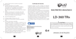
data†aker 51.
Analog Inputs
• 1 differential or 3 single ended, can be used in any mix.
• Sampling rate 25 samples/sec
• Input impedance 1MΩ, or >100 MΩ selectable
• Common mode range ±3.5 VDC
• Common mode rejection >90 db (110 db typical)
• Series mode line rejection >35 db
• Sensor excitation of 4.5V, 250.0µA or 2.500mA each channel.
• Full, half and quarter bridges, voltage or current excitation.
• Multiplexer type: solid state (CMOS)
COMMS Port
DC Voltage
1
3
DC Current
1
4
Resistance
1
2
1
2
Frequency
±25 mV
±250 mV
±2500 mV
±0.25 mA
±2.5 mA
±25. mA
10 Ohms
100 Ohms
500 Ohms
7000 Ohms
0.1-20,000 Hz
*+
–
The
data†aker
110 mm
Source
AC
DC
DC
9V Alkaline Battery
6V Gel Cell Battery
Range
+ Terminal – Terminal
9 – 18Vac AC/DC~
11 – 24Vdc AC/DC~
11 – 24Vdc AC/DC~
6.2 – 10Vdc Alkaline +
5.6 – 8Vdc
Lead +
AC/DC~
AC/DC~
Gnd
Bat. –
Bat. –
The external 6 Volt gel cell connection provides temperature
compensated charging with voltage (6.90V) and current (1A)
limiting for a three cell battery, when an external AC or DC power
supply is also connected.
When the data†aker 51 is powered by a 9V alkaline
battery and an external AC or DC source, the 6.9V regulator's
(see schematic) output is increased to 10V so that power is
drawn from the external source in preference to the battery.
7
N/C
6
TxD
2
N/C
1
Interface
Ground
Baud Rate s2
off
1200
off
9600
off
300
on
2400
on
4800
ON
AA Lithium Battery
on lower circuit board
+–+
AC/DC
Power
Input
Convert
Lamp
1
Battery
Alkaline
9V
Lead Acid
6V
Display
Connector
250 mm
Caution - To avoid damage use 6 Volt
lead acid battery only, ensure correct
polarity before connecting the battery
AC/DC
Power
External Battery
Connections
6.9V
1000µF
Protection
Circuit
Gnd
External AC Power
Lead +
11-24Vdc
+
Bat –
Alkaline +
Simplified Power Supply Schematic
~
~
~
9-18Vac
0.22Ω
Gnd
Wiring Battery
Wiring Power
6.9V Switch Mode
Regulator
(–9.2mV/°C)
~
~
270 mm
DC
Gnd.
–
or
External DC Power
~
~
Gnd
+
Alkaline +
Bat. –
–
6.2–10V
Lead +
External Alkaline Battery
Alkaline +
–
5.6–8V
+
Bat. –
Lead +
External Gel Cell Battery
s3 s5 Add. Range
off x
0 - 15
on off
0-7
on on
0-7
off x
0 - 15
on x
0 - 15
x = don't care
Mux Power s4
permanent on
switched off
Country Setting
The Country Setting determines the
default integration period (16.7mS
for US and 20mS for others) for the
analog to digital converter, and the
default date format (see "Date" on
page 6).
Baud Rate and Address
The data†aker 51 RS232
COMMS port baud rate must match
that of the host computer. See
"COMMS Port" on page 13. If either
300 or 9600 baud is selected, the
logger address range is reduced to
0 -7.
Multiplexer Power
The power consumption of the
data†aker 51 can be kept to a
minimum if the input multiplexer is
powered down while the logger is in the sleep state. For
the data†aker 51 this is set using DIP switch s4.
The factory preset is for the multiplexers to power
down while the data†aker 51 ais sleep. The current
saving is approximately 150µA, which is current draw of
the 4 CMOS multiplexer integrated circuits (CD4052).
See "Multiplexer Powering" on page 15.
75 mm
~~
Range
0 or 1 State
0 to 16 State
65535 Counts
65535 Counts
51 can be powered as follows
N/C
RxD
3
+5 volts switched
Ground
1
Height: 60mm
2
3 Digital I/O Weight: 1.5kg
4
Ground
1
1(out)
Power
Counters
2
AC/DC
3
Ground
G
Wake
• 4 TTL/CMOS compatible digital input channels for digital state,
digital events, low speed counters (10 Hz, 16 bit, presettable).
Digital input terminals are shared with digital output channels
• 4 Digital open collector outputs rated to 200mA at 30V
• 3 high speed counters, (1KHz or 1MHz, 16 bit, presettable).
• All analog channels may also be used as digital inputs, with a
user definable threshold.
Power Supply and Battery also page 15
8
N/C
4
1 Analog Input
Digital Inputs and Outputs
Channels
4
1
4
3
N/C
5
R
Diff refers to differential or double ended channels, and SE refers
to single ended channels (see "Glossary" on page 23).
Input Type
Digital Bit
Digital Nibble
LS counter
HS counter
9
Country s1
US (60Hz) on
Other (50Hz) off
Shown set to the
factory defaults
RS232 COMMS
Port (Isolated)
Resolution
1µV
10µV
100µV
200nA
1µA
10µA
0.5m Ω
5mΩ
50mΩ
500mΩ
0.01%
N/C
Dip Switch
1 23 45 67 8
For each analog input type, the data†aker 51 provides
three decade ranges which are selected automatically:
Input Type Channels Range Units
Diff SE
RS232 COMMS
also page 13
The data†aker 51 RS232 COMMS Port is
serial RS232 compatible. The output signal level is
approximately ±4 Volts, allowing communications
over distances in access 100 meters at 1200 baud.
Greater distances are possible at 300 baud. The
maximum practical distance is also dependent on
the host computer's RS232 characteristics. (Note:
the RS232 "standard" specifies 2000pF maximum
cable capacitance, and no maximum distance).
The data†aker 51 RS232 COMMS Port is
electrically isolated to 500V.
Address s5
0 off
1 off
2 off
3 off
4 off
5 off
6 off
7 off
8 on
9 on
10 on
11 on
12 on
13 on
14 on
15 on
See text to right
Each model in the data†aker data logger range has a
number of characteristics that differentiate it from the other
models. This Appendix describes these characteristics for the
ON
Introduction
Page A1
DT 51
1 23 45 67 8
Appendix — data†aker
s6 s7
off off
off off
off on
off on
on off
on off
on on
on on
off off
off off
off on
off on
on off
on off
on on
on on
s8
off
on
off
on
off
on
off
on
off
on
off
on
off
on
off
on
data†aker 51 Address
The data†aker 51 can be
given an address, despite the fact
that the logger does not support
networking.
The address of a data†aker
51 can be used for
◆ identification in the STATUS or
STATUS1
commands (see
"STATUS" on page 10)
◆ identification of returned data if
/L Address Switch is enabled (see
"Swityches - /L" on page11)
If 300 or 9600 baud rate is
selected, then the address range is
limited to 0 - 7.
Power Consumption
The data†aker 51 will consume very little power
if it is allowed to sleep. Less power is consumed if the
data†aker 51 is powered through the battery
terminals, rather than through the AC/DC terminals,
because the battery charger circuit draws additional
current, especially if it is charging a depleted battery.
Power Source
battery
battery
AC/DC
AC/DC
AC/DC
AC/DC
Condition
awake
sleep
awake
awake & charging
sleep
sleep & charging
Current (typical)
100mA
0.36mA
105mA
600mA
5mA
500mA