1
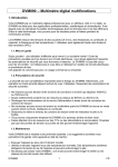
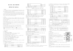
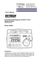
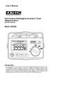
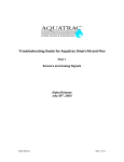
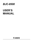
DVM890 Multifunctional Digital Multimeter Multifunctionele Digitale Multimeter Multimètre digital multifonctions USER MANUAL GEBRUIKERSHANDLEIDING MANUEL D’UTILISATION DVM890 -- Multifunctional Digital Multimeter 1. Introduction Your DVM890 is a professional digital multimeter with a 3 ½ digit LCD display. It is ideally suited for professional, academic and home applications. The device is equipped with the latest in IC and display technology. Thanks to this technology, the DVM890 will provide you with precise and reliable measurements for years to come. The DVM890 measures DC and AC voltage, DC and AC current, resistance, continuity, capacitance, frequency and temperatures. You can also diodes and transistors (hFE). 1.1. Warning Be very careful when performing measurements as improper use of this device may result in serious injuries or even death. Take all usual precautions for working with electrical circuits and mind the safety prescriptions listed below. Do not use this device if you are unfamiliar with electrical circuits and testing procedures. This device is not intended for commercial or industrial use. 1.2. Safety Prescriptions This multimeter was designed to ensure the safest operation possible. Nevertheless, safe operation mainly depends on you, the user. Respect the following safety prescriptions : • Never apply more than 1000VDC or 700Vrms AC between an input jack and ground. • Use extreme caution when working with voltages in excess of 60VDC or 30Vrms AC. • Always discharge the filter capacitors in a power supply circuit before attaching the test leads. • Never connect a voltage source to the DVM890 when it is in current (DCA or ACA) mode, resistance or continuity mode. • Always turn off the power and disconnect the test leads prior to replacing the battery or fuse. • The user should only operate the multimeter when the back cover is in place and securely fastened. • When carrying out measurements on TVs or switching power circuits, you should always remember that high voltage pulses may occur at the test points. These pulses may damage the meter. 1.3. Maintenance Your DVM890 is an example of superior design and craftsmanship. The following suggestions will help you keep the device in perfect working order : • Do not expose the device to water. Wipe it dry immediately if it should get wet. • Use and store the multimeter under normal temperatures. Extreme temperatures may shorten the life of the device or damage the battery. • Handle the multimeter with care. Dropping it may damage the circuit boards or the housing and may cause the DVM890 to malfunction. • Replace an old or weak battery with a fresh one of the required size and type. Remove the battery during long periods of inactivity. This will protect the multimeter from possible leakage. • Disconnect the test probes prior to opening the housing. DVM890 1 GB • A blown fuse should be replaced with an identical one. F : F 0.2A/250V • Do not use this device in case of malfunction or if anomalies are detected. Have it repaired by qualified personnel. • Do not use the multimeter unless the back cover is in place and fully fastened. • Use a soft cloth and a mild detergent for cleaning purposes. Never use abrasives or solvents on the meter. 2. Description of the Front Panel 1) LCD display 2) Power ON/OFF button 3) Capacity input sockets 4) "20A MAX" jack 5) "mA" jack 6) "COM" jack 7) "VΩHz" jack 8) Temperature probe jack 9) RANGE and FUNCTION switch 10) Transistor test socket 2.1. Range and Function Selector This rotary switch is used to install the various functions and each of the 32 ranges. 2.2. Power Switch This push-button activates and deactivates the device. The DVM890 is also equipped with an energy-saving feature : the meter is automatically deactivated when the RANGE and FUNCTION selector has not been used for 15 minutes. The user will have to press the ON/OFF button twice to switch the device on again when the energy-saving feature has deactivated the DVM890. 2.3. Input Jacks The DVM890 is equipped with 4 input jacks that are protected against overload. The limit values are listed in the table below. The black test lead should be connected to the "COM" jack. The red test lead should be connected to one of the other three input jacks, depending on the required function. DVM890 2 GB FUNCTION 200mV V & V∼ Hz Ω / mA & mA∼ 10A & 20A∼ RED LEAD CONNECTION INPUT LIMITS 250V DC or rms AC 1000V DC, 700V AC (sine wave) 250V DC or rms AC 250V DC or rms AC 250V DC or rms AC 200mA DC or rms AC 10A DC or rms AC continuous 20A for max. 15 seconds VΩHz VΩHz VΩHz VΩHz VΩHz mA A 3. Operating instructions 3.1. Measuring DC Voltage 1. Connect the black test lead (-) to the "COM" jack and the red test lead (+) to the "VΩHz" jack. 2. Select the appropriate V range with the FUNCTION switch and connect the test leads to the source or load to be tested. 3. The measured value and the polarity of the red test lead are displayed on the LCD. Remark : Set the FUNCTION switch to the highest range and gradually work your way down if the voltage range is unknown beforehand. 3.2. Measuring AC Voltage 1. Connect the black test lead (-) to the "COM" jack and the red test lead (+) to the "VΩHz" jack. 2. Select the appropriate V∼ range with the FUNCTION switch and connect the test leads to the source or load to be tested. 3. The measured value appears on the LCD display. Remark : Set the FUNCTION switch to the highest range and gradually work your way down if the voltage range is unknown beforehand. 3.3. Measuring DC Current 1. Connect the black test lead (-) to the "COM" jack and the red test lead (+) to the "mA" jack for measurements of max. 200mA. Move the red test lead to the "10A" jack for measurements of max. 20A (for max. 15 sec. at a stretch). 2. Select the A range with the FUNCTION switch. 3. Connect the test leads IN SERIES with the load under measurement. 4. The polarity of the red test lead and the measured current are displayed on the LCD. Remark : Set the FUNCTION switch to the highest range and gradually work your way down if the current range is unknown beforehand. DVM890 3 GB 3.4. Measuring AC Current 1. Connect the black test lead (-) to the "COM" jack and the red test lead (+) to the "mA" jack for measurements of max. 200mA. Move the red test lead to the "10A" jack for measurements of max. 20A (for max. 15 sec. at a stretch). 2. Select the A ∼ range with the FUNCTION switch. 3. Connect the test leads IN SERIES with the load under measurement. 4. The measured current is displayed on the LCD. Remark : Set the FUNCTION switch to the highest range and gradually work your way down if the current range is unknown beforehand. 3.5. Measuring Resistance 1. Connect the black test lead (-) to the "COM" jack and the red test lead (+) to the "VΩHz" jack. 2. Select the appropriate "Ω" range with the FUNCTION switch and connect the test leads with the load to be measured. Remarks : v The meter may need a few seconds to produce a stable reading for resistance measurements in excess of 1MΩ. v The overrange indication (“1.”) will appear on the display if the input is not connected or if the resistance being measured exceeds the max. value of the selected range. v Disconnect the circuit to be tested and make sure that all capacitors are fully discharged before measuring the in-circuit resistance. 3.6. Measuring Capacitance 1. Connect the test capacitor to the "Cx" input connection (9 in figure on p. 2). Do NOT connect the capacitor to one of the 4 input jacks (viz. "10A", "mA", "COM" or "VΩHz" jack). 2. Select the "Cx" range with the FUNCTION switch. Remarks : v Do not connect an external voltage to the input terminal. Discharge capacitors before connecting them. v Units : 1pF = 10-6µF 1nF = 10-3µF. 3.7. Testing Diodes & Continuity 1. Connect the black test lead (-) to the "COM" jack and the red test lead (+) to the "VΩHz" jack. 2. Select the / range with the FUNCTION switch and connect the test leads. 3. Connect the red test lead to the anode and the black test lead to the cathode of the diode to be tested. 4. For continuity tests : connect the test leads to two random points of the circuit to be tested. The incorporated buzzer is activated if the resistance between the two test leads is lower than ± 30Ω. DVM890 4 GB 3.8. Transistor Test (hFE) 1. Select the "hFE" range with the FUNCTION switch. 2. Determine whether the transistor is of the NPN- or PNP-type and locate the emitter, the base and the collector. Insert the leads into the proper holes in the socket on the front panel. 3. The display will show the approximate hFE-value at the moment of testing. Base current 10µA, Vce 2.8V. 3.9. Measuring Temperature 1. Measure temperatures with the K-type thermocouple : select the "T" range with the FUNCTION switch and insert the plug of the K-thermocouple in the green "K PROBE" socket. 2. The ambient temperature will be displayed in °C if the "T" range is selected without connecting the K-thermocouple. Remark : Do not hesitate to push firmly in order to insert the temperature probe in the socket. 3.10. Measuring Frequency 1. Connect the black test lead (-) to the "COM" jack and the red test lead (+) to the "VΩHz" jack. 2. Select the "KHz" range with the FUNCTION switch and connect the test leads to the source or load to be tested. Remarks : v Do not apply more than 220Vrms to the input. v Use shielded cable for measuring a weak signal in a noisy environment. 3.11. Automatic Power off 1. The device will be deactivated automatically when the FUNCTION and RANGE switch has not been used for 15 minutes. This energy-saving feature extends the life of your battery. 2. The meter will be reactivated if the FUNCTION and RANGE switch is turned or if the power switch is pressed again. 4. Specifications Maximum accuracy is guaranteed for a one-year period after calibration. Ideal circumstances require a temperature of 23°C (± 5°C) and a max. relative humidity of 75%. 4.1. General Max. Voltage between Terminal and Earth Display Fuse Protection Power Supply Ranging Method Polarity Indication Overrange Indication DVM890 1000VDC or 700Vrms AC (sine wave) 3 ½ digit LCD, 2 to 3 readings/sec. 200mA-range : F 0.2A/250V 20A-range :--9V-battery manual " - " is displayed " 1. " is displayed automatically 5 GB Battery-Low Indication Operating Temperature Storage Temperature Dimensions Weight " " is displayed 0°C to 40°C -10°C to 50°C 88 x 170 x 38mm 340g (incl. battery) 4.2. DC Voltage Range Resolution Accuracy 200mV 100µV 2V 1mV 20V 10mV 200V 100mV 1000V 1V Input Impedance : 10MΩ for all ranges Overload Protection : 1000V DC or peak AC for all ranges ± 0.5% of rdg ± 1 digit ± 0.8% of rdg ± 2 digits 4.3. AC Voltage Range Resolution Accuracy 200mV 100µV ± 1.2% of rdg ± 3 digits 2V 1mV ± 0.8% of rdg ± 3 digits 20V 10mV 200V 100mV 700V 1V ± 1.2% of rdg ± 3 digits Input Impedance : 10MΩ for all ranges Frequency Range : 40 to 400Hz Overload Protection : 750Vrms or 1000V peak continuous (except for the 200mVAC-range : max. 15 sec. above 300Vrms). 4.4. DC Current Range Resolution Accuracy 2mA 1µA ± 0.8% of rdg ± 1 digit 20mA 10µA 200mA 100µA ± 1.2% of rdg ± 1 digit 20A 10mA ± 2.0% of rdg ± 5 digits Overload Protection : F 0.2A fuse (20A-range is not protected by a fuse) Max. Input Current : 20A, 15 sec. DVM890 6 GB 4.5. AC Current Range Resolution Accuracy 20mA 10µA ± 1.2% of rdg ± 3 digits 200mA 100µA ± 2.0% of rdg ± 3 digits 20A 10mA ± 3.0% of rdg ± 7 digits Overload Protection : F 0.2A fuse (20A-range is not protected by a fuse) Frequency Range : 40 to 400Hz Max. Input Current : 20A, 15 sec. 4.6. Resistance Range Resolution Accuracy 200Ω 2kΩ 20kΩ 200kΩ 2MΩ 20MΩ 200MΩ 0.1Ω 1Ω 10Ω 100Ω 1kΩ 10kΩ 100kΩ ± 0.8% of rdg ± 3 digits Range Resolution Accuracy 2000pF 20nF 200nF 2µF 20µF 1pF 10pF 100pF 1nF 10nF ± 2.5% of rdg ± 5 digits ± 0.8% of rdg ± 1 digit ± 1% of rdg ± 2 digits ± 5% of rdg ± 10 digits 4.7. Capacitance 4.8. Temperature Range Temperature Range Resolution - 50°C to 400°C 400°C to 1000°C 0°C to 40°C Using a K-type thermocouple probe T 1°C Accuracy ± 0.75% of rdg ± 3°C ± 1.5% of rdg ± 15°C ± 2°C Using the built-in temperature sensor 4.9. Frequency Range Resolution Accuracy ± 1% of rdg ± 1 digit 20kHz 10Hz Overload Protection : AC 220Vrms DVM890 7 GB 5. Accessories • • • • • • set of test leads K-type thermocouple (400°C) 1 battery of 9V 1 user manual 1 holster 1 adapter for capacitance measurements 5.1. How to use the holster The holster protects the device and ensures comfortable operation. Consult the figures below : 1. Use one of the two supports to place the device on a table or a desk (fig. A & B). 2. Hang the meter on the wall using the smaller of the two supports. (fig. C) : remove the smaller support and insert it in the slots at the top of the holster. Use the support to hang the device on a nail in the wall. 3. Each of the two supports in fig. D can hold a test lead. 6. Replacing the Battery and the Fuse The " " symbol appears when the battery needs to be replaced. Proceed as follows : 1. Disconnect the test leads from all live sources, switch off the device and remove the test leads from the input terminals BEFORE opening the housing. This is necessary in order to avoid the risk of electroshocks. 2. Remove the screws in the back cover and retrieve the battery. 3. Insert a new 9V-battery (NEDA1604 or IEC6F22). 4. Replace the cover and tighten the screws. The fuse rarely needs to be replaced and a blown fuse is nearly always due to an error on behalf of the operator. Open the housing (see above) and replace the blown fuse with an identical one : F : F 0.2A/250V. DVM890 8 GB