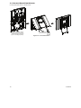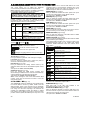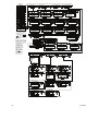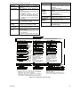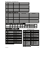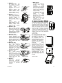
1
PowerMaxComplete
Fully Supervised Wireless Alarm Control System
Installer Guide
TABLE OF CONTENTS
1. INTRODUCTION ....................................................... 3
2. SPECIFICATIONS..................................................... 3
2.1 General Data....................................................... 3
2.2 RF Section .......................................................... 3
2.3 Electrical Data ..................................................... 4
2.4 Communication ................................................... 4
2.5 Physical Properties ............................................. 4
3. INSTALLATION ......................................................... 4
3.1 Unpacking the Equipment................................... 4
3.2 Supplying Power to the Unit................................ 4
3.3 System Planning & Programming ....................... 4
3.4 Mounting ............................................................. 4
3.5 Wiring .................................................................. 4
3.6 Backup Battery Insertion..................................... 7
3.7 Optional GSM/GPRS Module Mounting ................ 7
3.8 DUAL RS-232 Optional Module Mounting .......... 8
3.9 Optional Expander Module Mounting ................. 8
3.10 Power Cable Connection .................................. 8
3.11 Control Panel Final Closure ............................ 10
4. PROGRAMMING..................................................... 11
4.1 INTRODUCTION .............................................. 11
4.1.1 General Guidance.......................................... 11
4.1.2 Entering an Invalid Installer Code ..................... 11
4.1.3 Installer’s Menu .............................................. 11
4.1.4 Setting a New Installer Code ......................... 11
4.1.5 Setting a New Installer Code in
PowerMaxComplete that has 2 Installer Codes....... 11
4.2 ENROLLING WIRELESS DEVICES AND KEYFOB
TRANSMITTERS......................................................... 12
4.2.1 General Guidance.......................................... 12
4.2.2 Enrolling Type ................................................ 12
4.2.3 Enroll/Delete Sensors .................................... 12
4.2.4 Enroll/Delete Keyfob Transmitters ....................... 12
4.2.5 Enroll/Delete Wireless Commander...................... 12
4.2.6 Enroll/Delete 2-Way Keypad .......................... 12
4.2.7 Enroll/Delete Wireless Siren........................... 12
4.2.8 Enroll/Delete Proximity Tags .......................... 12
4.3 DEFINING ZONE TYPES, NAMES, CHIME ZONES
& PARTITION .............................................................. 14
4.4 DEFINING CONTROL PANEL PARAMETERS .... 15
4.4.1 Preliminary Guidance..................................... 15
4.4.2 Entry Delays 1&2 ........................................... 15
4.4.3 Exit Delay ....................................................... 15
4.4.4 Bell Time ........................................................ 15
4.4.5 Abort Time...................................................... 15
4.4.6 Alarm Cancel.................................................. 16
4.4.7 Quick Arm ...................................................... 16
4.4.8 Bypass............................................................ 16
4.4.9 Exit Mode ....................................................... 16
4.4.10 Piezo Beeps ................................................. 16
4.4.11 Trouble Beeps.............................................. 16
4.4.12 Panic Alarm.................................................. 16
4.4.13 Swinger Stop................................................ 16
4.4.14 Cross Zoning................................................ 16
4.4.15 Supervision .................................................. 16
D-302754
4.4.16 NOT READY ................................................ 16
4.4.17 AUX Button A............................................... 16
4.4.18 AUX Button B 2-W-KF ................................... 17
4.4.19 Jam Detect................................................... 17
4.4.20 Latchkey....................................................... 17
4.4.21 “Not Active” .................................................. 17
4.4.22 Back Light .................................................... 17
4.4.23 Duress.......................................................... 17
4.4.24 Piezo Siren................................................... 17
4.4.25 Reset Option ................................................ 17
4.4.26 Tamper Option ............................................. 17
4.4.27 Siren On Line ............................................... 17
4.4.28 Memory Prompt ........................................... 17
4.4.29 Disarm Option .............................................. 17
4.4.30 Bell/Rep. Option........................................... 17
4.4.31 Low-Bat Ack................................................. 18
4.4.32 Screen Saver ............................................... 18
4.4.33 Confirm Alarm .............................................. 18
4.4.34 AC FAIL REP ............................................... 18
4.4.36 User Permission .......................................... 18
4.4.38 Battery Type................................................. 18
4.4.39 Key Zones Options (Optional) ..................... 18
4.5 DEFINING COMMUNICATION PARAMETERS... 20
Preliminary Guidance.............................................. 20
4.5.1 PSTN / GSM (Fig. 4.5).................................... 20
4.5.2 GPRS / BB (Fig. 4.5) ..................................... 20
4.5.3 C.S. Reporting (Fig. 4.5)................................ 21
4.5.4 Private Report (Fig. 4.5) ................................. 23
4.6 GSM Auto Detection.............................................. 26
4.7 POWERLINK Auto Detection ................................ 26
4.8 DEFINING OUTPUT PARAMETERS ................... 26
4.8.1 Preliminary Guidance .................................... 26
4.8.2 Define PGM ................................................... 26
4.8.3 Defining INT/STRB ........................................ 26
4.8.4 PGM General Definition................................. 26
4.9 DEFINE VOICE ..................................................... 27
4.9.1 Record Speech .............................................. 27
4.9.2 Voice Box Mode............................................. 27
4.10 DIAGNOSTIC TEST ............................................ 28
4.10.1 GPRS Communication Test ........................ 28
4.10.2 LAN Connection Test................................... 28
4.11 USER FUNCTIONS ............................................ 30
4.12 RETRIEVING FACTORY DEFAULTS ................ 30
4.13 SERIAL NUMBER ............................................... 30
4.14 CALLING UPLOAD/DOWNLOAD SERVER....... 30
4.15 ENABLING/DISABLING PARTITIONS ............... 31
4.16 WALK-TEST ........................................................ 31
5. TESTING PROCEDURES ...................................... 31
5.1 Preparations...................................................... 31
5.2 Diagnostic Test ................................................. 31
5.3 Keyfob Transmitter Test ................................... 31
5.4 PGM output ON/OFF Test ................................ 31
1
5.5 Emergency Transmitter Test............................. 32
6. MAINTENANCE....................................................... 32
6.1 Dismounting the Control Panel ......................... 32
6.2 Replacing the Backup Battery........................... 32
6.3 Fuse Replacement............................................ 32
6.4 Replacing/Relocating Detectors ....................... 32
7. READING THE EVENT LOG .................................. 32
APPENDIX A. Partitioning ........................................... 33
Programming Partitions .......................................... 33
Defining Zones ........................................................ 33
Enrolling Keyfobs and Keypads .............................. 33
User Interface and Operation.................................. 34
Common Areas ....................................................... 34
APPENDIX B. Detector Deployment & Transmitter
Assignments ................................................................ 36
B1. Detector Deployment Plan .................................. 36
B2. Keyfob Transmitter List....................................... 36
B3. Emergency Transmitter List ................................ 37
B4. Non-Alarm Transmitter List ................................. 37
APPENDIX C. PGM Output Assignment ..................... 37
APPENDIX D. Event Codes ........................................ 37
Contact ID Event Codes ......................................... 37
SIA Event Codes..................................................... 37
4/2 Event Codes...................................................... 38
Understanding the Scancom Reporting Protocol Data
Format..................................................................... 39
APPENDIX E. Programmable Zone Types ................. 39
E1. Delay Zones....................................................... 39
E2. Emergency Zones.............................................. 39
E3. Fire Zones ........................................................ 39
E4. Flood Zone ....................................................... 39
E5. Gas Zone.......................................................... 39
E6. Home/Delay Zones........................................... 39
E7. Interior Zone ..................................................... 39
E8. Interior Follower Zones..................................... 39
E9. Key Zones (Optional) ....................................... 39
E10. Non-Alarm Zones ........................................... 39
E11. Perimeter Zones ............................................. 40
E12. Perimeter Follower Zones .............................. 40
E13. Temperature Zone.......................................... 40
E14. 24-Hour Zones ............................................... 40
APPENDIX F. PowerMaxComplete Compatible Devices
..................................................................................... 40
F1. PowerMaxComplete Compatible Detectors ...... 40
F2 Compatible Transmitters ................................... 40
F3 Compatible WL Siren ........................................... 41
F4. PowerMaxComplete Compatible GSM Modem 42
F5. Optional Speech Box (Voice enabled only) ......... 42
MESSAGE TO THE INSTALLER
The PowerMaxComplete control panel is supplied with 2 instruction manuals:
Installer Guide (this manual - for your exclusive use)
User’s Guide (for your use during installation only - Must be handed over to the master user after testing the system).
Appendices A.1 and A.2 will help you prepare an installation plan. Please take time to fill out the forms - your job will
become much easier and confusion will be prevented. Filling out the forms will also help you create a list of detectors and
transmitters that must be obtained for the particular application. Compatible detectors and transmitters are listed and
described briefly in Appendix F.
Remember - it is advisable to power up the control panel temporarily after unpacking and program it on the work bench, in
accordance with the installation plan.
The programming flow charts in the programming section show all options available for each parameter. Factory defaults
are marked with a dark box to their right, and other options (that can be selected instead) are marked by clear boxes. This
method allows you to put a checkmark in the appropriate clear box whenever you deviate from the factory defaults.
Most of the programming section paragraph numbers correlate with the programming menu numbers. For example,
paragraph 4.4.19 describes the "Jam detect", that exists in menu 4 (define panel), sub-menu 19 (Jam detect).
Although setting the correct time and date is one of the user tasks, we recommend that you set the time and date in the
course of programming. Access to the “User Settings” for the installer is possible through item 10 on the installer‘s menu or
through the user menu (see User’s manual section 7).
After programming, proceed to install the system as detailed in the Installation Instructions, from paragraph 3.4 onward.
The installer should verify line seizure. Be aware of other phone line services such as DSL. If DSL service is present
on the phone line, you must install a filter. It is suggested to use the DSL alarm filter model Z-A431PJ31X
manufactured by Excelsus Technologies, or equivalent. This filter simply plugs into the RJ-31X jack and allows
alarm reporting without breaking the internet connection. If the user has a Voice over IP phone system only, the
control panel will not be able to communicate with the central station via the PSTN telephone line. In this case, the
user will either need to install an additional telephone line, or connect a GSM module.
2
D-302754
1. INTRODUCTION
Compatibility: This manual refers to PowerMaxComplete
v2.0.00 and above.
The PowerMaxComplete is a user and installer-friendly,
30-zone fully-supervised wireless control system. The
system is designed to function in an appealing way to the
user and also offers features that make installers’ life
easier than ever before:
The PowerMaxComplete includes an optional partition
feature. Partitioning allows you to have up to three
independently controllable areas with different user codes
assigned to each partition or one user code assigned to a
combination of up to 3 partitions. Partitions can be armed
or disarmed individually or altogether in one operation. For
example, you can define the garage as partition 1, the
basement as partition 2 and the house as partition 3. Since
each partition is independent of other partitions, you can
arm or disarm each partition as desired without altering the
states of the other partitions.
EASY TO INSTALL
plug-in RS-232 module
connection of a local computer.
• Optional
that
enables
EASY TO MAINTAIN
• Status, alarm memory and trouble data are displayed
upon request.
• Diagnostic test provides visual and audible indication of
the signal level of each detector.
• Remote control and status verification from distant
telephones.
• Event log stores and displays information.
• Upload / download from distant computer via telephone
line or cellular modem.
QUICK PROGRAMMING
• Simple programming logic, fully menu driven.
• Multiple-choice selection of options for each parameter.
• Unequivocal visual prompts and audible signals.
• Installer access to the user menu.
2. SPECIFICATIONS
2.1 General Data
Zones Number: 28 wireless, 2 hardwired (zones 29 & 30).
Hardwired Zone Requirements: 2.2 kΩ E.O.L. resistance
(max. resistance of wires 220 Ω).
Zone Types: Interior follower, interior, perimeter,
perimeter follower, delay 1, delay 2, 24h silent, 24h
audible, fire, non-alarm, emergency, gas, flood,
temperature and home / delay.
User Codes: 8 codes, 4 digits each (9999 different
combinations). Code 0000 is not allowed.
Control Facilities:
- Integral keypad
- PowerCode / Code-Secure™ hand-held transmitters
- Wireless commander
- SMS commands via optional GSM/GPRS module
- Remote telephone
- Local or remote computer
Display: Single line, Backlit 16-character LCD.
Arming Modes: AWAY, HOME, AWAY-INSTANT, HOMEINSTANT, LATCHKEY, FORCED, BYPASS.
Alarm inhibited during a single arming period (swinger
stop) after: 1, 2, 3, alarm/tamper/fault, or not inhibited
(programmable / selectable).
Alarm Types: Silent alarm, siren alarm or sounder
(internal) alarm, in accordance with zone attributes.
Siren Signals: Continuous (intrusion / 24 hours / panic);
triple pulse - pause - triple pulse... (fire).
Siren (bell) Timeout: Programmable (4 min. by default)
Internal Sounder Output: At least 85 dBA at 10 ft (3 m)
Supervision: Programmable time frame for inactivity alert
Special Functions:
- Speech and sound control
- Chime zones
- Diagnostic test and event log
- Local and Remote Programming over Telephone, GSM/
GPRS connections
- Computer control and data download/upload
- Calling for help by using an emergency transmitter
D-302754
- Tracking inactivity of elderly, physically handicapped and
infirm people
- Family message center (recording and playback)
- Two-way voice communication
Data Retrieval: Status, alarm memory, trouble, event log.
Real Time Clock (RTC): The control panel keeps and
displays time and date.
Compliance with U.S. Standards:
Meets CFR 47 Part 15 and Part 68 requirements.
Compliance with European CE Standards:
EN 50082-1, EN301489-3,7,
EN6100-4-6, EN60950,
EN300220, EN50130-4, EN50130-5, EN 50131-1, EN 50131-3
Grade 2 Class 2, ATS-3
The PowerMaxComplete is compatible with the RTTE
requirements - Directive 1999/5/EC of the European
Parliament and of the Council of 9 March 1999.
According to the European standard EN50131-1, the
PowerMaxComplete security grading is 2 – "low to medium
risk" and environmental classification is II – "indoor general"
and the power supply type is A.
GSM standards:
Europe : Complies with CE standards 3GPP TS 51.0101, EN 301 511, EN301489-7
USA: CFR 47 Part 22 (GSM850) and Part 24 (GSM
1900). UL1637, UL1635, UL1023, UL985, ULC-S545-02,
ULC C1023.
EMC standard: CFR 47 Part 15.
SAR standards: FCC rule 2.1093, FCC Docket 96-326 &
Supplement C to OET Bulletin 65
GPRS standards:
General: ETSI EN 301 511 v.9.0.2, CENELEC EN
60950:2001, ETSI EN 301 489-1: v.1.4.1, ETSI EN 301
489-7: v.1.2.1.
GE864 module is compliant with the following
standards: EN 301 511 and 3GPP 51.010-1, EN 301
489-1, EN 301 489-7, ETSI GSM 07.07.
2.2 RF Section
Operating Frequencies (MHz): 315 (in USA & Canada),
433, 868.95 or other UHF channel per local requirement in
the country of use.
3
Receiver Type: Super-heterodyne, fixed frequency
Receiver Range: 600 ft (180 m) in open space
Antenna Type: Spatial diversity
Coding: PowerCode and/or CodeSecure™
2.3 Electrical Data
Backup
period
Power Supply: Internal switching power supply 100VAC
to 240VAC, 50/60 Hz, 0.5A / 12.5 VDC, 1.6A.
Current Drain: Approx. 40 mA standby, 1400 mA at full
load.
Site External Siren Current (EXT): 450* mA max @ 10.5
VDC minimum when powered by AC & DC (battery).
Site Internal Siren Current (INT): 450* mA max. @ 10.5
VDC minimum when powered by AC & DC (battery)
PGM Output Current: 100* mA max.
Wired Detectors (zones 29&30) Total (Sum) Current: 36*
mA max.
High Current / Short Circuit Protection: All outputs are
protected (automatic reset fuse).
* Total PowerMaxComplete output current (of INT & EXT
sirens, PGM output and detectors) cannot exceed 550 mA.
Backup Battery Options:
Maximum external devices current (1)
2200 mAh 81300 mAh
1800 mAh
Battery Pack (4)
6 Battery
8-Battery
Pack (2)
Pack (3)
4h
8h
12h
24h
36h
48h
210mA
90mA
45mA
0mA
(no backup)
(no backup)
300mA
160 mA
90 mA
25 mA
5mA
(no backup)
380mA
200mA
120 mA
45mA
15mA
0mA
1
Devices that are connected between 12V terminal
and GND of PowerMaxComplete, that includes
internal GSM and proximity reader.
2
7.2V 1300 mAh, rechargeable NiMH battery pack,
p/n GP130AAH6BMX, manufactured by GP.
3
9.6V 1800 mAh, rechargeable NiMH battery pack,
p/n GP180AAH8BMX, manufactured by GP.
4
9.6V 2200 mAh, rechargeable NiMH battery pack
(special order).
Maximum battery recharge time: 72 hours
Battery Test: Once every 10 seconds.
2.4 Communication
Built-in Modem: 300 baud, Bell 103 protocol
Data Transfer to Local Computer: Via RS232 serial port
Report Destinations: 2 central stations, 4 private
telephones.
Reporting Format Options: SIA, Pulse 4/2 1900/1400 Hz,
Pulse 4/2 1800/2300 Hz, Contact ID, Scancom.
Pulse Rate: 10, 20, 33 and 40 pps - programmable
Message to Private Phones: Tone or voice
Ring Detection: The unit does not support ring detection
without DC voltage present on the telephone lines.
2.5 Physical Properties
Operating Temp. Range: 14°F to 120°F (-10°C to 49°C)
Storage Temp. Range: -4°F to 140°F (-20°C to 60°C)
Humidity: 85% relative humidity, @ 30°C (86°F)
Size: 266 x 206 x 63 mm (10-7/16 x 8-18 x 2-1/2 in.)
Weight: 1.44Kg (3.2 pounds) (with battery)
Color: White
3. INSTALLATION
3.1 Unpacking the Equipment
Open the cardboard packing box and check whether all
items have been included. If you find out that an item is
missing, contact your vendor or dealer immediately.
3.2 Supplying Power to the Unit
Connect power to the PowerMaxComplete temporarily
(see figure 3.10). Alternatively, you may power up from the
backup battery, as shown in figure 3.3.
Disregard any “trouble” indications pertaining to lack of
battery or lack of telephone line connection.
3.3 System Planning & Programming
It pays to plan ahead - use the tables in appendices A and
B at the end of this guide to register the intended location
of each detector, the holder and assignment of each
transmitter.
4
Gather up all transmitters and detectors used in the
system and mark each one in accordance with your
deployment plan.
Program the system now as instructed in the
programming section.
3.4 Mounting
Required tool: Philips screwdriver #2.
PowerMaxComplete mounting process is shown in figure
3.1 - 3.11.
3.5 Wiring
Required tools: Cutter and slotted screwdriver - 3 mm
blade.
PowerMaxComplete wiring is shown in figure 3.2.
D-302754
Back unit
1
3
Release
screws
Mark 4 drilling points on mounting surface
5
4
Fasten the back unit with 4 screws
Drill 4 holes and insert wall anchors
Figure 3.1 – Back Unit Mounting
PHONE WIRING
Connect telephone cable to SET connector and telephone line cable to LINE connector (through the desired wiring cable entry).
PHONE WIRING IN NORTH AMERICA
8-POSITION
RJ-31X PLUG
RJ-31X JACK
GRAY
BROWN
RED
GREEN
GRAY
RJ-31X
CORD
1
2
3 4
RED
RJ-31X
7
6 5
LINE
FROM
STREET
HOUSE
PHONES
GRN
BROWN
Phone wiring in the UK: Line terminals must be connected to pins 2 and 5 of the wall jack.
For all installations: If DSL service is present on the phone line, you must route the phone line through a DSL filter (refer
to MESSAGE TO THE INSTALLER on page 2 for further details).
D-302754
5
ZONE 29 & SIREN WIRING
MAGNETIC CONTACT
OR ANY OTHER
CONTACT
(NOT A DETECTOR)
2.2 kΩ
SITE EXTERNAL SIREN
MG ELECTRONICS
MG441PDS OR SIMILAR
12 VDC SIREN
Alarm
N.C.
OPTIONAL EXPANDER MODULE
ZONES, SIRENS, AUDIO BOX AND WIRED DETECTORS WIRING
EXPANDER
Note
The EXPANDER module
is an optional module.
If this optional module is
not used, a small 4terminal strip is used
instead (2 terminals for
zone 29 and 2 terminals
for siren).
MIC
ZONE 29 /
ZONE 30
SPK
GND 12V
PGM
EXT.- SRN+ IN.- Z29 GND Z30
CONNECT WIRED DETECTORS AS FOLLOWS:
GND 12V(*)
ZONE 29 /
ZONE 30
GND 12V(*)
2.2 kΩ
TAMP Alarm Power
N.C. N.C.
Detector with
Tamper switch
Note
Regarding zones 29 & 30, the Control
Panel “sees” a specific resistance
according to the event, as follows:
Power Normal (no alarm & no tamper): 2.2 kΩ
Alarm
N.C.
Alarm event: 4.4 kΩ
Detector without Tamper event: Infinite resistance
Tamper switch
VOICE BOX
SITE
INTERNAL
SIREN OR
STROBE
SITE EXTERNAL
SIREN MG441PDS
OR SIMILAR
12 VDC SIREN
Caution:
When using the Expander,
the internal siren and
Zone 29 must be wired
via the Expander
and not via the
control panel.
Figure 3.2 - Wiring
Notes for EXPANDER module wiring:
*
Zone 29/GND and Zone 30/GND terminals can be
connected to a normally closed contact of a detector,
switch (for example a Tamper switch of any device), or
a pushbutton, via a 2.2 KΩ resistor. The 12V terminal
can be used to supply 12V (up to 36mA) to a
detector (if necessary).
** The EXT terminal can be used to trigger an external siren.
The INT terminal can be programmed for an "internal
siren" or "strobe" (see DEFINE OUTPUTS - DEFINE
INT/STRB in par. 4.8).
The 12V and "GND" terminals can be connected to a
siren (for constant DC power supply).
6
WARNING! When plugging terminals back into place, be
sure to align them carefully with the pins on the PCB.
Misaligned or reverse insertion of terminals may damage
internal PowerMaxComplete circuits!
IMPORTANT! The terminals for internal and external
sirens are DC outputs intended for 12V sirens. Connecting
a loudspeaker to any of these outputs will cause a short
circuit and will damage the unit.
D-302754
Notes for UL installations
a. The sirens connected to the sites INTERNAL or
EXTERNAL SIREN in the EXPANDER must be
suitable for burglar alarm applications. If UL fire
installation is required, all installed accessories must
comply with UL fire standards. Any external siren used,
must be UL listed and shall be rated to operate under
the voltage specified in the Specifications.
Note: The siren on the control panel PCB is non-UL
compliant.
b. A device that is connected to PGM terminal should not
exceed the current consumption defined for the 24-hour
backup period listed in the Backup Battery Options table
(see section 2.3).
c. The system shall be installed in accordance with Chapter
2 of the National Fire Alarm Code, ANSI/NFPA 70.
d. All wiring should be acceptable for class 1 systems as
defined by the National Electrical Code, ANSI/NFPA
70. No. 26 AWG or larger telecommunication line cord
shall be used.
e. The system shall be installed in accordance with CSA
C22.1 Canadian Electrical Code, Part 1.
f. A minimum spacing of 1/4 inch shall be maintained
between the telephone wiring and the low voltage wiring
(zones, bell circuit, etc). Do not route the LINE and SET
wires in the same wiring channel with other wires.
3.7
Optional
Mounting
GSM/GPRS
Module
Note: The GSM module is used with an internal antenna.
Caution: Do not install or remove the GSM module when
the system is powered by AC power or backup battery.
Plug in the GSM Module and fasten it with the screw:
Front
unit
GSM
Figure 3.4 - Optional GSM/GPRS Module Mounting
Insert the SIM card into the GSM module:
3.6 Backup Battery Insertion
Open battery compartment cover (see drawing below).
Insert one 6-battery pack or 8-battery pack and connect its
connector as shown below.
Front unit
Internal
GSM
antenna
Internal GSM
antenna cable
GSM antenna
internal connector
SIM card insertion
1
2
3
Slide top
cover
Open
cover
Align SIM
card in cover
(note cover
orientation)
4
Slide SIM
card into
cover
5
6
Rotate cover Lock cover
to close
to close
IMPORTANT
1.Before inserting SIM card,
deactivate its PIN code (by
using a cellular telephone
or by the PowerMax
Complete control panel,
via the Defining
Communications, SIM Pin
Code menu).
2.Do not insert or remove
SIM card when the control
panel is powered by AC
power or battery.
Figure 3.5 - SIM Card insertion
For internal antenna only: Remove the paper strip from
the antenna sticker and stick the antenna on the control
panel. Connect the antenna to the control panel GSM
antenna connector
Battery cable
Figure 3.3 - Battery Insertion
D-302754
7
3.9
Optional
Mounting
Expander
Module
The EXPANDER module enables connection of speech
box, site external siren, site internal siren or strobe and
connection of wired detector to zone number 29 and 30.
The EXPANDER module also enables connection of a
desired device to PGM (programmable) output that is
activated according to predefined conditions.
Mount the Expander module as shown below.
Internal
GSM
antenna
Connector
2
1
Press
the
EXPANDER
module in the back
panel between its
2 clips.
C o n n ec t t h e
Expander
Module flat
cable to the front
p a n e l
E X PA N D E R
receptacle.
The receptacle
with strain relief
clip is for the
front unit - do not
connect to the
back unit!
Strain relief clip
2 Clips
Antenna cable
Figure 3.6 - GSM Internal Antenna Mounting
3.8 DUAL RS-232 Optional Module
Mounting
The DUAL RS-232 is a Module that enables connection of
any two simultaneous devices, such as Local PC
programming or GSM Module.
The internal GSM unit enables the PowerMaxComplete
system to operate over a cellular network (for details
regarding the GSM modem features and connections,
refer to the GSM Modem installation instructions).
To install the DUAL RS-232 module into the control panel,
press it into the marked location (see drawing below) until
a click is heard.
Connect a local PC or GSM module, to one of the DUAL
RS-232 module connectors, as shown below.
Figure 3.9 – EXPANDER Module Mounting
3.10 Power Cable Connection
Connect the power cable and close the control panel as
shown in figure 3.10.
Socket-outlet shall be installed near the equipment and
shall be easily accessible.
DUAL RS-232 MODULE
Connector for PC
Connector for external
GSM or PC
Figure 3.8 – DUAL RS-232 Module Mounting
8
D-302754
Power Cable Clamp Extraction
1
2
Thick cable
entry: Pull out a
d e sir ed w iri ng
plastic cap (1 of 4).
Extract cable clamp
for use in the next
step.
Power Connection for all Countries Except USA
2
Connect the power supply
output cable to the power
connector in the front
panel.
Power cable clamp
options
For thin For thick cable
cable (reversed clamp)
1
Safety
cover
Insert power cable through the desired wiring
channel (see step 1), route it to the power supply
unit and connect its 2 wires to the power supply
terminal strip with screwdriver. Fasten power cable
by its clamp (see also step 2 - this clamp can be
reversed to fit thick/thin cable) and close the safety
cover.
Power
supply
unit
(*)
Power Connection for USA Only
Connect the power adapter
to the front panel power
connector.
Figure 3.10 - Power Cable Connection
* Do not route wiring in this area, to enable proper closure of the control panel.
D-302754
9
3.11 Control Panel Final Closure
Control panel final closure is shown below.
1
Connect the flat cables,
between front and back units,
in their respective connectors
(up to 3, according to options).
Close the panel and
fasten the 2 screws
Figure 3.11 - Final Closure
10
D-302754
4. PROGRAMMING
4.1 INTRODUCTION
The system is programmed via menus and sub-menus
which are entered through the Installer Mode and can be
and
keys.
selected using the
Your system is equipped with an integrated Partition Mode
that can divide your alarm system into as many as three
distinct areas called partitions. If Partition Mode is enabled
additional menus become available and several system
features such as the LCD display behave differently. For
further details on Partition Mode see Appendix A.
4.1.1 General Guidance
We recommend to program the PowerMaxComplete on
the work bench before actual installation. Operating power
may be obtained from the backup battery or from the AC
power supply.
The installer’s menu is accessible only to those who know
the installer’s 4-digit code, which is 9999 by factory default.
Note: Access to the installer menu, in PowerMaxComplete
that has "User Permission" enabled (for example in UK) is
accessible only at the end of the user menu. This option
can be changed if necessary (see par. 4.4.36).
For PowerMaxComplete that has 2 installer codes, the
default MASTER INSTALLER code is 9999 and the default
INSTALLER code is 8888.
The following actions can be done only by using the
master installer code:
• Changing master installer code.
• Resetting the PowerMaxComplete parameters to the
default parameters,
• Defining specific communication parameters, as
detailed in a note in figure 4.5.
Obviously, you are expected to use this code only once for
gaining initial access, and replace it with a secret code
known only to yourself.
You will mainly use 5 control pushbuttons during the entire
programming process:
The installer's menu is shown in figure 4.1a. The text in
rectangles represents the current PowerMaxComplete
display.
4.1.4 Setting a New Installer Code
To set an installer code, perform the actions that are
presented in figure 4.1b. When you are instructed to enter
code, enter a 4-digit code.
4.1.5 Setting a New Installer Code in
PowerMaxComplete
that
has
2
Installer Codes
For PowerMaxComplete with 2 installer codes, MASTER
INSTALLER code (default 9999) and INSTALLER code
(default 8888), set new codes as shown in figure 4.1c.
For details regarding the different authorization levels
when logging in with installer code and master installer
code, refer to the note inside figure 4.5 (DEFINE COMM).
By using the master installer code, the menu enables
changing both master installer code and installer code.
By using the installer code, the menu enables changing
the installer code only.
(First display)
READY 00:00
WALK TEST
(*)
USER SETTING
INSTALLER MODE
Note: For UK panels (and versions
with U SER PERMI T e na bl e)
enter the INSTALLER MODE
via the USER SETTING menu.
ENTER CODE
[installer code]
1. NEW INSTL CODE
(See fig. 4.1b & 4.1c)
2. ENROLLING
(See figure 4.2)
3. DEFINE ZONES
(See figure 4.3)
4. DEFINE PANEL
(See figure 4.4)
5. DEFINE COMM.
(See figure 4.5)
8. DEFINE OUTPUTS
(See figure 4.8 )
- to move one level up in a menu.
9. DEFINE VOICE
(See figure 4.9)
- to return to the "OK TO EXIT" state.
10. DIAGNOSTICS
(See figure 4.10)
11. USER SETTINGS
(See chapter 7
in User Guide)
- Single beep, heard whenever a key is pressed.
12. FACTORY DEFLT
(See par. 4.12)
- Double beep, indicates automatic return to the
normal operating mode (by timeout).
13. SERIAL NUMBER
(Control Panel
serial number
display)
14. START UL/DL
(See section 4.14)
15. PARTITIONING
(See figure 4.15)
- to move one step forward in a menu.
- to move one step backward in a menu.
- to enter the relevant menu or confirm data.
The sounds you will hear while programming are:
☺
4.1.3 Installer’s Menu
- Happy Melody (- - - –––), indicates successful
completion of an operation.
- Sad Melody (–––––), indicates a wrong move
or rejection.
<OK> TO EXIT
4.1.2 Entering an Invalid Installer Code
If you enter an invalid installer code 5 times, the keypad
will be automatically disabled for 90 seconds and the
message WRONG PASSWORD will be displayed.
D-302754
(*) Applicable only when "USER PERMIT" function is enabled
(see par. 4.4.36 - USER PERMIT)
Figure 4.1a - Installer’s Menu
11
(See fig. 4.1a)
1. NEW INSTL CODE
By using
INSTALLER CODE
By using
MASTER INSTALLER CODE
NEW INST. CODE
1. NEW INSTL CODE
(see fig. 4.1a)
1. NEW INSTL CODE
INST. CODE xxxx
[code]
NEW INST. CODE
NEW MASTER CODE
NEW INST. CODE
INST. CODE xxxx
[code]
MASTER CODE xxxx
[code]
INST. CODE xxxx
[code]
Figure 4.1b - Setting a New Installer Code (see note)
(see fig. 4.1a)
Figure 4.1c - Setting a New Installer Code
in System with Inst. & Master Inst. Codes (see note)
Note: Installer Code should never be programmed as
“0000”. Doing so will lock the user out of the installer menu!
4.2 ENROLLING WIRELESS DEVICES AND KEYFOB TRANSMITTERS
4.2.1 General Guidance
The ENROLLING mode has the following sub-modes:
• ENROLLING TYPE (wireless devices)
• ENROLL SENSORS.
ENROLL
KEYFOB
(multi-button
CodeSecure
transmitters)
• ENROLL WL 1WAY KP (wireless commander MCM-140+)
• ENROLL WL 2WAY KP (wireless 2-way keypad MKP-150/
MKP-151)
Note: This sub-mode will be hidden if Partition is
enabled.
• ENROLL WL SIREN (wireless siren)
• ENROLL PROX TAG (proximity tag)
Before beginning, gather all the devices that you intend to
enroll and make sure they all have batteries installed.
Your control panel must recognize the unique identification
code (ID) of each such device in order to supervise them,
receive their signals and respond accordingly.
Attention! CodeSecure transmitters are mainly used for
arming/disarming and can not be enrolled to zones. In
order to enroll to zones, use only non-CodeSecure
wireless devices.
4.2.2 Enrolling Type
Here you determine whether to enroll a wireless device by
normal transmission or by device Tamper function
(opening its cover). Options: normal, or by tamper.
4.2.3 Enroll/Delete Sensors
4.2.5 Enroll/Delete Wireless Commander
The Wireless Commander (MCM-140+) is a remote control
unit that enables the user to remotely control the system.
To enroll / delete up to 8 wireless commanders, refer to
figure 4.2 (Enroll WL 1-way KP).
4.2.6 Enroll/Delete 2-Way Keypad
The 2-way keypad, type MKP-150/MKP-151, enables the
user to remotely control the system and also to receive
data from the system (status, alarm and trouble data). To
enroll up to two 2-way keypads, refer to figure 4.2.
Note: MKP-150/151 is not compatible for use when partition
is enabled.
4.2.7 Enroll/Delete Wireless Siren
The wireless siren is a remote siren that is activated upon
predefined events by the PowerMaxComplete system. To
enroll / delete up to 2 wireless sirens, refer to figure 4.2.
4.2.8 Enroll/Delete Proximity Tags
Proximity tags enable authorized people to enter restricted
areas. Presenting valid proximity tag, while the system is
armed, causes the system to disarm. Presenting valid
proximity tag, while the system is disarmed, causes the
system to be armed in AWAY (optional HOME) mode. To
enroll / delete proximity tags, refer to figure 4.2.
Note: Proximity tags are used on control panels with
installed Proximity readers (not standard on UK versions).
Proximity tags are not compatible for use when partition is
enabled.
For PowerMaxComplete without expander module:
Magnetic contact or any other contact (not a detector) can
be enrolled in zone 29 and wireless detectors can be
enrolled in zones 01-28.
For PowerMaxComplete with expander module: Wired
detectors can be enrolled in zones 29&30 and wireless
detectors can be enrolled in zones 01-28.
Note: Wired zones need to be enrolled in the ENROLLING
menu before they are active.
• Before enrolling, the lens at the front of PIR
STOP
and dual-technology sensors should be
masked to prevent inadvertent transmission.
• Make sure that magnetic contact transmitters are
together with their magnets, to prevent them from
sending alarm transmissions.
To enroll / delete wired / wireless sensors, refer to Fig. 4.2.
4.2.4 Enroll/Delete Keyfob Transmitters
Keyfob transmitters are multi-button wireless CodeSecure™
transmitters. Eight system users use them for better,
quicker and safer control over various system functions.
To enroll / delete 1-way or 2-way keyfob transmitters, refer
to figure 4.2.
12
D-302754
ENROLLING TYPE
(*)
ENROLL SENSORS
SET SENSITIV.
normal enroll
by tamper
Keyfob No: -
higher sensitivit
lower sensitivit
Select by
or
[Keyfob No.]
(e.g. 5)
(****)
Keyfob No: 5
ZONE No: - (First display)
READY 00:00
WALK TEST
Zone No.
[wired
29/30] (e.g. 29)
[WL Zone No. [wired/WL Zone No.
01-28]
(e.g. 05)
01-30] (e.g. 05)
ZONE No: 29
ZONE No: 05
<OK> TO ENROLL
TRANSMIT NOW
[Initiate transmission)
(**) (***)
ZONE No: 05
USER SETTING
INSTALLER MODE
ENTER CODE
[installer code]
ZONE No: 29
for next
enrolling action
for next
enrolling action
Enrolling wired sensor
Enrolling a WL sensor
1. NEW INSTL CODE
(**)
<OFF> TO DELETE
F01:P1 P2
ZONE No: 05
for next Note: Applies only
enrolling action when in Partition mode
[MKP-150/MKP-151
No. 1 or 2] (e.g. 2)
(**)
<OFF> TO DELETE
2way kp No : 2
*
1way kp No: 5
(**)
2way kp No : 2
TRANSMIT NOW
Press MKP-150/
MKP-151
back tamper
switch once
(see MKP-150/
MKP-151
inst. instructions)
<OFF> TO DELETE
AWAY
2way kp No: 2
2way kp No: 2
for next
enrolling action
P3
[select any combiantion
of up to 3 partitions]
Deleting a wireless
commander MCM-140+
(**)
for next
enrolling action
Optional
2way kp No:
TRANSMIT NOW
press
key until
red LED
lights
1way kp No: 5
Deleting a Keyfob
ENROL WL 2WAY KP
1way kp No : 5
P3
Enrolling a Keyfob
1way kp No : 5
C01:P1 P2
KEYFOB No: 05
KEYFOB No: 05
Deleting wired/
WL sensor
[WL 1-way keypad
No. 1 to 8] (e.g. 5)
ACCESS TO PART
<OFF> TO DELETE
[select any combiantion
of up to 3 partitions]
1way kp No :
3. DEFINE ZONES
<OK> TO EXIT
ZONE No: 05
(**)
Keyfob No: 5
TRANSMIT NOW
(press
any
key)
(**)
ACCESS TO PART
ENROL WL 1WAY KP
2. ENROLLING
15. PARTITIONING
ENROLL KEYFOB
Enrolling a wireless keypad
MKP-150/MKP-151
Deleting a wireless keypad
MKP-150/MKP-151
Note: Applies only
when in Partition mode
Enrolling a wireless
Commander MCM-140+
(*)
ENROL WL SIREN
ENROLL PROX TAG
SIREN No :
Tag No: -
siren No.
1[WL
or 2] (e.g. 2)
(**)
siren No : 2
siren No : 2
TRANSMIT NOW
Open WL
siren cover
and remove
its battery
Momentarily press the
wireless siren self-test
button until a squawk is
heard (1 sec. approx.)
(**)
siren No: 2
for next
enrolling action
Enrolling a
wireless siren
(Prox tag No.)
(e.g. 5)
<OFF> TO DELETE
siren No: 2
Deleting a
wireless siren
(**)
Tag No: 5
Tag No: 5
PRESENT TAG
<OFF> TO DELETE
Present
tag
(**)
Tag No: 05
Tag No: 05
for next
enrolling action
Enrolling a Prox tag
Deleting a prox tag
Figure 4.2 - Enrolling / Deleting Wireless Devices / Keyfobs / Wireless Commanders / Wireless Sirens
* Keyfob & proximity tags enrolling can be performed by the
*** Initiate either normal transmission or the device tamper
installer or by the user (via USER SETTINGS menu).
function (see ENROLLING TYPE, Par. 4.2.2).
****Select "higher" sensitivity for far wireless device,
** A black box in the display means that a device is
"lower" for near devices.
enrolled (the system has learned its ID). No black box
Note: This changes the RF range during enrolling only
indicates that the device is not enrolled.
and does not affect the performance of the sensor.
D-302754
13
4.3 DEFINING ZONE TYPES, NAMES, CHIME ZONES & PARTITION
This mode allows you to assign one of 15 zone types to
each of the system's 30 (wireless & wired) zones. You can
define zones as KEY ZONES, to enable arming/disarming
of the system by PowerCode transmitters (see Appendix
E9) In addition, it also allows you to assign a name and
partition number (up to three in a PowerMaxComplete
Partition system) to each zone and determine whether the
zone will operate as a chime zone (only while the system is
in the disarmed or Home arming state). When a chime zone
is triggered, chime melody or zone name is heard (there are
3 selectable chime modes - Melody chime, Zone Name
Chime or Chime Off).
READY
WALK TEST
USER SETTINGS
INSTALLER MODE
ENTER CODE
[installer code]
First display
A list of factory defaults is printed in table 1. You may fill
out the blank columns even before you start and proceed
to program according to your own list.
Remember!
A delay zone is also a perimeter zone by definition.
Zone types are fully explained in Appendix E.
Note: Custom Zone Name text can be changed through
the DEFINE VOICE menu.
Selectable Zone Names
31 zone names can be selected, 26 fixed names and 5 custom names (defined by
the installer - see chap. 4.9):
Utility room
Hall
Dining room
Attic
Yard (UK: Garden)
Kitchen
Downstairs
Back door
Custom 1
Laundry
room
Emergency
Basement
Custom 2
Living room
Fire
Bathroom
Custom 3
Master bath
Front door
Bedroom
Custom 4
Master
bdrm
Garage
Child room
Custom 5
Office (UK: Study)
Garage door
Closet (UK: Conservatory)
Upstairs
Guest room
Den (UK: Playroom)
2. ENROLLING
3. DEFINE ZONES
ZONE No: - [Zone No.] (e.g. 05)
Zxx: TYPE 15. PARTITIONING
<OK> TO EXIT
Zxx: NAME - -
1. Inter-follow
2. Perimeter
3. Perim-follow
4. Delay 1
5. Delay 2
6. 24h silent
7. 24h audible
8. Fire
9. Non-alarm
10. Emergency
11. Gas
12. Flood
13. Interior
14. Temperature
15. Home/Delay
(*)
OPTIONAL (**)
If Non-alarm is selected
Zxx: KEY ON/OFF
z-key enable
z-key disable
(*)
Attic
Back door
Basement
Bathroom
Bedroom
Child room
Closet
(see list above)
(*)
(see note)
Zxx: CHIME
Zxx: PARTITION
[Zone No.] (e.g. 05)
Melody-chime
Zone name-chime
Chime off
(*)
Z05: P1
P2
(*)
P3
Figure 4.3 - DEFINE ZONES Flow Chart
The currently saved option is displayed with a dark box at the right side. To review the options, repeatedly click
or
button, until the desired option is displayed, then click
(a dark box will be displayed
at the right side).
** Key ON/OFF is an optional function that enables you to arm or disarm the system via zones 21-28, 29 or 21-29,
provided that "non-alarm" was pre-defined for these zones.
*
14
D-302754
Table 1 - DEFAULT AND PROGRAMMED ZONE DEFINITIONS
Zone
Zone Type
Zone Name
Chime (melody
Partition
No.
Default
Programmed
Default
Programmed Zone Name or Off) (*)
1
Delay 1
Front Door
2
Delay 1
Garage
3
Delay 2
Garage Door
4
Perimeter
Back Door
5
Perimeter
Child Room
6
Interior
Office
7
Interior
Dining Room
8
Perimeter
Dining Room
9
Perimeter
Kitchen
10
Perimeter
Living Room
11
Interior
Living Room
12
Interior
Bedroom
13
Perimeter
Bedroom
14
Perimeter
Guest Room
15
Interior
Master Bedroom
16
Perimeter
Master Bedroom
17
Perimeter
Laundry Room
18
Perimeter
Master Bathroom
19
Perimeter
Basement
20
Fire
Fire
21
Fire
Fire
22
Emergency
Emergency
23
Emergency
Emergency
24
24 h / silent
Basement
25
24 h / silent
Office
26
24 h / audible
Attic
27
24 h / audible
Den
28
non-alarm
Yard
29
non-alarm
Hall
30
non-alarm
Utility room
* Note: All zones are Chime-off by default. Enter your own choice in the last column and program accordingly.
4.4 DEFINING CONTROL PANEL PARAMETERS
4.4.1 Preliminary Guidance
This mode allows you to customize the control panel and
adapt its characteristics and behavior to the requirements
of the particular user. An illustrated process is shown in
figure 4.4. In this illustration, each selected option is
displayed with a dark box at the right side. To review the
button, until
or
options, repeatedly click
the desired option is displayed, then click SHOW/OK button.
4.4.2 Entry Delays 1&2
(Fig. 4.4, location 01, 02). Two different entry delays allow
the user to enter the protected site (while the system is in
the armed state) via 2 specific doors and routes without
causing an alarm.
Following entry, the user must disarm the control panel
before the entry delay expires. Slow-rate warning beeps
start sounding once the door is opened, until the last 10
seconds of the delay, during which the beeping rate
increases. Locations No. 1 (entry delay 1) and 2 (entry
delay 2) allow you to program the length of these delays.
Available options for each delay are: 00s, 15s, 30s, 45s,
60s , 3m and 4m.
Note: For UL installation entry delay should be up to 45 sec.
4.4.3 Exit Delay
(Fig. 4.4 location 03). An exit delay allows the user to arm the
system and leave the protected site via specific routes and
doors without causing an alarm. Slow-rate warning beeps
start sounding once the arming command has been given,
until the last 10 seconds of the delay, during which the
D-302754
beeping rate increases. Location No. 3 allows programming of
the exit delay length. Available options are: 30s, 60s, 90s,
120s, 3m, 4m.
Note: For UL installation exit delay should be up to 120 sec.
4.4.4 Bell Time
(Fig. 4.4, location 04). Here you select the length of time
the bell (or siren) is allowed to function upon alarm. The
bell time starts upon activation of the siren. Once the bell
time expires, the siren is automatically shut down.
Available options are: 1, 3, 4, 8, 10, 15 and 20 minutes.
Note: Bell Time is defined for the entire alarm system and
not per partition.
4.4.5 Abort Time
(Fig. 4.4 location 05). Here you select the length of time
allowed by the system to abort an alarm (not applicable to
alarms from FIRE, 24H SILENT, EMERGENCY, GAS
FLOOD
and
TEMPERATURE
zones).
The
PowerMaxComplete is programmed to provide an “abort
interval” that starts upon detection of an event. During this
interval, the buzzer sounds a warning but the siren remains
inactive and the alarm is not reported. If the user disarms
the system within the allowed abort interval, the alarm is
aborted.
Available options are: 00s, 15s, 30s, 45s, 60s, 2m, 3m,
4m.
15
4.4.6 Alarm Cancel
(Fig. 4.4, location 06). Here you determine the ”cancel
alarm” period that starts upon reporting an alarm to the
central station. If the user disarms the system within that
time period, a “cancel alarm” message is sent to the
central station.
Available options are: 1, 5, 15, 60 minutes, 4 hours and
also cancel inactive.
4.4.7 Quick Arm
(Fig. 4.4, location 07). Here you determine whether the
user will be allowed to perform quick arming or not. Once
quick arming is permitted, the control panel does not
request a user code before it arms the system.
The two options are: quick arm ON and quick arm OFF.
4.4.8 Bypass
(Fig. 4.4, location 08)
Here you permit either manual bypassing of individual zones
(through the USER SETTINGS menu), or allow the system to
"force arm" (perform automatic bypassing) of open zones
during the exit delay. If desired, press the arming key twice if
you want to eliminate the delay beeps that continue during a
force arming. If a zone is open and forced arming is not
permitted, “NOT READY” is displayed and the system does
not arm (the “Sad Melody” will sound). If "no bypass" is
selected, neither manual bypassing nor force arming is
allowed.
Options: manual bypass, force arm and no bypass.
Note: Force arm is not applicable in the UK.
4.4.9 Exit Mode
(Fig. 4.4, location 09). Here you determine whether the exit
delay will restart if the exit / entry door is reopened before
the exit delay expires. Restarting the exit delay is helpful if
the user re-enters immediately after going out to retrieve
an item that he left behind. Three types of exit mode are
available:
Restart Exit - Exit delay restarts when the door is
reopened during exit delay. The restart occurs once only.
Off by door - When the door is closed, the exit delay is
automatically terminated (even if the defined exit delay
was not completed).
Normal - The exit delay is exactly as defined, regardless
of whether the door is open or closed.
4.4.10 Piezo Beeps
Fig. 4.4, location 10). Here you determine whether warning
beeps will sound or muted during exit and entry delays. An
additional option is to mute the warning beeps only when
the system is armed “HOME”.
Options (Partition disabled): enable beeps, off when home
and disable beeps.
Options (Partition enabled):
home) and
(enable beeps), H (off when
(disable beeps). The pushbuttons
,
, and
provide selection of the corresponding
partitions. Pressing each button repeatedly will toggle
between each option.
Note: When exit beeps are disabled toward the end of a
delay, the happy (success) melody will sound.
4.4.11 Trouble Beeps
(Fig. 4.4, location 11). Under trouble conditions, the
sounder emits a series of 3 short beeps once per minute.
Here you determine whether this special beeping
sequence will be active, inactive, or just inactive at night
(the range of “night” hours is defined in the factory). The 3
options are: enable beeps, off at night (8 PM through 7
AM) and disable beeps.
16
4.4.12 Panic Alarm
(Fig. 4.4, location 12). Here you determine whether the user
will be allowed to initiate a panic alarm by simultaneous
pressing either the two panic buttons (on the keypad /
wireless commander) or away + home (on a keyfob
transmitter). Audible panic activates the siren and
simultaneously transmits a message via telephone. Silent
panic only transmits a message via telephone. The options
are: silent panic, audible panic and disable panic.
4.4.13 Swinger Stop
(Fig. 4.4, location 13). Here you determine how many times
each zone is allowed to initiate an alarm within a single
arming period (including tamper & power failure events of
detectors, PowerMaxComplete and wireless siren). If the
alarms number from a specific zone exceeds the
programmed number, the control panel automatically
bypasses the zone to prevent recurrent siren noise and
nuisance reporting to the central station. The zone will be
reactivated upon disarming, or 48 hours after having been
bypassed (if the system remains armed).
Available options are: shut after 1, shut after 2, shut
after 3 and no shutdown.
Note: Swinger Stop is defined for the entire alarm system
and not per partition.
4.4.14 Cross Zoning
(Fig. 4.4, location 14). Here you determine whether cross
zoning will be active or inactive. Cross zoning is a method
used to counteract false alarms - an alarm will not be
initiated unless two adjacent zones are violated within a
30-second time limit.
This feature is active only when arming AWAY and only
with zone couples from zone No. 18 to 27 (18 and 19, 20
and 21, etc.). You may use any one of these zone couples
to create a “cross-zoned” area.
Note: If one of two crossed zones is bypassed (see Para.
4.4.8), the remaining zone will function independently.
Note: Every 2 crossed zones must be of the allowed zone
type (Interior, Perimeter, Perimeter follower).
The options are: cross zone ON and cross zone OFF.
Note: A common zone should not be defined as a cross
zone.
Cross zoning is not applicable in Entry/ Exit zones and
24h zones (Fire, Emergency, 24h audible, 24h silent).
4.4.15 Supervision
(Fig. 4.4, location 15). Here you determine the time limit for
reception of supervision reports from various supervised
wireless devices. If any device does not report at least once
within the selected time limit, an “INACTIVITY” alert is
initiated. The options are: 1, 2, 4, 8, 12 hours and disable.
4.4.16 NOT READY
(Fig. 4.4, location 16). Here you determine if the system will be
NOT READY status when there is a supervision failure. In the
"in supervision" mode, the system will be in NOT READY
status if during the last 20 minutes a supervision message
was not received. Options: normal and in supervision.
4.4.17 AUX Button A
(Fig. 4.4, location 17). Here you select the function of the
AUX button on keyfob transmitters MCT-234, MCT-237
and wireless commanders MCM-140+. Four options are
offered for each AUX button:
Status (applicable only to control panel that includes voice
option): Pressing the AUX button will cause the control
panel’s voice module to announce the system status.
Instant: Pressing the AUX button while the exit delay is in
progress will cause the system to arm “instant” (the entry
delay is canceled).
D-302754
4.4.24 Piezo Siren
Skip exit delay: Pressing the AUX button will immediately
cause the system to arm immediately.
PGM: Pressing the AUX button will activate the PGM
output (see further programming under “DEFINE
OUTPUTS”, par. 4.8).
(Fig. 4.4, location 24). Here you determine whether the
internal siren will sound or remain silent upon alarm
(according to the user preference). Options: piezo siren
on, piezo siren off.
4.4.18 AUX Button B 2-W-KF
4.4.25 Reset Option
(Fig. 4.4, loc. 18). Applicable only for 2-way keyfob
MCT-237. Same as 4.4.17 but for AUX button B.
4.4.19 Jam Detect
(Fig. 4.4, location 19). Here you determine whether
jamming (interfering trans- missions, on the radio channel
used by the system) will be detected and reported or not.
If a jam detection option is selected, the system does not
allow arming under the relevant jamming conditions.
Jam Detection Options
Option
Detection and Reporting when
UL (20/20)
There is continuous 20 seconds of
(USA standard) jamming
EN (30/60)
There is an accumulated 30 seconds of
(Europe standard) jamming within 60 sec.
class 6 (30/60)
Like EN (30/60) but the event will be
(British standard) reported only if the jamming duration
exceeds 5 minutes.
Disabled
(no jamming detection and reporting).
4.4.20 Latchkey
(Fig. 4.4, location 20). Here you determine whether the
system can be armed in the latchkey mode. If the system
is armed this way, a “latchkey” message will be sent to
specific telephones upon disarming by a “latchkey user”
(users 5-8 or keyfob transmitters 5-8). This mode is useful
when parents at work want to be informed of a child’s
return from school. You can record a name for latchkey
users.
The options are: Latchkey ON and Latchkey OFF.
4.4.21 “Not Active”
(Fig. 4.4, location 21). Here you determine the time limit for
reception of signals from sensors used to monitor the
activity of sick, elderly or disabled people. If no device
detects and reports movement at least once within the
defined time limit, a “not-active” alert is initiated.
Options: 3, 6, 12, 24, 48, 72 hours and no act disable.
Note: The Not Active timer is defined for the entire alarm
system for the above hour options and not per partition (in a
PowerMaxComplete Partition system). Subsequently, a
dedicated timer is assigned to each partition.
4.4.22 Back Light
(Fig. 4.4, location 22). Here you determine whether the
keypad back lighting will remain on at all times or will come
on when a key is pressed and go off within 10 seconds if
no further keystrokes are sensed.
The two options are: always on and off after 10 s.
4.4.23 Duress
(Fig. 4.4, loc. 23)
A duress alarm (ambush) message can be sent to the
central station if the user is forced to disarm the system
under violence or menace. To initiate a duress message,
the user must disarm the system with the duress code
(2580 by default). Here you can change the code digits or
enter "0000" to disable the duress feature. The system
does not allow the user to program the duress code
saved in this memory location as an existing user code.
D-302754
(Fig. 4.4, location 25) (Not applicable in the USA)
Here you determine whether the system can be rearmed
(after an event) by the user or only by the installer.
Options: user reset, engineer reset or anti code reset.
If Engineer Reset is selected, the system can be rearmed
only by the installer; by entering and exiting the installer
menu, by entering and exiting the event log (see section 7),
or by remote telephone. To perform Engineer Reset via the
telephone,
establish
communication
with
the
PowerMaxComplete (see user guide, Remote Control by
Telephone, steps 1-5) and continue as follows:
a. [*], [installer code], [#]
b. Wait for 2 beeps
c. [*], [1], [#]
d. [*], [99], [#]
Visonic uses Technistore anti code reset. Installers should
check with their central station for a code version (seed
code) which needs to be entered in menu 4.4.35.
Note: This menu is not available when partition is enabled.
4.4.26 Tamper Option
(Fig. 4.4, location 26). Here you determine whether zone
tamper will be reported or ignored. Available options are:
zone tamper ON and zone tamper OFF.
4.4.27 Siren On Line
(Fig. 4.4, location 27). Here you determine whether the siren
will be activated or not when the telephone line fails during
system armed state. Available options are: enable on fail,
disable on fail.
4.4.28 Memory Prompt
(Fig. 4.4, location 28). Here you determine whether the user
will receive indication that an alarm has been activated.
Available options are: enable and disable.
4.4.29 Disarm Option
(Fig. 4.4, location 29) (Not applicable in the USA)
Here you determine when it is possible to disarm the system:
A. Any time.
B. In AWAY mode, during entry delay, by using the
PowerMaxComplete keypad or wireless device (keyfob).
C. In AWAY mode, during entry delay, by using a wireless
device (keyfob) only (this is set as a default in UK to
comply with DD423).
D. During entry delay, or by using the PowerMaxComplete
keypad in AWAY mode.
Options: any time, on entry all, on entry wireless, or
entry + away kp.
4.4.30 Bell/Rep. Option
(Fig. 4.4, location 30). Here you determine whether an
alarm will be initiated (siren / report) when there is a
supervision / jamming failure during AWAY arming state.
Available options are: EN standard and other. When "EN
standard" is selected, if there is supervision / jamming
failure during AWAY arming, the siren is activated and the
events are reported as tamper events. When "Other" is
selected, there is no such activity during AWAY arming.
17
4.4.31 Low-Bat Ack
(Fig. 4.4, location 31). Here you determine whether the user
will hear or will not hear low battery sound when he tries to
disarm the system with a keyfob whose battery voltage is
low.
Available options are: keyfob L-B on (the user has to
acknowledge the keyfob low battery message) or keyfob
L-B off (the user does not have to acknowledge the keyfob
low battery message).
4.4.32 Screen Saver
(Fig. 4.4, location 32). Here you can determine that if no
key is pressed during more than 30 seconds the display
will read “PowerMax” (to prevent a possible intruder of
knowing the system status). You can determine that
button
normal display will return after pressing the
followed by entering user code (Refresh by Code/Text by
Code) or after pressing any key (Refresh by Key/Text by
Key). When partition is enabled, you can also determine
that if no key is pressed during more than 30 seconds the
date and time will appear on the display. You can
determine that normal display will return after pressing the
button followed by entering user code (Clock by
Code) or after pressing any key (Clock by Key).
If Refresh by Key/Text by Key is selected, the first
pressing of any key (except Fire and Emergency) will cause
normal display return and the second press will perform the
key function. Regarding the Fire and Emergency keys, the
first key press will cause normal display return and also will
perform the Fire/Emergency function.
Options (Partition Disabled): scrn saver OFF, refresh by
code, refresh by key.
Options (Partition Enabled): scrn saver OFF, text by code,
text by key, clock by code, clock by key.
4.4.33 Confirm Alarm
(Fig. 4.4, location 33). Here you determine that if 2
successive alarms will occur during a specific period, the
second alarm will be considered as a confirmed alarm
(for confirmed alarm reporting, see par. 4.5.12 REPORT
CNF ALARM).
Options: disable 30 min, 45 min, 60 min, or 90 min.
4.4.38 Battery Type
(Fig. 4.4, location 38). Here you determine which type of
battery pack is used, so that the system will supply proper
charge current.
Options: 7.2V or 9.6V.
4.4.39 Key Zones Options (Optional)
(Fig. 4.4, location 39). Here you determine whether or not
the system can be armed and disarmed by zones 21-18,
29-30 or 21-30, provided that for these zones "non-alarm
type" and "z-key enable" was predefined (see par. 4.3 and
Appendix E9).
Key zones can be wireless or wired zones.
When using wireless key zones, only the MCT-100 and
MCT-102 transmitters are used. The right pushbutton on
the MCT-102 transmitter or input 2 of the MCT-100
transmitter is used for arming in AWAY mode. The left
pushbutton on the MCT-102 transmitter or input 1 of the
MCT-100 transmitter is used for disarming.
When using wired key zones an open circuit arms the
alarm system in AWAY mode and a closed circuit changes
the state of the alarm system from AWAY mode to Disarm.
(For information on how to connect to wired key zones,
see Fig. 3.1C Zones and Sirens Wiring.)
IMPORTANT! Enrolment of the MCT-100 or MCT-102
transmitter must be performed via the right pushbutton on
the MCT-102 transmitter or input 2 of the MCT-100
transmitter (see section 4.3).
Note: Key Zones does not comply with Belgium TO14A
and EN 50131-5-3.
Caution! Arming the system using a transmitter
assigned to zones 21 and 28, or via wired zones 29
and 30 compromises security. This function is,
therefore,
only
available
in
specific
PowerMaxComplete versions according to the
customer's request.
Options: disable option, z. 21-28 enable, z. 29-30 enable,
or z. 21-30 enable.
4.4.34 AC FAIL REP
(Fig. 4.4, location 34). Here you determine the time interval
between AC power failure occurrence and the failure
reporting. Options: 5 minutes, 30 minutes, 60 minutes or
180 minutes.
4.4.36 User Permission
(Fig. 4.4, location 36). Here you determine whether the
access to the INSTALLER MODE requires user permission.
If you select ENABLE, the installer mode will be accessible
only through the user menu after entering the user code.
Options: Enable, Disable.
Note: This menu is not available when partition is enabled.
18
D-302754
(First display)
READY
WALK TEST
USER SETTING
INSTALLER MODE
01: ENTRY DELAY 1
02: ENTRY DELAY 2
03: EXIT DELAY
entry dly2 00 s
entry dly2 15 s
entry dly2 30 s
entry dly2 45 s
entry dly2 60 s
entry dly2 3 m
entry dly2 4 m
entry dly1 00 s
entry dly1 15 s
entry dly1 30 s
entry dly1 45 s
entry dly1 60 s
entry dly1 3 m
entry dly1 4 m
exit delay 30 s
exit delay 60 s
exit delay 90 s
exit delay 120 s
exit delay 3 m
exit delay 4 m
04: BELL TIME
bell time 1 m
bell time 3 m
bell time 4 m
bell time 8 m
bell time 10 m
bell time 15 m
bell time 20 m
ENTER CODE
[installer code]
05: ABORT TIME
06: ALARM CANCEL
07: QUICK ARM
08: BYPASS
1. NEW INSTL CODE
2. ENROLLING
3. DEFINE ZONES
4. DEFINE PANEL
abort time 00 s
abort time 15 s
abort time 30 s
abort time 45 s
abort time 60 s
abort time 2 m
abort time 3 m
abort time 4 m
cancel time 1 m
cancel time 5 m
cancel time 15 m
cancel time 60 m
cancel time 4 h
cancel inactive
5. DEFINE COMM
09: EXIT MODE
15. PARTITIONING
restart exit
off by door
normal
Partition disabled
Partition enabled
10: PIEZO BEEPS
Def: P1
13: SWINGER STOP
shut after 1
shut after 2
shut after 3
no shutdown
silent panic
audible panic
disable panic
P2
P3
in
USA
<OK> TO EXIT
Note: The currently saved
options are displayed with
dark box at the right side of
the display. To review the
options, repeatedly click
or
until the
desired option is displayed,
then click OK (a dark box
will be displayed at the right
side).
Note: Force arm is not
applicable in the UK.
in
USA
10: PIEZO BEEPS
enable beeps
off when home
disable beeps
12: PANIC ALARM
manual bypass
no bypass
force arm
quick arm ON
quick arm OFF
14: CROSS ZONING
in
USA
cross zone ON
cross zone OFF
Note: Swinger Stop is defined
for entire alarm system.
16: NOT READY
normal
in supervision
20:LATCHKEY
17: AUX BUTTON A
18: AUX B 2-W-KF
status
instant
skip exit delay
PGM / X-10
status
instant
skip exit delay
PGM / X-10
22: BACK LIGHT
21: NOT ACTIVE
no act time 3 h
no act time 6 h
no act time 12 h
no act time 24 h
no act time 48 h
no act time 72 h
no act disable
latchkey on
latchkey off
24: PIEZO SIREN
always on
off after 10 s
disable beeps
enable beeps
off at night
in
USA
15: SUPERVISION
superv time 1 h
superv time 2 h
superv time 4 h
superv time 8 h
superv time 12 h
disable
19: JAM DETECT
UL (20/20)
EN (30/60)
class 6 (30/60)
disable
23: DURESS
duress code 2580
(Change the code or
enter 0000 to disable
duress function)
Note: Duress code is not
applicable in the UK.
25: RESET OPTION
26: TAMPER OPTION
user reset
enginner reset
anti code reset
piezo siren on
piezo siren off
11: TROUBLE BEEPS
zone tamper on
zone tamper off
27: SIREN ON LINE
enable on fail
disable on fail
Not applicable
in the USA
28:MEMORY PROMPT
enable
disable
Not applicable
in the USA
Partition disabled
30: BELL/REP. OPT
29: DISARM OPTION
any time
on entry wireless
entry + awake kp
on entry all
EN standard
other
31: LOW-BAT ACK
keyfob L-B on
keyfob L-B off
in
UK
Partition enabled
32: SCREEN SAVER
32: SCREEN SAVER
33: CONFIRM TIME
34: AC FAIL REP
scrn saver OFF
refresh by code
refresh by key
scrn saver OFF
Text - by code
Text - by key
Clock - by code
Clock - by key
disable
30 minutes
45 minutes
60 minutes
90 minutes
5 minutes
30 minutes
60 minutes
180 minutes
36: USER PERMIT
38: BATTERY TYPE
39: KEY ZONES OPT
disable
enable
9.6V
7.2V
disable option
z. 21-28 enable
z. 29-30 enable
z. 21-30 enable
in UK
DEL KEY’s ON /OFF
in UK
Figure 4.4 - DEFINE PANEL Flow Chart
D-302754
19
4.5 DEFINING COMMUNICATION PARAMETERS
Preliminary Guidance
This mode allows you to adapt the telephone
communication parameters to the local requirements.
Note: Definining communcications via GPRS is applicable
to PowerMaxComplete versions 5.2.07 and above.
Compatible central station receivers are:
Osborne-Hoffman model 2000, Ademco Model 685,
FBII Model CP220, Radionics Model D6500, Sur-Gard
Model SG-MLR2-DG and Silent Knight Model 9500.
IMPORTANT: In telephone number locations and account
number locations, you may be required to enter
hexadecimal digits. In telephone number locations, these
digits are used as codes to control the dialer:
Hex. Keying
Code
Digit Sequence Significance
A <#> ⇒ <0> Applicable only at the beginning of a
number - the dialer waits 10 seconds
or waits for dial tone, whichever
comes first and then dials.
D <#> ⇒ <3> Applicable only at the beginning of a
number - the dialer waits 5 seconds
for dial tone and goes on hook if none
is received.
E <#> ⇒ <4> Applicable only in the middle of the
number - the dialer waits 5 seconds
F <#> ⇒ <5> Not applicable in phone numbers
Note: A "+" can be entered at the beginning of the line by
and then
.
pressing
To enter a series of digits, use the following keys:
<Numeric keypad> - to enter the number
- moves the cursor from left to right
- moves the cursor from right to left
- deletes everything after the cursor (to the right).
4.5.1 PSTN / GSM (Fig. 4.5)
Area Code [Fig 4.5.1(1)]
Here you enter the system tel. area code (up to 4 digits).
Line Prefix [Fig 4.5.1(2)]
Here you enter the number that is used as a prefix to
access an outside telephone line (if exists).
Dial Method [Fig 4.5.1(3)]
Here you determine the dialing method used by the
automatic dialer built into the PowerMaxComplete control
panel.
The options are: Pulse and tone (dtmf).
GSM Keep Alive [Fig 4.5.1(4)]
Here you prevent the GSM service provider from
disconnecting the GSM line if the user has not initiated any
outgoing telephone calls during the last 28 days.
The options are: disable and every 28 days.
Note: A test message is sent to the first available SMS
number. If this does not exist then it makes a call to the
first private number.
4.5.2 GPRS / BB
(Fig. 4.5)
The GSM/GPRS module is capable of communicating with
the Central Station receiver by GPRS, GSM Voice and
SMS channels. Each of the channels can be separately
enabled or disabled in order to allow or prohibit the module
from using it for the event reporting. If all channels are
enabled, the GSM/GPRS module will always try GPRS
first. If fails, it will try GSM Voice. If fails, it will try any other
possible method (PSTN, Broadband) and only then it will
20
try SMS. This is due to the fact that SMS is the most
unreliable option of communication. Disabling any of the
GSM Module channels will cause the module to use a
different sequence than the one described above.
GPRS Report [Fig 4.5.2(1)]
Here you determine whether the alarm system will report
events to the central station via the GPRS channel.
The options are: disable and enable.
GSM Report [Fig 4.5.2(2)]
Here you determine whether the alarm system will report
events to the central station via the GSM voice channel.
The options are: disable and enable.
SMS Report [Fig 4.5.2(3)]
Here you determine whether the alarm system will report
events to the central station via the SMS channel.
The options are: disable and enable.
GPRS APN [Fig 4.5.2(4)]
Here you enter the name of the APN (Access Point) used for
the internet settings for the GPRS (up to 40 digits).
GPRS Username [Fig 4.5.2(5)]
Here you enter the username of the APN used for GPRS
communications (up to 30 digits).
GPRS Password [Fig 4.5.2(6)]
Here you enter the password of the the APN used for GPRS
communications (up to 16 digits).
The following table provides a list of the keys used by the
PowerMaxComplete editor for the GPRS APN, GPRS
Username, GPRS Password menus and Custom Zone
Name option.
Key
Functionality
Moves the cursor from left to right.
Long press for speed.
Moves the cursor from right to left.
Long press for speed.
Scrolls upward the sequence of inserted digits.
Long press for speed.
Scrolls downward the sequence of inserted digits.
Long press for speed.
Places cursor to extreme right position of edit
string and shows the last 16 digits of edit string.
Reverts to previous or top menu without saving
the edit string.
Reverts to "<OK> TO EXIT" without saving the
edit string.
Saves and reverts to previous menu.
Clears all digits to the right of cursor.
Clears one digit by cursor.
Selects between uppercase or lowercase digits.
Note: The "Й" digit replaces the "@" digit which is not
included in the PowerMaxComplete editor.
SIM PIN Code [Fig 4.5.2(7]
Enter PIN code of the SIM card installed in the
PowerMaxComplete unit (up to 16 digits).
Force Home Network [Fig 4.5.2(8]
Here you determine whether to force the SIM card to use
the home network only and not to select another network in
case the home network cannot be found.
The options are: disable and enable.
D-302754
LAN Settings [Fig 4.5.2(9)]
Note: The LAN Settings menu appears only if a Broadband
Module exists in the PowerMaxComplete alarm system.
Enable DHCP [Fig 4.5.2(9a)]
Here you determine whether to obtain an IP address
automatically using a DHCP server or to enter an IP
address manually.
Toggles between DHCP enable and DHCP disable.
Note: When DHCP is enabled, the last IP number will be
changed to 200. In other words, it will take the form
xxx.xxx.xxx.200.
Manual IP [Fig 4.5.2(9b)]
Here you manually enter LAN parameters.
IP address – the IP address of the Broadband Module.
Subnet mask – the subnet mask used with the IP
address.
Default GW – the default gateway of the Broadband Module.
Note: If DHCP is set to enabled the above entries will be
ignored.
Session Timeout [Fig 4.5.2(10)]
Here you determine whether the control panel will stay
continuously connected via GPRS communication, or,
temporarily connected to receive event reports only.
The options are: off on timeout and always ON.
4.5.3 C.S. Reporting
(Fig. 4.5)
Report Events [Fig 4.5.3(1)] – see note in Fig. 4.5
Here you determine which types of event will be reported
to central stations. Due to lack of space in the display,
abbreviations are used: alarm is “alrm”, alert is “alrt” and
open/close is “o/c”. The asterisk (J) is a separator
between events reported to central station 1 and events
reported to central station 2.
Messages are divided by type into four groups:
No.
1
2
Group
Alarms
Open/close
Events Reported
Fire, Burglary, Panic, Tamper
Arming AWAY, Arming HOME,
Disarming
3
Alerts
No-activity, Emergency, Latchkey,
Gas, Flood, Temperature
4
Maintenance Low-battery AC failure
"Alarm" group has the highest priority and "Alert" group
has the lowest priority.
The selectable options are as follows:
Plan name
Sent to center
Sent to center 2
1
all -o/c J backup All but open/close All but open/close if center 1
doesn’t respond
all J all
All
All
all-o/c J all -o/c
All but open/close All but open/close
all –o/c J o/c
All but open/close Open/close
all (–alrt) J alrt
All but alerts
Alerts
Alrm J all (–alrm) Alarms
All but alarms
Disable report
Nothing
Nothing
all J backup
All
All if cent. 1 doesn’t respond
Note: “All” means that all 4 groups are reported and also
trouble messages - sensor / system low battery, sensor
inactivity, power failure, jamming, communication failure etc.
1st Report Method [Fig 4.5.3(2)]
Here you define the 1st priority of method used to report
events.
The options are: disable, cellular, broadband and PSTN.
2nd Report Method [Fig 4.5.3(3)]
Here you define the 2nd priority of method used to report
events. If the method defined to report events in the 1st
D-302754
priority fails, the control panel will attempt to report using
the method defined in the 2nd priority (see notes in 1st
Report Method).
The options are: disable, cellular, broadband and PSTN.
3rd Report Method [Fig 4.5.3(4)]
Here you define the 3rd priority of method used to report
events. If the method defined to report events in the 2nd
priority fails, the control panel will attempt to report using
the method defined in the 3rd priority (see notes in 1st
Report Method).
The options are: disable, cellular, broadband and PSTN.
Dual Reporting [Fig 4.5.3(5)]
Here you determine whether to report events using PSTN
and cellular at the same time instead of waiting for the 1st
method to fail before trying the 2nd method.
The options are: disable, PSTN & broadband, PSTN &
cellular and broadband & cell.
Receiver 1 Account No. [Fig 4.5.3(6)] - see note in
Fig. 4.5
Here you enter the number that will identify your specific
alarm control system to the 1st central station. The number
consists of 6 hexadecimal digits.
Receiver 2 Account No. [Fig 4.5.3(7)] - see note in Fig.
4.5
Here you enter the number that will identify your system to
the 2nd central station. The account number consists of 6
hexadecimal digits.
PSTN/GSM RCVR1 [Fig 4.5.3(8)] - see note in Fig. 4.5
Here you program telephone number of the 1st central station
(including area code, 16 digit max) to which the system will
report the event groups defined in Report Events.
PSTN/GSM RCVR2 [Fig 4.5.3(9)] - see note in Fig. 4.5
Here you program telephone number of the 2nd central station
(including area code, 16 digit max) to which the system will
report the event groups defined in Report Events.
IP RCVR 1 [Fig 4.5.3(10)]
Here you enter the IP address of the IP receiver that is
located in the 1st central station.
IP RCVR 2 [Fig 4.5.3(11)]
Here you enter the IP address of the IP receiver that is
located in the 2nd central station.
SMS RCVR 1 [Fig 4.5.3(12)]
Here you enter the telephone number of the SMS receiver
that is located in the 1st central station.
SMS RCVR 2 [Fig 4.5.3(13)]
Here you enter the telephone number of the SMS receiver
that is located in the 2nd central station.
PSTN Report Format [Fig 4.5.3(14)] - see note in Fig.
4.5
Here you select the reporting format used by the control
panel to report events to central stations.
The options are:
SIA text
Contact-ID
SIA
4/2
1900/1400 4/2 1800/2300 Scancom (see Appendix D
- code lists).
4/2 Pulse Rate [Fig 4.5.3(15)] - see note in Fig. 4.5
Here you select the pulse rate at which data will be sent to
central stations if any one of the 4/2 formats has been
selected in PSTN Report Format.
The options are: 10, 20, 33 and 40 pps.
PSTN Report Retry [Fig 4.5.3(16)] - see note in Fig. 4.5
Here you determine the number of times the communicator
will dial the central station’s number via PSTN.
The options are: 2, 4, 8, 12 and 16 attempts.
21
GSM Report Retry [Fig 4.5.3(17)] - see note in Fig. 4.5
Here you determine the number of times the communicator
will try to report via a cellular group (GPRS, GSM and
SMS) to the central station.
The options are: 2, 4, 8, 12 and 16 attempts.
Lan Report Retry [Fig 4.5.3(18)] - see note in Fig. 4.5
Here you determine the number of times the communicator
will try to report via the Broadband Module communication
to the central station.
The options are: 2, 4, 8, 12 and 16 attempts
Auto Test Time [Fig 4.5.3(19)]
Here you determine the time at which the telephone line will
be tested and reported to the central station.
Auto Test Cycle [Fig 4.5.3(20)]
Here you determine the time interval between consecutive
telephone line test messages sent to the central station.
The control panel performs this at regular intervals to verify
proper communications.
The options are: test every 5 hours, test every 1, 2, 5, 7, 14,
30 days and test OFF.
Line Fail Report [Fig 4.5.3(21)]
PSTN [Fig 4.5.3(21a)]
Here you determine if the PSTN telephone line
disconnection will be reported or not and determine the
delay between detection of line disconnection and the
failure reporting. If the telephone line is disconnected, the
message "tel line fail" will be stored in the event log.
The options are: don't report, immediately, 5 minutes,
30 minutes, 60 minutes or 180 minutes.
GSM/GPRS [Fig 4.5.3(21b)]
Here you determine if the GSM/GPRS line disconnection
will be reported or not and determine the delay between
detection of line disconnection and report failure. If the
telephone line is disconnected, the message "GSM line
fail" will be stored in the event log.
The options are: don't report, 2 minutes, 5 minutes, 15
minutes, or 30 minutes.
Broadband [Fig 4.5.3(21c)]
Here you determine if the Broadband Module line
disconnection will be reported or not and determine the
delay between detection of line disconnection and report
failure. If the telephone line is disconnected, the event
"BBA line fail" will be stored in the event log.
The options are: don't report, 2 minutes, 5 minutes, 15
minutes, or 30 minutes.
PSTN Up / Down [Fig 4.5.3(22)]
Remote Access [Fig 4.5.3(22a)]
Here you give or deny permission to access the system
and exercise control from a remote telephone.
The options are: rem. access ON and rem. access OFF.
Mast. Downl Code [Fig 4.5.3(22b)]
Here you determine the master installer 4-digit password for
downloading/uploading
data
into/from
the
PowerMaxComplete memory.
Attention! If "0000" is used, it will not enable connection of
the PowerMaxComplete to the PC for upload/download
purpose.
Inst. Downl Code [Fig 4.5.3(22c)]
Here you determine the installer 4-digit password for
downloading data into the PowerMaxComplete memory.
Attention! If "0000" is used, it will not enable
connection of the PowerMaxComplete to the PC for
upload/download purpose.
22
Upload Option [Fig 4.5.3(22d)]
Here you determine whether the PowerMaxComplete data
can be uploaded into a computer while the system is in
disarm state or at any time (in HOME/AWAY arming & disarm
state).
The options are: when system OFF and any time
Up Download Tel# [Fig 4.5.3(22e)]
Here you enter the telephone number (up to 16 digits) of the
UL/DL server.
Note: Only for use with control panels monitored by
compatible central stations. Leave empty if not used.
GPRS Up / Down [Fig 4.5.3(23)]
My SIM Tel. # [Fig 4.5.3(23a)]
Here you enter the PowerMax SIM card telephone number.
The central station dials this number when it needs to connect
to the PowerMaxComplete for uploading / downloading data.
1st Caller ID# [Fig 4.5.3(23b)]
Here you determine the 1st IPMP receiver telephone
number. When the PowerMaxComplete responds to an
incoming call from the telephone number defined here, it
creates a connection to the IPMP for uploading /
downloading data.
2nd Caller ID# [Fig 4.5.3(23c)]
Here you determine the 2nd IPMP receiver telephone
number. When the PowerMaxComplete responds to an
incoming call from the telephone number defined here, it
creates a connection to that IPMP for uploading /
downloading data.
2 Way Voice Def. [Fig 4.5.3(24)]
Send 2 WV Code [Fig 4.5.3(24a)] - see note in Fig. 4.5
Here you determine whether the system will send two-way
voice code to the central station (to turn the central station
from data communication to voice communication state) by
using pre-selected SIA or Contact-ID communication
format only.
The options are: send and don't send.
Two Way Voice Central Stations [Fig 4.5.3(24b)] - see
note in Fig. 4.5
Here you select the timeout for 2-way voice communication
with Central Stations, or enable the central station to ring
back for 2-way voice function. This option is applicable only
after reporting an event to the central station. (The central
station person can press [3] for listen-in", [1] for "speak out"
or [6] for listening and speaking).
The options are: 10, 45, 60, 90 seconds, 2 minutes, ring
back and disable (no two-way voice communication).
Note: If "Ring Back" is selected, you should select "Disable
Report" for private telephone (see par. 4.5.4(1) - Reporting to
Private Telephones), otherwise the central station will establish
communication with the PowerMaxComplete (after an event
occurrence) in the normal manner (and not after one ring).
Ringback Time [Fig 4.5.3(24c)] - see note in Fig. 4.5
Here you determine the period during which the central
station can establish 2-way voice communication with the
PowerMaxComplete (after 1 ring), if:
A. Alarm type message was received by central station.
B. Ring Back function was selected [see par. 4.5.3(23b)].
The options are: 1, 3, 5 or 10 minutes.
Ambient Level [Fig 4.5.3(24d)]
Here you select the ambient noise level of the installation.
If it is a relatively noisy environment, set it to High (default
setting). If it is a very quiet environment, set to Low.
The options are: low and high.
D-302754
Report Cnfrm Alarm [Fig 4.5.3(25)] - see note in Fig.
4.5
Here you determine whether the system will report
whenever 2 or more events (confirmed alarm) occur
during a specific period (see par. 4.4.33).
Available options are: enable report, disable report,
enable + bypass (enabling report and bypassing the
detector - applicable to PowerMaxComplete that is
compatible with DD243 standard).
Recent Close [Fig 4.5.3(26)]
Here you enable or disable the “recent closing” report, that is
sent to the central station if an alarm occurs within 2 minutes
from the expiry of the exit delay.
The options are: recent close ON and recent close OFF.
Zone restore [Fig 4.5.3(27)]
Here you determine whether a zone restore will be
reported or not.
The options are: report restore and don't report.
System Inactivity Report [Fig 4.5.3(28)]
Here you determine whether the central station will receive
a message if the system is inactive (not armed) during a
defined period (days).
The options are: disable, rep. after 7d, rep. after 14d,
rep. after 30d, rep. after 90d.
Call Waiting OFF [Fig 4.5.3(29)]
Here you enter a code to cancel "call waiting" when calling
the central station.
4.5.4 Private Report
(Fig. 4.5)
Report To Private [Fig 4.5.4(1)]
Here you determine which event groups will be reported to
private telephone subscribers. The options are as follows:
Term
Description
all
All messages
all (-op/cl)
All messages, except open/close
all (-alerts)
All messages, except alerts
alarms
Alarm messages
alerts
Alert messages
op/cl
Open/close
disable report
No message will be reported
Note: “All” means all events including the L. BAT and AC
FAIL trouble messages.
Voice report [Fig 4.5.4(2)]
1st Private Tel# [Fig 4.5.4(2a)]
Here you program the 1st telephone number (including
area code, if required) of the private subscriber to which
the system will report the event groups defined in Report
To Private.
2nd Private Tel# [Fig 4.5.4(2b)]
Here you program the 2nd telephone number (including
area code, if required) of the private subscriber to which
the system will report the event groups defined in Report
To Private.
D-302754
3rd Private Tel# [Fig 4.5.4(2c)]
Here you program the 3rd telephone number (including
area code, if required) of the private subscriber to which
the system will report the event groups defined in Report
To Private.
4th Private Tel# [Fig 4.5.4(2d)]
Here you program the 4th telephone number (including area
code, if required) of the private subscriber to which the system
will report the event groups defined in Report To Private.
Redial Attempts [Fig 4.5.4(2e)]
Here you determine the number of times the communicator
will dial the called party’s number (private telephone).
The options are: 1, 2, 3 and 4 attempts.
Attention! A maximum of 2 dialing attempts is permitted
by the Australian Telecommunication Authority.
Two-Way Voice - Private Phones [Fig 4.5.4(2f)]
Here you determine whether 2-way voice communication
with private telephones will be allowed or not.
The options are: enable 2-way and disable 2-way.
Tel. acknowledge [Fig 4.5.4(2g)]
Here you determine whether the system will use the
single acknowledge or the all acknowledge mode when
reporting to private telephones.
Note: In the single acknowledge mode, receiving an
acknowledge signal from a single telephone is sufficient to
consider the current event closed and call off the
communication session. The remaining telephones serve
for backup purposes only. In the all acknowledge mode, an
acknowledge signal must be received from each telephone
before the current event is considered reported.
The options are: single ack and all ack.
SMS Report Tel# [Fig 4.5.4(3)]
1st SMS Tel# [Fig 4.5.4(3a)]
Here you define the first SMS phone number (including
area code, 16 digits maximum) to which pre-selected
event types will be reported.
2nd SMS Tel# [Fig 4.5.4(3b)]
Here you define the second SMS phone number (including
area code, 16 digits maximum) to which pre-selected
event types will be reported.
3rd SMS Tel# [Fig 4.5.4(3c)]
Here you define the third SMS phone number (including
area code, 16 digits maximum) to which pre-selected
event types will be reported.
4th SMS Tel# [Fig 4.5.4(3d)]
Here you define the fourth SMS phone number (including
area code, 16 digits maximum) to which pre-selected
event types will be reported.
23
(First display)
READY
1: PSTN / GSM
2: GPRS / BB
3: C.S. REPORTING
WALK TEST
See detail A
USER SETTING
INSTALLER MODE
ENTER CODE
[installer code]
4: PRIVATE REPORT
4.5.1(1)
AREA CODE
xxxx
Par. 4.5.1(2)
Par. 4.5.1(3)
LINE PREFIX
DIAL METHOD
xxxx
(Enter tel. area code)
(Enter prefix)
Par. 4.5.1(4)
GSM KEEP ALIVE
disable
every 28 days
tone (dtmf)
pulse
1. NEW INSTL CODE
2. ENROLLING
3. DEFINE ZONES
4. DEFINE PANEL
5. DEFINE COMM.
<OK> TO EXIT
Note
The currently saved options
are displayed with dark box
at the right side of the display.
To re view the o ptions,
repeatedly click
or
until the desired option
is displayed, then click OK (a
dark box will be displayed at
the right side).
Note
For Control Panel that has
installer code & master
installer code, the following
functions are available only if
the MASTER INSTALLER
code is entered:
PSTN/GSM RCVR1
RCVR 1 ACCOUNT#
PSTN/GSM RCVR2
RCVR 2 ACCOUNT#
PSTN RPRT FORMAT
4/2 PLS RATE
REPORT EVENTS
RPRT CNFRM ALRM
SEND 2WV CODE
VOICE
C.S.
RINGBACK TIME
PSTN RPRT RETRY
GSM RPRT RETRY
MAST. DL CODE
4.5.2(1)
GPRS REPORT
disable
enable
Par. 4.5.2(2)
GSM REPORT
disable
enable
Par. 4.5.2(3)
Par. 4.5.2(4)
GPRS APN
SMS REPORT
disable
enable
xxxx...(up to 40 digits)
(Enter name of APN)
Par. 4.5.2(5)
Par. 4.5.2(6)
Par. 4.5.2(7)
Par. 4.5.2(8)
GPRS USERNAME
GPRS PASSWORD
SIM PIN CODE
FORCE HOME NETW.
xxxx...(up to 30 digits)
(Enter GPRS
username)
xxxx...(up to 16 digits)
(Enter GPRS
password)
xxxx...(up to 16 digits)
(Enter SIM card
PIN code)
disable
enable
Par. 4.5.2(10)
Par. 4.5.2(9)
SESSION TIMEOUT
LAN SETTINGS
Par. 4.5.2(9a)
off on timeout
always ON
Par. 4.5.2(9b)
ENABLE DHCP
MANUAL IP
PLEASE WAIT...
PLEASE WAIT
DHCP ENABLE
IP address
DHCP DISABLE
to 12 digits
xxx.(up
0 to 255)
(Enter IP address)
4.5.4(1)
REPORT TO PRVT
Par. 4.5.4(2)
VOICE REPORT
Subnet mask
to 12 digits
xxx.(up
0 to 255)
(Enter subnet mask)
Default GW
to 12 digits
xxx.(up
0 to 255)
(Enter default gateway)
Par. 4.5.4(3)
SMS REPORT TEL#
disable report
all
all (-op/cl)
all (-alerts)
alarms
alerts
op/cl
Par. 4.5.4(2a)
Par. 4.5.4(2b)
1st private tel#
2nd private tel#
Tel. No.
Tel. No.
Par. 4.5.4(2d)
4th private tel#
Tel. No.
Par. 4.5.4(2e)
Redial attempts
1 attempt
2 attempts
3 attempts
4 attempts
Par. 4.5.4(2g)
Tel. acknowledge
Par. 4.5.4(3c)
3rd SMS tel#
SMS Tel. No.
Tel. No.
Par. 4.5.4(2f)
Voice<-->private
enable two-way
disable two-way
Par. 4.5.4(3a)
Par. 4.5.4(3b)
1st SMS tel#
2nd SMS tel#
SMS Tel. No.
single ack
all ack
Par. 4.5.4(2c)
3rd private tel#
SMS Tel. No.
Par. 4.5.4(3d)
4th SMS tel#
SMS Tel. No.
Figure 4.5 – Defining Communications
24
D-302754
Figure 4.5 - DETAIL “A”
(see fig. 4.5)
4.5.3(1)
REPORT EVENTS
all - o/c * backup
all
* all
all - o/c * all - o/c
all - o/c * o/c
all (-alrt) * alrt
alrm * all (-alrm)
disable report
all * backup
Par. 4.5.3(6)
RCVR 1 ACCOUNT#
1st acc. no.
(Enter RCVR 1
account No.)
Par. 4.5.3(11)
IP RCVR 2
Par. 4.5.3(2)
Par. 4.5.3(16)
PSTN RPRT RETRY
2 attempts
4 attempts
8 attempts
12 attempts
16 attempts
disable
cellular
broadband
PSTN
disable
cellular
broadband
PSTN
disable
cellular
broadband
PSTN
Par. 4.5.3(7)
Par. 4.5.3(8)
immediately
5 minutes
30 minutes
60 minutes
180 minutes
don’t report
Par. 4.5.3(22c)
Inst. downl code
downl. code BBBB
xxxx
(Enter 4-digit code
“0000” is not valid)
Par. 4.5.3(9)
Par. 4.5.3(10)
PSTN/GSM RCVR1
PSTN/GSM RCVR2
2nd acc. no.
(Enter RCVR 2
account No.)
(Enter Tel. No.)
(Enter Tel. No.)
Par. 4.5.3(12)
(Enter Tel. No.)
Par. 4.5.3(17)
Par. 4.5.3(13)
SMS RCVR 2
(Enter Tel. No.)
Par. 4.5.3(18)
DUAL REPORTING
disable
PSTN & broadband
PSTN & cellular
broadband & cell
RCVR 2 ACCOUNT#
IP RCVR 1
000.000.000.000
(Enter IP address)
Par. 4.5.3(14)
Par. 4.5.3(15)
PSTN RPRT FORMAT
SIA
4/2 1900/1400
4/2 1800/2300
Scancom
SIA text
contact ID
4/2 PULSE RATE
20 pps
33 pps
40 pps
10 pps
Par. 4.5.3(19)
Par. 4.5.3(20)
GSM RPRT RETRY
LAN RPRT RETRY
AUTO TEST TIME
AUTO TEST CYCLE
2 attempts
4 attempts
8 attempts
12 attempts
16 attempts
2 attempts
4 attempts
8 attempts
12 attempts
16 attempts
test time 12:00P
(Enter time)
Par. 4.5.3(21)
4.5.3(21a)
Par. 4.5.3(5)
3rd RPRT METHOD
test OFF
test every 1 d
test every 2 d
test every 5d
test every 7 d
test every 14 d
test every 30 d
test every 5 h
Par. 4.5.3(22)
LINE FAIL REPORT
PSTN
Par. 4.5.3(4)
2nd RPRT METHOD
SMS RCVR 1
000.000.000.000
(Enter IP address)
Par. 4.5.3(3)
1st RPRT METHOD
PSTN UP / DOWN
Par. 4.5.3(21b)
Par. 4.5.3(21c)
GSM/GPRS
Broadband
2 minutes
5 minutes
15 minutes
30 minutes
don’t report
Par. 4.5.3(22d)
Upload option
any time
when system OFF
2 minutes
5 minutes
15 minutes
30 minutes
don’t report
4.5.3(22a)
Remote access
rem. access ON
rem. access OFF
Par. 4.5.3(22e)
Par. 4.5.3(23)
Up download tel#
GPRS UP/DOWN
Par. 4.5.3(22b)
Mast. downl code
downl. code AAAA
xxxx
(Enter 4-digit code
“0000” is not valid)
4.5.3.(23b)
4.5.3.(23a)
(Enter Tel. No.)
My SIM TEL. #
(Enter SIM card
Tel. No.)
1st Caller ID#
(Enter 1st IP receiver
Tel. No.)
Par. 4.5.3(24)
2 WAY VOICE DEF.
4.5.3.(23c)
2nd Caller ID#
(Enter 2nd IP receiver
Tel. No.)
Par. 4.5.3(25)
RPRT CNFRM ALARM
disable report
enable + bypass
enable report
D-302754
4.5.3(24a)
Send 2 wv code
don’t send
send
Par. 4.5.3(26)
RECENT CLOSE
recent cl. OFF
recent cl. ON
Par. 4.5.3(24b)
Voice <- -> C.S.
time out 10s
time out 45s
time out 60s
time out 90s
time out 2m
ring back
disable
Par. 4.5.3(24c)
Ringback time
1 minute
3 minutes
5 minutes
10 minutes
Par. 4.5.3(24d)
Ambient level
low
high
Par. 4.5.3(27)
Par. 4.5.3(28)
Par. 4.5.3(29)
ZONE RESTORE
SYS INACT REPORT
CALLWAIT.OFF COD
report restore
don’t report
disable
rep. after 7d
rep. after 14d
rep. after 30d
rep. after 90d
xxxx...(up to 4 digits)
(Enter Call Waiting
code)
25
4.6 GSM Auto Detection
The GSM modem auto detection feature enables
automatic enrollment of the GSM modem into the
PowerMaxComplete control panel memory. GSM modem
auto detection is activated in one of two ways: after tamper
restore and after reset (power-up or after exiting the
installer menu). This causes the PowerMaxComplete to
automatically scan GSM COM ports for the presence of
the GSM modem.
In the event that the GSM modem auto detection fails and the
modem was previously enrolled in the PowerMaxComplete
control panel, the message "Cel Rmvd Cnfrm" will be
displayed. This message will disappear from the display only
. The modem is then
after the user clicks
considered as not enrolled and no GSM trouble message will
be displayed.
Note: A message is displayed only when the
PowerMaxComplete alarm system is disarmed.
4.7 POWERLINK Auto Detection
The POWERLINK modem auto detection feature enables
automatic enrollment of the POWERLINK modem into the
PowerMaxComplete control panel memory. POWERLINK
modem auto detection is activated in one of two ways: after
tamper restore and after reset (power-up or after exiting the
installer menu). This causes the PowerMaxComplete to
automatically scan POWERLINK COM ports for the
presence of the POWERLINK modem.
4.8 DEFINING OUTPUT PARAMETERS
4.8.1 Preliminary Guidance
This mode allows you:
a. Events/conditions selection under which PGM
(programmable) output will function.
b. Selection of the internal siren or STROBE light (that will
be activated according to system programming).
Note: The PGM outputs operate on the entire alarm
system and not per partition (in a PowerMaxComplete
Partition system.
4.8.2 Define PGM
For the PGM output, you can select disable, turn on, turn
off or pulse active (turn on for predefined period, selected
by PULSE TIME), as follows:
BY ARM AWAY (upon AWAY arming).
BY ARM HOME (upon HOME arming).
BY DISARM (upon disarming).
BY MEMORY (activated upon registration of an alarm in
the memory, turned off upon memory clearing).
BY DELAY (during exit / entry delays).
BY KEYFOB (upon AUX button pressing in the keyfob
transmitter / MCM-140+, if “PGM” is selected in “Define
Panel” menu, locations 17 and 18).
26
In the event that the POWERLINK modem auto detection
fails and the modem was previously enrolled in the
PowerMaxComplete control panel, the message "BBA
Remvd Cnfrm" will be displayed. This message will
disappear from the display only after the user clicks
. The modem is then considered as not
enrolled and no POWERLINK trouble message will be
displayed.
Note: A message is displayed only when the
PowerMaxComplete alarm system is disarmed.
BY ZONES (by disturbance in each of 3 selected zones,
irrespective of arming / disarming). If you select toggle,
the PGM output will be turned on upon event
occurrence in these zones and will be turned off upon
next event occurrence, alternately.
BY LINE FAIL: PGM output is ON if telephone line is
disconnected.
4.8.3 Defining INT/STRB
Here you determine whether the INT output will be used for an
internal siren or for a strobe. If strobe is selected, the INT
output will be activated when an alarm occurs until the system
is disarmed and rearmed again (i.e. clearing alarm memory).
4.8.4 PGM General Definition
Here you determine the PGM LOCKOUT TIME - daytime
limits between which PGM output (that is controlled by
sensors) will be off even when the associated sensors are
triggered. To disable the lockout time, the START and
STOP times should be identical (see figure 4.8).
D-302754
DEFINE PGM
(First display)
(*)
WALK TEST
INSTALLER
INSTALLER MODE
MODE
internal siren
strobe
PGM PULSE TIME
LOCKOUT TIME
start - HH:MM A
stop - HH:MM A
pulse time 2s
pulse time 30s
pulse time 2m
pulse time 4m
USER SETTINGS
PGM GENERAL DEF
DEFINE INT/STRB
READY 00:00
(**)
TIME - 00:00 A
Select “start”/”stop”and
enter the desired time.
ENTER CODE
[installer code]
1. NEW INSTL CODE
2. ENROLLING
3. DEFINE ZONES
4. DEFINE PANEL
5. DEFINE COMM
PGM: BY ARM AWAY
disable
turn on
turn off
pulse active
disable
turn on
turn off
pulse active
PGM: BY DELAY
disable
turn on
turn off
pulse active
PGM: BY ARM HOME
PGM: BY DISARM
PGM: BY MEMORY
disable
turn on
turn off
pulse active
disable
turn on
turn off
pulse active
PGM: BY KEYFOB
PGM: BY ZONES
PGM: BY LINE FAIL
a - zone
b - zone
disable
turn on
turn off
pulse active
toggle
by line fail no
by line fail yes
(*) c - zone
(SELECT BY
x - zone
8. DEFINE OUTPUTS
OR
)
Z: _ _
(ENTER ZONE NUMBERS)
disable
turn on
turn off
pulse active
toggle
Figure 4.8 - Define Outputs Flow Chart
*
**
Upon selecting any one of the 3 options (zone a, b and c) you may enter a zone number and then select "disable", "turn on", "turn
off", "pulse active" or "toggle".
button
The currently saved option is displayed with a dark box at the right side. To review the options, repeatedly click
until the desired option is displayed, then click
(a dark box will be displayed at the right side).
4.9 DEFINE VOICE
DEFINE VOICE is optional - applicable only
PowerMaxComplete that includes "voice" feature.
in
4.9.1 Record Speech
This mode allows you to record short-duration speech
messages for the following purposes:
• House identity is a message announced automatically
when events are reported to private telephones.
• 4 User Names can be recorded and assigned to users
numbered 5-8. In case of event, the relevant user
name will be added to the message that will be
reported via the telephone.
D-302754
•
5 custom zone names can be recorded and assigned
to specific zones. These names are useful if none of
the 26 fixed zone names are found suitable for a
certain zone (see Fig. 4.3).
• Edit custom zone names enables you to edit the
names that have been assigned to zones.
The recording process is shown below.
4.9.2 Voice Box Mode
This mode allows you to determine whether two-way voice
communication is to be sounded either via the optional
external speech box, via the PowerMaxComplete, or via both.
Options: No Voice Box, Voice Box Only or Voice Box
Mixed.
27
(see figure 4.1a)
9. DEFINE VOICE
CUST. ZONES NAME
EDIT USER TERM 1
HOUSE IDENTITY
USER #5 NAME
- don’t release
RECORD A MESSAGE
TALK NOW
(e.g. “John’s house”)
RECORDING ENDED
Release button [2] (**)
VOICE BOX MODE
No Voice Box
Voice Box Only
Voice Box Mixed
EDIT USER TERM 3
EDIT USER TERM 4
EDIT USER TERM 5
To edit User Terms, use the following buttons on the control panel keypad:
press
to scroll backward; press
to scroll forward ;
press
to change from small caps to big caps; press
to delete a character / add a space
press
to move to the front of the field; press
to move to the end of the field
press
to move to the next letter; press
to move backward; press
to clear the field
RECORD SPEECH
(*)
EDIT USER TERM 2
USER #6 NAME
USER #7 NAME
USER #8 NAME
Record users 5 - 8 names (for example, David, Rose, Mark, etc.).
The process is identical to HOUSE IDENTITY recording process.
(*)
USER TERM #1
USER TERM #2
USER TERM #3
USER TERM #4
USER TERM #5
Record users terms 1-5 (e.g. Living room, Library, etc.), identical to HOUSE IDENTITY recording process.
(*) RECORD MESSAGE is displayed momentarily. The dark square boxes slowly disappear,
one by one, until end of recording time.
(**) To check the recorded message, press the
key and listen to the playback.
Figure 4.9 - Speech Recording Flow Chart
4.10 DIAGNOSTIC TEST
This mode allows you to test the function of all protected
area wireless sensors / wireless sirens / wireless keypads /
GPRS / LAN connection / options for resetting the
Broadband Module and to receive / review information
regarding the received signal strength.
The diagnostic test process is shown in figure 4.10.
For WL Sensors / WL Sirens / WL Keypads:
Three reception levels are sensed and reported.
Received Signal Strength Indication:
Reception Buzzer Response
Strong
Happy Tune twice ( - - - –––– ) ( - - - ––––)
Good
Happy Tune ( - - - –––– )
Poor
Sad tune ( –––––––– )
IMPORTANT! Reliable reception must be assured. Therefore,
a "poor" signal strength is not acceptable. If you get a
"poor" signal from a certain wireless unit, re-locate it and retest until a "good" or "strong" signal strength is received. This
principle should be followed during the initial testing and also
throughout subsequent system maintenance.
4.10.1 GPRS Communication Test
The GPRS Communication diagnostic procedure tests
GSM/GPRS communication and reports the diagnostic
result. In case of communication failure, detailed
information of the failure is reported.
The following GSM/ GPRS messages are reported:
Message
Unit is OK
GSM comm.
loss
Pin code fail
GSM net. fail
SIM card fail
28
Description
GSM / GPRS is functioning correctly.
The GSM/GPRS module does not
communicate with the Panel
Missing or wrong PIN code.
(Only if SIM card PIN code is enabled.)
Unit failed with registration to local
GSM network.
SIM not installed or SIM card failure.
Message
GSM not
detected
No GPRS
service
GPRS conn.
fail
Srvr
unavailable
IP not defined
APN not
defined
SIM card
locked
Denied by
server
Description
GSM auto enroll failed to detect
GSM/GPRS module.
The SIM card does not have the GPRS
service enabled.
Local GPRS network is not available
or, wrong setting to GPRS APN, user
and/or password.
IPMP Receiver cannot be reached –
Check the Server IP
Server IP #1 and #2 are not configured.
APN is not configured.
After entering a wrong PIN code 3
consecutive times the SIM is locked.
To unlock it enter a PUK number. The
PUK number cannot be entered by the
PowerMaxComplete.
The IPMP denies the connection
request. Check that the Panel is
registered to the IPMP Receiver.
4.10.2 LAN Connection Test
The LAN Connection diagnostic procedure tests
Broadband Module communication to the IPMP and
reports the diagnostic result. In case of communication
failure, detailed information of the failure is reported.
If the Broadband Module is not registered to the
PowerMaxComplete, the menu "LAN CONNECT.TEST"
will not be displayed.
D-302754
The following LAN messages are reported:
Message
Description
Unit is ok
Broadband Module is functioning
correctly.
Test aborted
The diagnostic test is aborted, as
follows:
• AC failure – Broadband Module is
set to OFF mode.
• Broadband
Module
has
not
completed the power-up procedure.
In this case, the installer should wait
a maximum of 30 seconds before
re-testing.
Comm. loss
The RS-232 serial interface between
the Broadband Module and the
PowerMaxComplete failed.
Rcvr Ip
Receivers IP 1 and 2 settings are
missing
missing in the PowerMaxComplete.
Cable
The Ethernet cable is not connected
unplugged
to the Broadband Module.
Check lan
This message appears in any of the
config
following cases:
• Incorrect Broadband Module IP has
been entered.
• Incorrect subnet mask has been
Message
Description
entered.
• Incorrect default gateway has been
entered.
• DHCP server failure.
Receiver 1 or 2 is inaccessible, as
follows:
• Wrong receiver IP has been entered.
• Receiver failure.
• WAN Network failure.
The PowerMaxComplete unit is not
registered to IP receiver 1 or 2.
Broadband Module does not respond
to test result within 70 sec.
Rcvr#1
UnReach.
Rcvr#2
UnReach.
Rcvr#1 UnReg.
Rcvr#2 UnReg.
Broadband
Module
timeout err.
Invalid result
Broadband Module responds with a
result code that is not recognized by the
PowerMaxComplete.
(see figure 4.1a)
10. DIAGNOSTICS
NON-PARTITIONING ONLY
WL SENSORS TEST
WL SIRENS TEST
DIAG. TESTING
(Perform walk test)
BATHROOM
Z19 STRONG
DIAG. TESTING
S1
Example
of test
result
display
WL KEYPADS TEST
CPU
K1
WAIT
S1
CPU=STRONG
S2
K2
FRONT DOOR
GPRS CONN. TEST
(*)
PLEASE WAIT...
UNIT IS OK
LAN CONNECT. TEST
(*)
PLEASE WAIT...
UNIT IS OK
(*) When the OK button is pressed, the test result takes
between 15 sec. to 4 mins. before it is displayed,
depending on the severity of the failure.
See par. 4.10.1 for a complete list of possible
GSM/GPRS messages and par. 4.10.2 for a
complete list of possible Broadband Module messages.
WAIT
CPU=STRONG
K1
CPU
Example
PLEASE WAIT...
of test
(alternating for 5 sec.)
result
S2
CPU=STRONG
display Note
Z1 POOR
STRONG/GOOD/POOR/
Example “NOT OK” (with siren No.,
LIVING ROOM
of test S1 or S2 before) is
(alternating for 5 sec.)
displayed according to the
result
display wireless siren signal
Z2 OK
strength).
S1=siren 1. S2 = siren 2.
(Each time the OK button is pressed, CPU = Control Panel Unit
the next test result is displayed)
= 2 way comm.
CPU
K2
CPU
PLEASE WAIT...
CPU=STRONG
Note
STRONG/GOOD/POOR/
“NOT OK” (with keypad
No., K1 or K2 before) is
displayed according to the
wireless keypad signal
strength).
K1=keypad1 K2=keypad2
CPU = Control Panel Unit
= 2 way comm.
LAN RESET OPTION
REBOOT
FACTORY DEFIN.
REBOOT: Resets the Broadband Module
FACTORY DEFIN:
Resets all LAN setting definitions (does not
reset Central Station IP definitions).
Figure 4.10 - Diagnostic Test Flow Chart
D-302754
29
4.11 USER FUNCTIONS
This mode provides you with a gateway to the user functions
through the regular user programming menu. You may:
• Program the 4 (private) telephone numbers
• Program user codes
• Enroll keyfobs
• Enroll proximity tags
• Select the voice option
• Set the auto arm option
• Set arming time
• Set the squawk option
• Set the system time and time format
• Set the date and date format
• Set the time scheduler
Refer to the User Guide for detailed procedures.
Caution! If after having programmed the user codes the
system does not recognize your installer code, this
indicates you must have programmed a user code that is
identical with your installer code. If so, access the user
menu and change the code that is identical with your
installer code. This will re-validate your installer code.
4.12 RETRIEVING FACTORY DEFAULTS
If you want to reset the PowerMaxComplete parameters to the
factory default parameters, you should enter the installer
menu and perform the "FACTORY DEFLT" function, as
described in the right side illustration. To get the relevant
parameters defaults, contact the PowerMaxComplete dealer.
Note: For PowerMaxComplete with 2 installer codes,
INSTALLER code and MASTER INSTALLER code, only the
master installer code enables to perform factory default
function.
Entering to/exit from the FACTORY
DEFLT menu is shown in figure 4.1a
12. FACTORY DEFLT
<OK> to restore
ENTER CODE:
This is a brief display after which all
the factory defaults are retrieved.
[installer code]
PLEASE WAIT ...
4.13 SERIAL NUMBER
The menu "13. SERIAL NUMBER" enables reading the
system serial number for support purposes only. Clicking
enables reading
PowerMaxComplete unit.
the
version
of
the
4.14 CALLING UPLOAD/DOWNLOAD SERVER
Note:
This option is only used during the installation of panels
monitored by compatible central stations.
This option allows the installer to initiate a call to the
upload/download server. The server uploads the
PowerMaxComplete configuration to its data base and can
unload predefined parameters to the PowerMaxComplete.
(First display)
READY 00:00
WALK TEST
USER SETTINGS
If UL/DL server
tel. # is already
defined (see
par. 4.5.34)
If UL/DL server
tel. # was not
defined before
(see par. 4.5.34)
COMMUNICATING
TEL # NOT DEFINED
INSTALLER MODE
ENTER CODE
[installer code]
Displayed during
dialing process
1. NEW INSTL CODE
Displayed for half
a minute approx.
accompanied by sad
(failure) melody
2. ENROLLING
3. DEFINE ZONES
4. DEFINE PANEL
5. DEFINE COMM
Displayed during
download process
Dialing
OK
Dialing
failed
DOWNLOADING
DIAL ATTEMPT FAIL
8. DEFINE OUTPUTS
Displayed for half
a minute approx.
accompanied by sad
(failure) melody
9. DEFINE VOICE
10. DIAGNOSTICS
11. USER SETTINGS
12. FACTORY DEFLT
13. SERIAL NUMBER
14. START UL/DL
Displayed for half
a minute approx.
accompanied by happy
(success) melody
Download
OK
Download
failed
DOWNLOAD OK
Non-Partition
mode
READY 00:00
DOWNLOAD FAILED
Displayed for half
a minute approx.
accompanied by sad
(failure) melody
Partition
mode
P1 RDY 00:00
<OK> TO EXIT
Figure 4.14 – Start UL/DL
30
D-302754
4.15 ENABLING/DISABLING PARTITIONS
This menu allows you to enable/disable Partition Mode.
Partitioning allows you to divide the system into a
maximum of three independently controllable areas. Each
area can be armed / disarmed separately.
When the partition feature is disabled, zones, user codes
and features will operate the same as in a regular
PowerMaxComplete unit. When partition is enabled, menu
displays are changed to incorporate the partition feature.
(First display)
READY 00:00
WALK TEST
USER SETTINGS
INSTALLER MODE
ENTER CODE
[inst. code]
1. NEW INSTL CODE
15. PARTITIONING
enable
disable
<OK> TO EXIT
Figure 4.15 – Partitioning
4.16 WALK-TEST
This mode (see Figure 4.1a) provides you with the means
to conduct a periodic test, via the walk-test menu, at least
once a week and after an alarm event.
When you are instructed to perform "walk test", walk
throughout the site to check the detectors / sensors. When a
detector/sensor is triggered into alarm, its name, number
and the alarm reception level should be indicated (for
example, "Bathroom", "Z19 strong") and the buzzer should
sound according to the alarm reception level (1 of 3).
5. TESTING PROCEDURES
5.1 Preparations
Make sure all windows and doors are closed and all zones
are secured (undisturbed).
READY
HH:MM
If the display is "NOT READY”, query the control panel by
pressing the
button repeatedly. The source(s)
of the problem(s) will be displayed and read aloud. Take the
necessary measures to eliminate the problem(s) before
testing the system (see next paragraph).
5.2 Diagnostic Test
To verify proper function of all detectors in the system, a
comprehensive diagnostic test is required. To perform this
test, refer to Figure 4.10.
5.3 Keyfob Transmitter Test
Initiate transmission from each transmitter enrolled as a
keyfob unit (according to the list in Table B2, Appendix B).
Use each transmitter to arm the control panel AWAY and
immediately disarm it. Upon pressing the keyfob unit’s
AWAY key, the ARM indicator should light.
ARMING
AWAY
PLEASE
EXIT
NOW
The exit delay beeps will begin.
Press the keyfob unit’s DISARM ( ) key. The ARM
indicator should extinguish, the announcement “Disarm,
ready to arm" should be heard and the display should
revert to:
READY
HH:MM
Test the AUX button in each keyfob in accordance with the
information noted in Table B2, Appendix B. Verify that the
AUX button performs its duty as programmed.
D-302754
If the AUX (@) button is defined as “STATUS”, system
status should be displayed and announced upon
pressing the button.
If the AUX (@) button is defined as “INSTANT”, press
the AWAY button and then the AUX button. The
response should be:
ARMING
INSTANT
(alternating)
PLEASE
EXIT
NOW
and the exit delay beeps will start. Press the DISARM ( )
key immediately to disarm.
If the AUX (@) button is programmed as “PGM” and
permitted to activate the PGM output, pressing (@)
should activate the device wired to the PGM output.
If the AUX (@) button is defined as "skip exit delay",
press the AWAY button and while you hear the exit
beeps press the AUX button – the exit beeps will be
stopped immediately and the system will be armed
AWAY. Press the DISARM key ( ) immediately to
disarm the system.
5.4 PGM output ON/OFF Test
Go over the table in Appendix C column by column. If, for
instance, the “BY ARM AWAY” column has an “X” marked,
then arm AWAY the system and verify that the appliance
that is connected to PGM output is actually activated upon
AWAY arming.
Continue in the same manner in the following columns,
always creating the state or event that will activate the
appliance that is connected to PGM output. Verify that it is
activated as programmed.
IMPORTANT! Before testing “BY TIMER” and “BY ZONE”,
make sure that these forms of control are permitted - click
repeatedly and verify that the display shows:
31
BY
TIMER
BY
SENSOR
5.5 Emergency Transmitter Test
ON
Initiate transmission from each transmitter enrolled to an
emergency zone (according to the list in Table B3,
Appendix B).
and:
ON
A dark box at the extreme right means that these functions
are enabled.
The easiest way for test timed activation is to select the
ninth item in the installer’s menu (”11. USER SETTINGS”)
and set the system clock a few minutes before the relevant
“start time”. Do not forget to return the clock to the correct
time after completion of this test.
Z22
EMERGENCY
(alternating)
Z22
VIOLATED
It is advisable to let the central station know that you are
conducting this test, or just disconnect the telephone line
from the PowerMaxComplete during the test, to prevent
false alarms.
6. MAINTENANCE
6.1 Dismounting the Control Panel
A. Remove the screw that fastens the front unit to the back
unit (see figure 3.1H).
B. Remove the 3 screws that fasten the back unit to the
mounting surface (see figure 3.1A) and remove the
control panel.
6.2 Replacing the Backup Battery
Replacement and first-time insertion of battery pack is
similar (see figure 3.1C).
With fresh battery pack, correct insertion and tightened
battery compartment lid, the TROUBLE indicator should
extinguish. However, the “MEMORY” message will now
blink in the display (caused by the “tamper” alarm you
triggered when opening the battery compartment lid). Clear
it by arming the system and immediately disarming.
6.3 Fuse Replacement
The PowerMaxComplete has two internal fuses that have
automatic reset. Therefore, there is no need to replace
fuses.
When over current condition occurs, the fuse cuts off the
circuit current. Upon fault current being removed for
several seconds, the fuse is automatically reset and allows
current flow through the circuit again.
6.4 Replacing/Relocating Detectors
Whenever maintenance work involves replacement or relocation of detectors, always perform a full diagnostic test
according to par. 4.10.
Remember! A "poor" signal is not acceptable, as stated at
the end of the test procedure.
7. READING THE EVENT LOG
Events are stored in the event log. You can access this log
and review the events, one by one. If the event log fills up
completely, the oldest event is deleted upon registration of
each new event.
The date and time of occurrence are memorized for each
event.
CODE _ _ _ _
(Enter 4-digit
installer code)
When reading the event log, events are shown in
chronological order - from the newest to the oldest. Access
key and
to the event log is provided by clicking the
not through the installer’s menu. Reading and erasing
process of the event log is shown in the next drawing.
(**)
CLEAR EVENT LOG
LIST OF EVENTS
<OK TO EXIT
<OFF> TO DELETE
Latest Event
(*)
(Return to normal
operation)
Oldest Event
Figure 7 - Reading / Erasing the Event Log
*
**
32
Event is displayed in 2 parts, for example, "Z13 alarm" then "09/02/00 3:37 P". The two displays will be shown
alternately until clicking
again to move to the next event or until the end of the event log (4 minutes).
Applicable only if installer code is entered. Not applicable in European countries.
D-302754
APPENDIX A. Partitioning
Your system is equipped with an integrated partitioning
feature that can divide your alarm system into three distinct
areas identified as Partition 1 through 3. Partitioning can be
used in installations where shared security systems are
more practical, such as a home office or warehouse
building. When partitioned, each zone, each user code and
many of your system's features can be assigned to Partition
1 to 3.
Note: When Partition Mode is disabled, all zones, user
codes, and features of the PowerMaxComplete will operate
as in a regular unit. When partition mode is enabled, all
zones, user codes, and features of the PowerMaxComplete
are automatically assigned to Partition 1.
Your system arrives with partitioning disabled.
To Enable Partitioning
A. Enter PowerMaxComplete installer Mode (see par.
4.1.5).
The PowerMaxComplete display will read"1. NEW INSTL
CODE".
button repeatedly until the
B. Click the
PowerMaxComplete display will read:
C. Click
read:
P2
P3
G. Press
,
and
to select the desired
corresponding partitions. If a zone is assigned to two
or more partitions, this indicates that the zone is
located in a common area and will behave according
to the state of both partitions. (For a detailed
description on common areas, refer to the "Common
Areas" section below.)
twice to confirm the settings.
Enrolling Keyfobs and Keypads
This section provides instructions for enrolling keyfobs and
keypads into the PowerMaxComplete system.
To Enroll a Keyfob
Keyfob transmitter enrolling involves the following steps:
A. Having entered your Installer Code successfully (see
section 4.1.5), Click the
button (repeatedly,
if necessary) until the display will read:
2. ENROLLING
PARTITIONING
. The PowerMaxComplete display will
B. Click
. The display will read:
ENROLLING TYPE
Disable
D. Click the
display will read:
button. The PowerMaxComplete
E. Click the
button. The PowerMaxComplete
display will change to:
Enable
F. Click the
setting.
button again to confirm the new
Defining Zones
Partitioning is defined by zones that are assigned to each
partition. During programming each zone should be
assigned to one or more partitions.
To Define Zones
A. Enter PowerMaxComplete installer Mode (see par.
4.1.5).
The PowerMaxComplete display will read"1. NEW
INSTL CODE".
button twice. The PowerMaxComplete
B. Click the
display will read:
3
DEFINE
C. Click the
display will read:
ZONE
ZONES
button. The PowerMaxComplete
TYPE
05.
--
E. Proceed by setting the zone type, name and chime
option (see par. 4.3).
The
button repeatedly until the display
ENROLL KEYFOB
. The display will read:
KEYFOB No:
_
E. Suppose that the Keyfob you are about to enroll is to be
designated as Keyfob No. 5. Assuming that memory
location No. 5 is free - no keyfob has yet been enrolled
to it - click the <5> key. The display will change to:
KEYFOB No: 5
The clear space at the far right tells you that the
memory location is free.
. The display will prompt you to initiate
F. Click
a transmission from the chosen keyfob:
TRANSMIT NOW
G. Initiate a transmission from the chosen keyfob by
pressing any one of its pushbuttons. In response, the
“Happy Tune” (- - - –––) will sound. When partition is
disabled, the display will read:
KEYFOB No: 5
Proceed to step "K" below.
When partition is enabled, the display will read:
ACCESS TO PART
H. Click
No:--
D. Enter a zone number, for example,
PowerMaxComplete display will read:
Z05:
C. Click the
will read:
D. Click
Enable
D-302754
Z05:P1
H. Press
Programming Partitions
15.
F. After setting the chime option select PARTITION. If zone
number was set to 05 the PowerMaxComplete display
will read:
. The display will read
F01: P1 P2 P3
I. Select the desired partitions that will be associated and
can be controlled by this keyfob via pushbuttons 1, 2
and 3 on the control panel keypad.
J. Click
. The display will read:
KEYFOB No: 5
33
A dark box will appear at the far right, indicating that
the chosen Keyfob has been enrolled as Keyfob No. 5.
K. From this point on, you may continue in several
different directions:
• If you wish to enroll another keyfob, select the
desired number by:
to go up (6 7 8.....)
- Clicking
- Clicking
to go down (4 3 2.....)
<keyfob #>.
- Clicking
To return to the main menu, click
. This will
bring back the display:
<OK> TO EXIT
You may now review and select any other mode on the
User menu (by clicking
or
).
To Enroll a Keypad
Keypad enrolling involves the following steps:
A. Having entered your Installer Code successfully (see
section 4.1.5), Click the
button (repeatedly,
if necessary) until the display will read:
•
2. ENROLLING
B. Click
. The display will read:
ENROLLING TYPE
C. Click the
will read:
button repeatedly until the display
ENROLL WL 1WAY KP
D. Click
. The display will read:
1way kp No:
E. Suppose that the Keypad you are about to enroll is to
be designated as Keypad No. 5. Assuming that memory
location No. 5 is free - no keypad has yet been enrolled
to it - click the <5> key. The display will change to:
1way kp No: 5
The clear space at the far right tells you that the
memory location is free.
. The display will prompt you to initiate
F. Click
a transmission from the chosen keypad:
TRANSMIT NOW
G. Initiate a transmission from the chosen keypad by
pressing any one of its pushbuttons. In response, the
“Happy Tune” (- - - –––) will sound. When partition is
disabled, the display will read:
1way kp No: 5
34
Proceed to step "K" below.
When partition is enabled, the display will read:
ACCESS TO PART
H. Click
. The display will read
C01: P1 P2 P3
I. Select the desired partitions that will be associated and
can be controlled by this keypad via pushbuttons 1, 2
and 3 on the control panel keypad.
J. Click
. The display will read:
1way kp No: 5
A dark box will appear at the far right, indicating that
the chosen keypad has been enrolled as Keypad No. 5.
K. From this point on, you may continue in several
different directions:
• If you wish to enroll another keypad, select the
desired number by:
to go up (6 7 8.....)
- Clicking
- Clicking
to go down (4 3 2.....)
<keypad #>.
- Clicking
• To return to the main menu, click
. This will
bring back the display:
<OK> TO EXIT
You may now review and select any other mode on the
User menu (by clicking
or
).
User Interface and Operation
Refer to the PowerMaxComplete User Guide Appendix A
PARTITIONING for a detailed description of the user
interface (Arming/Disarming, siren behavior, show function,
keyfobs operation, etc.), in Partition Mode.
Common Areas
Common areas are areas used as walkthrough zones to
areas of 2 or more partitions. There may be more than one
common area in an installation depending on the layout of
the property. A common area is not the same as a
partition; it cannot be armed / disarmed directly. Common
areas are created when you assign a zone or zones to 2 or
3 partitions. Table A1 summarizes the behavior of the
different zone types in a common area.
D-302754
Table A1 – Common Area Definitions
Common area zone
types
Perimeter
Definition
• Acts as defined only after the last assigned partition is armed AWAY or HOME.
• In case that one of the partitions is disarmed, an alarm initiated from this zone is
ignored for all assigned partitions.
Delay zones
Perimeter follower
• Delay zones will not trigger an entry delay unless all assigned partitions are armed. It
is, therefore, not recommended to define delay zones as common areas.
• Act as defined only after the last assigned partition is armed AWAY or HOME.
• In case that one of the partitions is disarmed, an alarm initiated from this zone is
ignored for all assigned partitions.
• In case that one of the common area assigned partitions is in a delay state (and the
other partitions are armed), the alarm will behave as a perimeter follower for this
partition only. The event will be ignored for other assigned armed partitions.
Interior
• Acts as defined only after the last assigned partition is armed AWAY.
• In case that one of the partitions is disarmed or armed HOME, an alarm initiated from
this zone is ignored for all assigned partitions.
Interior follower
• Acts as defined only after the last assigned partition is armed AWAY.
• In case that one of the partitions is disarmed or armed HOME, an alarm initiated from
this zone is ignored for all assigned partitions.
• In case that one of the common area assigned partitions is in a delay state (and the
other partitions are armed), the alarm will behave as an interior follower for this
partition only. The event will be ignored for other assigned armed partitions.
Home / Delay
• Acts as a Perimeter-Follower type when all assigned partitions are armed AWAY.
• Acts as a Delay type when at least one of the assigned partitions is armed HOME.
• Will be ignored when at least one of the assigned partitions is disarmed.
Emergency
Fire
Flood
Gas
Temperature
24-hour silent
24-hour audible
Non-alarm
D-302754
• Always armed.
35
APPENDIX B. Detector Deployment & Transmitter Assignments
B1. Detector Deployment Plan
Zone
No.
Partition
Zone Type
Sensor Location or Transmitter Assignment
(in non-alarm or emergency zones)
Chime
(Yes / No)
Controls PGM
(X = YES)
1
2
3
4
5
6
7
8
9
10
11
12
13
14
15
16
17
18
19
20
21
22
23
24
25
26
27
28
29 (*)
30 (*)
Zone Types: 1 = Interior follower < 2 = Perimeter < 3 = Perimeter follower < 4 = Delay 1 < 5 = Delay 2 < 6 = 24 h
silent < 7 = 24 h audible < 8 = Fire < 9 = Non-alarm < 10 = Emergency < 11 = Gas < 12 = Flood < 13 = Interior
< 14= Temperature < 15= Home/Delay
Zone Locations: Note down the intended location for each detector. When programming, you may select one of 26
available zone names (plus 5 custom zone names that you can add - see Figure 4.3 - Define Zones).
* Zones 29 & 30 only are hardwired zones.
B2. Keyfob Transmitter List
Transmitter Data
No. Partition Type Holder
1
2
3
4
5
6
7
8
36
AUX button Assignments
Status or Arming
PGM Control
“instant”
Indicate the desired function Indicate whether
(if any) – see par. 4.4.17
this output will be
(Aux button).
activated or not –
see par. 4.7.
System status
F
Arming “instant” F
Skip exit delay
F
Yes F
No F
D-302754
B3. Emergency Transmitter List
Tx #
Transmitter Type
Enrolled to Zone
Name of holder
1
2
3
4
5
6
7
8
9
10
B4. Non-Alarm Transmitter List
Tx #
Transmitter Type
Enrolled to Zone
Name of holder
Assignment
1
2
3
4
5
6
7
8
9
10
APPENDIX C. PGM Output Assignment
Controlled
Appliance
ON
ON
ON
by arm by arm
by
HOME AWAY disarm
ON
by
Memory
ON
ON
by
by
Delay Keyfob
APPENDIX D. Event Codes
Contact ID Event Codes
Code
Definition
Code
101
110
120
Emergency
Fire
Panic
351
373
381
121
122
123
131
132
134
137
139
151
154
180
301
302
311
313
321
344
350
Duress
Silent
Audible
Perimeter
Interior
Entry/Exit
Tamper/CP
Burglary verified
Gas alarm
Flood alarm
Gas trouble
AC loss
Low system battery
Battery disconnect
Engineer reset
Bell
RF receiver jam detect
Communication trouble
383
384
393
401
403
406
408
426
441
454
455
456
459
570
602
607
641
D-302754
Definition
Telco fault
Fire detector trouble
Loss of supervision
RF
Sensor tamper
RF low battery
Fire detector clean me
O/C by user
Auto arm
Cancel
Quick arm
Door open event
Armed home
Fail to close
Fail to arm
Partial arm
Recent close event
Bypass
Periodic test report
Walk test mode
Senior watch trouble
ON by Timer
ON
OFF
Time
Time
ON by Zone No.
a
b
c
ON
by line
fail
SIA Event Codes
Code
AR
AT
BA
BB
BC
BR
BT
Definition
Code
Definition
GJ
HA
LR
LT
OP
OT
PA
Gas trouble restore
Holdup Alarm (duress)
Phone Line Restore
Phone Line Trouble
Opening Report
Fail to Arm
Panic Alarm
BV
BZ
CF
CI
CL
CP
CR
EA
FA
FT
FJ
AC Restore
AC Trouble
Burglary Alarm
Burglary Bypass
Burglary Cancel
Burglary Restore
Burglary Trouble /
Jamming
Burglary Verified
Missing Supervision
Forced Closing
Fail to Close
Closing Report
Auto Arm
Recent Close
Door Open
Fire Alarm
Fire Detector Clean
Fire detector trouble
QA
RN
RP
RX
RY
TA
TR
WA
WR
XR
XT
FR
Fire Restore
YR
GA
Gas alarm
YT
GR
GT
Gas alarm restore
Gas trouble
YX
Emergency Alarm
Engineer Reset
Automatic Test
Manual Test
Exit from Manual Test
Tamper Alarm
Tamper Restore
Flood alarm
Flood alarm restore
Sensor Battery Restore
Sensor Battery
Trouble
System Battery
Restore
System Battery
Trouble/Disconnection
Service Required
37
4/2 Event Codes
Note: The report to central station is on the following zones: First wireless siren - zone 31, second wireless siren - zone 32,
GSM - zone 33, first 2-way keypad (MKP-150/MKP-151) - zone 35, second 2-way keypad (MKP-150/MKP-151) - zone 36.
Alarms
Zone #
1
2
3
4
5
6
7
8
9 10 11 12 13 14 15 16 17 18 19 20 21 22 23 24 25 26 27 28 29 30
1st digit 4
2nd digit 1
4
2
4
3
4
4
4
5
4
6
4
7
4
8
4
9
2
3
4
5
6
7
8
9 10 11 12 13 14 15 16 17 18 19 20 21 22 23 24 25 26 27 28 29 30
4 4 4 4 4
A B C D E
4
F
5
1
5
2
5
3
5
4
5
5
5
6
5
7
5
8
5
9
5 5 5 5 5
A B C D E
5
F
Restorals
Zone #
1
1st digit C C C C C C C C C C C C C C C D D D D D D D D D D D D D D D
2nd digit 1 2 3 4 5 6 7 8 9 A B C D E F 1 2 3 4 5 6 7 8 9 A B C D E F
Supervisory trouble
Zone #
1
2
3
4
5
6
7
8
9 10 11 12 13 14 15 16 17 18 19 20 21 22 23 24 25 26 27 28
1st digit 6
2nd digit 1
6
2
6
3
6
4
6
5
6
6
6
7
6
8
6
9
6 6 6 6 6
A B C D E
6
F
7
1
7
2
7
3
7
4
7
5
7
6
7
7
7
8
7
9
7 7 7 7
A B C D
Low Battery
Zone #
1
2
3
4
5
6
7
8
9 10 11 12 13 14 15 16 17 18 19 20 21 22 23 24 25 26 27 28
1st digit 8
2nd digit 1
8
2
8
3
8
4
8
5
8
6
8
7
8
8
8
9
8 8 8 8 8
A B C D E
8
F
9
1
9
2
9
3
9
4
9
5
9
6
9
7
9
8
9
9
9 9 9 9
A B C D
Forced Arming – 8 users
User No.
1st digit
2nd digit
1
A
1
2
A
2
3
A
3
4
A
4
5
A
5
6
A
6
7
A
7
8
A
8
Zone Bypass
Zone #
1
2
3
4
5
6
7
8
9 10 11 12 13 14 15 16 17 18 19 20 21 22 23 24 25 26 27 28 29 30
1st digit A A A A A A A A A A A A A A A B B B B B B B B B B B B B B B
2nd digit 1 2 3 4 5 6 7 8 9 A B C D E F 1 2 3 4 5 6 7 8 9 A B C D E F
Panic / 24 Hours - 8 users
User No.
1st digit
2nd digit
1
2
1
2
2
2
3
2
3
4
2
4
5
2
5
6
2
6
7
2
7
8
2
8
Panic CP
2
9
Duress
2
A
Cancel alarm
E
9
Recent Close
E
C
Arm HOME and AWAY (Closing)
User No.
1st digit
2nd digit
1
E
1
2
E
2
3
E
3
4
E
4
5
E
5
6
E
6
7
E
7
8
E
8
2
F
2
3
F
3
4
F
4
5
F
5
6
F
6
7
F
7
8
F
8
Disarm (Opening)
User No.
1st digit
2nd digit
1
F
1
Trouble
Event
1st digit
2nd digit
Event
1st digit
2nd digit
38
Fuse Fuse
Jamming Jamming
Fail Restore
Restore
2
2
2
2
C
D
E
F
CP Tamper
Restore
1
7
No Active
1
8
AC
AC
CPU Low
CPU Low
CP
Failure Restore Battery Battery Restore Tamper
1
1
1
1
1
1
2
3
4
6
COMM. &
LINE Restore
1
A
Enter Test
Exit Test
Auto Test
1
D
1
E
1
F
D-302754
Understanding the Scancom Reporting Protocol Data Format
The SCANCOM data format consists of 13 decimal digits divided
into 4 groups, from left to right, as shown at the right side.
Each channel is associated with a specific event as follows:
5th "C": Alarm cancel
1st "C": Fire
nd
6th "C": Emergency
2 "C": Personal attack
7th "C": Second alarm
3rd "C": Intruder
8th "C": Trouble messages
4th "C": Open/close
Account
Code
Channels
1-4
aaaa
cccc
The digit in this position conveys
the status of channel 1
Channels
5-8
cccc s
System Status:
no trouble,
test, low battery
The digit in this position conveys
the status of channel 8
Scancom Data Format
APPENDIX E. Programmable Zone Types
E1. Delay Zones
E6. Home/Delay Zones
A delay zone has exit and entry delays set by you in the
course of programming the system. Warning beeps will
sound throughout these delays, unless you choose to mute
them.
• Exit Delay - The exit delay begins once the user arms
the system. It allows him to leave via interior zones and
a doorway before arming actually takes effect. When the
exit delay starts, the buzzer beeps slowly and maintains
a slow beeping rate until the last 10 seconds, during
which it beeps rapidly. The PowerMaxComplete has two
types of delay zones, for which different delay times may
be set.
• Entry Delay - The entry delay begins once the user
enters the protected area via a specific doorway (his
entry is sensed by a delay zone detector). To avoid an
alarm, he must reach the keypad via interior zones
(which become "follower zones" during the entry delay)
and disarm the system before the delay expires. When
the entry delay starts, the buzzer beeps slowly until the
last 10 seconds, during which it beeps rapidly.
A zone type which functions as a delay zone when the
system is armed HOME and as a perimeter-follower zone
when the system is armed AWAY.
E2. Emergency Zones
You can provide incapacitated, sick or elderly people with
a miniature single-button transmitter to be carried on the
neck like a pendant or to be worn on the wrist like a watch.
In distress situations, they can press the button on their
transmitter, causing the PowerMaxComplete to send an
emergency call to the central monitoring station or to
private telephones designated by the installer.
To make this possible, define the required number of
zones as emergency zones and enroll a portable
transmitter to each one of these zones. When completed,
ask the master user to distribute these transmitters to their
potential users.
E3. Fire Zones
A fire zone uses smoke detectors and is permanently
active (a fire alarm is triggered regardless of whether the
system is armed or disarmed). Upon detection of smoke, a
pulsating siren sounds immediately and the event is
reported via the telephone line.
E4. Flood Zone
A flood zone is permanently active (a flood alarm is
triggered regardless of whether the system is armed or
disarmed). Upon detection of flood leak, the event is
reported via the telephone line.
E5. Gas Zone
A gas zone is permanently active (a gas alarm is triggered
regardless of whether the system is armed or disarmed).
Upon detection of gas leak, the event is reported via the
telephone line.
D-302754
E7. Interior Zone
Interior zones are zones within the protected premises that
have nothing to do with perimeter protection. Their most
important feature is that they allow free movement within
the protected area without initiating an alarm, provided that
the system is armed in the "HOME" mode. People can
therefore stay at home and move about freely, as long as
they do not disturb a PERIMETER zone.
Once the system is armed in the AWAY mode (all zones are
protected), interior zones will initiate an alarm if violated.
E8. Interior Follower Zones
"Interior Follower" zone is a zone that is located between
entry/exit zone and the alarm system control panel. This zone
is temporarily ignored by the alarm system during entry/exit
delay periods, to enable you to walk (without causing an alarm)
in front of a motion detector that is associated with the Interior
Follower zone, after you enter through an entry zone on the
way to the control panel, or when leaving the protected
premises after system arming.
E9. Key Zones (Optional)
Key zones are zones that can be used for arming and
disarming the system by MCT-100 and MCT-102
PowerCode transmitters that are enrolled to a zone. In
addition, the alarm system may be armed / disarmed by a
keyswitch when connected to wired zones 29 and 30.
Defining a zone as a KEY ZONE includes the following
actions:
a. The zone should be defined as non-alarm type zone
(see par. 4.3).
b. "Z-KEY ENABLE" should be selected for such a zone
(see par. 4.3).
c. According to the zone number, "z. 21-28 enable", "z. 2930 enable", or "z. 21-30 enable" should be selected in
the DEFINE PANEL menu (see par. 4.4.39).
E10. Non-Alarm Zones
A non-alarm zone does not directly participate in the alarm
system. Its main use is to perform auxiliary remote control
tasks
such
as
opening/closing
a
gate,
activating/deactivating
courtesy
light
and
similar
applications. No alarm, silent or otherwise, is associated
with a non-alarm zone.
You can define the desired number of non-alarm zones and
enroll a portable transmitter or a wireless device (detector) to
this type of zone. Then, you must ensure that these zones
are permitted to control the PGM output. Next, you can
select the zones (3 at most) that will control PGM output.
Note: A PGM output control can also be carried out by
holders of all keyfob transmitters, by pressing the AUX [M]
button.
39
This method will work provided that you programmed the [M]
button for PGM control (see Par. 4.4.17), and that you
programmed the PGM output to be controlled by keyfob
transmitters (see par. 4.8).
E11. Perimeter Zones
Perimeter zones rely on detectors designed to protect
doors, windows and walls. An immediate alarm is initiated
when such a zone is violated by opening the door/window
or by trying to break the wall.
E12. Perimeter Follower Zones
A non-entry/exit zone, typically a perimeter zone located
on an entry/exit path that is treated as an entry/exit zone
during an entry/exit time.
E13. Temperature Zone
A temperature zone uses a wireless temperature detector
to detect both indoor and outdoor temperatures and is
permanently active. The detector monitors room
temperature using an internal sensor. For outdoor or
refrigerator installations, a waterproof temperature probe
(optional) is used. There are a total of four fixed
temperature points and the user can enable one or more
temperature point.
Upon detection of change in temperature a digital
message is transmitted and the event is reported.
E14. 24-Hour Zones
24 hour zones are mainly used for PANIC buttons, perimeter
detectors and anti-tamper protection. They therefore trigger an
alarm in both armed and disarmed states.
• 24 Hour Zone - Silent. - Upon detection, this zone
initiates a silent alarm, meaning that the sirens do not
function. Instead the PowerMaxComplete dials
telephone numbers and reports the event to central
stations and/or to private telephones, as programmed.
• 24 Hour Zone - Audible. - Upon detection, this zone
initiates a siren alarm. The PowerMaxComplete also
dials telephone numbers and reports the event to central
stations and/or to private telephones, as programmed.
APPENDIX F. PowerMaxComplete Compatible Devices
F1. PowerMaxComplete Compatible
Detectors
Each detector compatible with the PowerMaxComplete
system is packed with its own installation instructions.
Read them carefully and install as indicated.
A. PIR Motion Detectors
The wireless passive infrared (PIR) motion detectors used
in the system are of the PowerCode type. The
PowerMaxComplete is capable of “learning” each
detector’s identification code and linking it to a specific
zone (see par. 4.3 in this Guide). Some units are shown
below:
®
DISCOVERY
NEXT
MCPIR-3000
K9-80/MCW
or K-940 MCW
K9-85 MCW
®
Note: K-940 MCW, Discovery K9-80/MCW and NEXT
K9-85 MCW are pet immune units.
In addition to its unique 24-bit identification code, each
detector transmits a message, containing status
information:
• The detector is in alarm (or not).
• The detector is being tampered with (or not).
• The battery voltage is low (or normal).
• “This is a supervisory message”.
If any of these detectors detects motion, it sends out a
message to the alarm control panel. If the system is in the
armed state, an alarm will be triggered.
B. Magnetic Contact Transmitter
MCT-302 is a PowerCode magneticcontact transmitter used to detect the
opening of a door or a window. The alarm
contacts are closed as long as the door or
MCT-302
window remains closed.
The unit has an extra alarm input that acts as if it were a
separate wireless transmitter. It sends (or does not send) a
“restored to normal“ message to the alarm system,
depending on the setting of an on-board “DIP” switch. The
“restore” message informs you, through the control panel’s
display, whether the door or window is open or closed.
40
C. MCT-100 Wireless Adapter for
Wired Detectors. MCT-100 is a
PowerCode device used mainly as a
wireless adapter for 2 regular magnetic
switches installed on 2 windows in the same
room. It has two inputs, behaving as
separate wireless transmitters with different
PowerCode IDs. Each input sends (or does
MCT-100
not send) a “restored“ message to the alarm
system, depending on the setting of an onboard “DIP” switch.
D. Wireless Smoke Detector
MCT-425. A photoelectric smoke
detector
equipped
with
a
PowerCode-type
transmitter.
If
enrolled to a fire zone, it initiates a
MCT-425
fire alarm upon detection of smoke.
E. Glass Break Detector MCT501. An acoustic detector equipped
with a PowerCode-type transmitter.
Since it restores automatically after
detection, this unit does not send a
MCT-501
restoral message to the control panel.
F2 Compatible Transmitters
The PowerMaxComplete system is compatible with multibutton and single button key-ring and hand-held
transmitters that use PowerCode and CodeSecure coding
methods.
Multi-button PowerCode transmitters transmit the same
code each time the same button is pressed. They can be
used for emergency signaling, for activating the PGM
output. They can not be used for arming / disarming.
CodeSecure transmitters are of the rolling code type - they
transmit a new code each time the same button is pressed.
This provides a higher security level, especially in arming /
disarming applications, because the code can not be
copied (“grabbed”) by unauthorized people.
Following are the basic details of several compatible
transmitters. The possible applications for each pushbutton are indicated in each drawing.
D-302754
A. MCT-234
‘Keyfob’ transmitter. You
can program the AUX
(auxiliary) button to perform
various
tasks,
in
accordance with the user’s
needs.
Pressing
AWAY
and
HOME together for 2 sec.
initiates
PANIC
alarm.
Pressing AWAY for 2 sec.
initiates Latchkey arming.
B. MCT-237
Two-way CodeSecure 6button ‘Keyfob’ transmitter.
You can program the AUX
(auxiliary)
buttons
to
perform various tasks, in
accordance with the user’s
needs.
Pressing
AWAY
and
HOME together for 2 sec.
initiates
PANIC
alarm.
Pressing
AWAY
twice
within 2 sec. initiates
Latchkey arming.
B. MCT-231 / 201*
(N.A. in North America)
Single-button pendant units.
The MCT-231 (Code- Secure)
and
the
MCT-201
(PowerCode) can be enrolled
to perform functions as shown.
Both units look alike.
C. MCT-134 / 104*
(N.A. in North America)
4-button hand-held units.
MCT-134 (CodeSecure) can
replace the MCT-234 keyfob.
MCT-104 (PowerCode) can
perform emergency and nonalarm functions. Both units
look alike.
D. MCT-132 / 102*
(N.A. in North America) 2button
units.
MCT-132
(CodeSecure) can perform
functions as shown. MCT-102
(PowerCode) can perform
emergency and non-alarm
tasks. Both units look alike.
E. MCT-131 / 101*
(N.A. in North America)
Single-button units. The
MCT-131 (CodeSecure) and
the MCT-101 (PowerCode)
can be enrolled to perform
functions as shown. Both
units look alike.
F. MCT-211*
wrist-worn
Water-proof,
Power-Code
transmitter.
Can be enrolled to perform
emergency or non-alarm
functions.
D-302754
AWAY
DISARM
HOME
AUX
I. MKP-150/151
The MKP-150 / MKP-151
operates using two-way
encrypted
coded
transmission and provides
aural and visual indications.
For each control panel, a
maximum of two MKP-150 /
MKP-151 keypad devices
may be enrolled.
The device enables the user
to arm/disarm the alarm
system,
to
initiate
emergency / fire / panic
MKP-150/151
alarms and to turn lighting
devices on and off.
Note: MKP-150/151 is not
compatible for use when
partition is enabled.
J. Contact transmitter MCT-320.
MCT-320
is
a
fully
supervised,
PowerCode magnetic contact transmitter,
for use with PowerCode products. The
transmitter includes a built-in reed switch
(that opens upon removal of a magnet
placed near it). The MCT-320 tamper
switch is activated when the cover is
removed or when the detector is removed
from the wall. A periodic supervision
message is transmitted automatically. The
MCT-320
target receiver is thus informed, at regular
intervals, of the unit’s active participation
in the system.
* Not UL listed.
AWAY
MCT-234
DISPLAY
DISARM
STATUS /
PARTITION
AWAY
AUX 2
HOME
AUX 1
MCT-237
MCT-231 / 201
F3 Compatible WL Siren
MCT-134 / 104
MCT-132 / 102
MCT-131 / 101
MCT-211
The MCS-710 / MCS-720 /
MCS-730 (*) wireless siren can
be
integrated
with
the
PowerMaxCompletein areas in
which wiring action is difficult or
impossible. The MCS-710 /
MCS-720 / MCS-730 is a fully
supervised,
2-way
communication
device
(it
includes a receiver, to receive
activation commands from the
alarm system, and a transmitter
to periodically transmit its status
signal to the alarm system).
When an identifiable activation
command is received from the
PowerMaxComplete, the siren
activates its sounder and the flash
light (strobe light every 1.5
seconds).
MCS-710
MCS-720
* Not UL listed.
MCS-730
41
F4. PowerMaxComplete Compatible
GSM Modem
The internal GSM modem enables the
PowerMaxComplete system to operate over a
cellular network. For details regarding the GSM
modem features and connections, refer to the
GSM Modem installation instructions.
F5. Optional Speech Box
Internal
GSM
(Voice enabled only)
The external Speech Box (optional)
provides the PowerMaxComplete with
two-way voice communication.
Speech Box
Industry Canada Declaration
This product meets the applicable Industry Canada
technical specifications/Le présent materiel est conforme
aux specifications techniques appliables d’Industrie
Canada.
The Ringer Equivalence Number is an indication of the
maximum number of devices allowed to be connected to a
telephone interface. The termination on an interface may
consist of any combination of devices subject only to the
requirement that the sum of the RENs of all the devices
does not exceed five/L’indice d’équivalence de la sonnerie
(IES) sert à indiquer le nombre maximal de terminaux qui
peuvent être raccordés à une interface téléphonique. La
terminaison d’une interface peut consister en une
combinaison quelconque de dispositifs, à la seule
condition que la somme d’indices d’équivalence de la
sonnerie de tous les dispositifs n’excède pas 5.
The Ringer Equivalence Number (REN) for this terminal
equipment is 0.3B.
FCC Statement
If the equipment is causing harm to the telephone network,
the telephone company may request to disconnect the
equipment until the problem is resolved.
42
D-302754
WARRANTY
Visonic Limited (the “Manufacturer") warrants this product only (the "Product") to the original purchaser only (the
“Purchaser”) against defective workmanship and materials under normal use of the Product for a period of twelve
(12) months from the date of shipment by the Manufacturer.
This Warranty is absolutely conditional upon the Product having been properly installed, maintained and operated
under conditions of normal use in accordance with the Manufacturers recommended installation and operation
instructions. Products which have become defective for any other reason, according to the Manufacturers discretion,
such as improper installation, failure to follow recommended installation and operational instructions, neglect, willful
damage, misuse or vandalism, accidental damage, alteration or tampering, or repair by anyone other than the
manufacturer, are not covered by this Warranty.
The Manufacturer does not represent that this Product may not be compromised and/or circumvented or that the
Product will prevent any death and/or personal injury and/or damage to property resulting from burglary, robbery, fire
or otherwise, or that the Product will in all cases provide adequate warning or protection. The Product, properly
installed and maintained, only reduces the risk of such events without warning and it is not a guarantee or insurance
that such events will not occur.
THIS WARRANTY IS EXCLUSIVE AND EXPRESSLY IN LIEU OF ALL OTHER WARRANTIES, OBLIGATIONS
OR LIABILITIES, WHETHER WRITTEN, ORAL, EXPRESS OR IMPLIED, INCLUDING ANY WARRANTY OF
MERCHANTABILITY OR FITNESS FOR A PARTICULAR PURPOSE, OR OTHERWISE. IN NO CASE SHALL
THE MANUFACTURER BE LIABLE TO ANYONE FOR ANY CONSEQUENTIAL OR INCIDENTAL DAMAGES
FOR BREACH OF THIS WARRANTY OR ANY OTHER WARRANTIES WHATSOEVER, AS AFORESAID.
THE MANUFACTURER SHALL IN NO EVENT BE LIABLE FOR ANY SPECIAL, INDIRECT, INCIDENTAL,
CONSEQUENTIAL OR PUNITIVE DAMAGES OR FOR LOSS, DAMAGE, OR EXPENSE, INCLUDING LOSS OF
USE, PROFITS, REVENUE, OR GOODWILL, DIRECTLY OR INDIRECTLY ARISING FROM PURCHASER’S USE
OR INABILITY TO USE THE PRODUCT, OR FOR LOSS OR DESTRUCTION OF OTHER PROPERTY OR FROM
ANY OTHER CAUSE, EVEN IF MANUFACTURER HAS BEEN ADVISED OF THE POSSIBILITY OF SUCH
DAMAGE.
THE MANUFACTURER SHALL HAVE NO LIABILITY FOR ANY DEATH, PERSONAL AND/OR BODILY INJURY
AND/OR DAMAGE TO PROPERTY OR OTHER LOSS WHETHER DIRECT, INDIRECT, INCIDENTAL,
CONSEQUENTIAL OR OTHERWISE, BASED ON A CLAIM THAT THE PRODUCT FAILED TO FUNCTION.
D-302754
However, if the Manufacturer is held liable, whether directly or indirectly, for any loss or damage arising under this
limited warranty, THE MANUFACTURER'S MAXIMUM LIABILITY (IF ANY) SHALL NOT IN ANY CASE
EXCEED THE PURCHASE PRICE OF THE PRODUCT, which shall be fixed as liquidated damages and not as a
penalty, and shall be the complete and exclusive remedy against the Manufacturer.
When accepting the delivery of the Product, the Purchaser agrees to the said conditions of sale and warranty and
he recognizes having been informed of.
Some jurisdictions do not allow the exclusion or limitation of incidental or consequential damages, so these
limitations may not apply under certain circumstances.
The Manufacturer shall be under no liability whatsoever arising out of the corruption and/or malfunctioning of any
telecommunication or electronic equipment or any programs.
The Manufacturers obligations under this Warranty are limited solely to repair and/or replace at the Manufacturer’s
discretion any Product or part thereof that may prove defective. Any repair and/or replacement shall not extend
the original Warranty period. The Manufacturer shall not be responsible for dismantling and/or reinstallation costs.
To exercise this Warranty the Product must be returned to the Manufacturer freight pre-paid and insured. All
freight and insurance costs are the responsibility of the Purchaser and are not included in this Warranty.
This warranty shall not be modified, varied or extended, and the Manufacturer does not authorize any person to
act on its behalf in the modification, variation or extension of this warranty. This warranty shall apply to the Product
only. All products, accessories or attachments of others used in conjunction with the Product, including batteries,
shall be covered solely by their own warranty, if any. The Manufacturer shall not be liable for any damage or loss
whatsoever, whether directly, indirectly, incidentally, consequentially or otherwise, caused by the malfunction of
the Product due to products, accessories, or attachments of others, including batteries, used in conjunction with
the Products. This Warranty is exclusive to the original Purchaser and is not assignable.
This Warranty is in addition to and does not affect your legal rights. Any provision in this warranty which is contrary
to the Law in the state or country were the Product is supplied shall not apply.
Warning: The user must follow the Manufacturer’s installation and operational instructions including testing the
Product and its whole system at least once a week and to take all necessary precautions for his/her safety and the
protection of his/her property.
1/08
43
VISONIC LTD. (ISRAEL): P.O.B 22020 TEL-AVIV 61220 ISRAEL. PHONE: (972-3) 645-6789, FAX: (972-3) 645-6788
VISONIC INC. (U.S.A.): 65 WEST DUDLEY TOWN ROAD, BLOOMFIELD CT. 06002-1376. PHONE: (860) 243-0833, (800) 223-0020. FAX: (860) 242-8094
VISONIC LTD. (UK): UNIT 6 MADINGLEY COURT CHIPPENHAM DRIVE KINGSTON MILTON KEYNES MK10 0BZ. TEL: (0870) 7300800 FAX: (0870) 7300801
PRODUCT SUPPORT ( 0870) 7300830
VISONIC GmbH (D-A-CH): KIRCHFELDSTR. 118, D-40215 DÜSSELDORF, TEL.: +49 (0)211 600696-0, FAX: +49 (0)211 600696-19
VISONIC IBERICA: ISLA DE PALMA, 32 NAVE 7, POLÍGONO INDUSTRIAL NORTE, 28700 SAN SEBASTIÁN DE LOS REYES, (MADRID), ESPAÑA.
TEL (34) 91659-3120, FAX (34) 91663-8468. www.visonic-iberica.es
INTERNET: www.visonic.com
©VISONIC LTD. 2010
POWERMAXCOMPLETE PARTITION II INSTALLER GUIDE D-302754 (Rev 0, 8/10)
44
D-302754