1
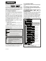
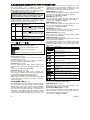
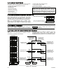
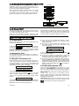
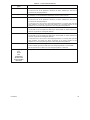
LAN Settings [Fig 4.5.2(9)]
Note: The LAN Settings menu appears only if a Broadband
Module exists in the PowerMaxComplete alarm system.
Enable DHCP [Fig 4.5.2(9a)]
Here you determine whether to obtain an IP address
automatically using a DHCP server or to enter an IP
address manually.
Toggles between DHCP enable and DHCP disable.
Note: When DHCP is enabled, the last IP number will be
changed to 200. In other words, it will take the form
xxx.xxx.xxx.200.
Manual IP [Fig 4.5.2(9b)]
Here you manually enter LAN parameters.
IP address – the IP address of the Broadband Module.
Subnet mask – the subnet mask used with the IP
address.
Default GW – the default gateway of the Broadband Module.
Note: If DHCP is set to enabled the above entries will be
ignored.
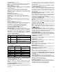
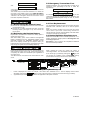
Session Timeout [Fig 4.5.2(10)]
Here you determine whether the control panel will stay
continuously connected via GPRS communication, or,
temporarily connected to receive event reports only.
The options are: off on timeout and always ON.
4.5.3 C.S. Reporting
(Fig. 4.5)
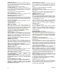
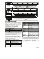
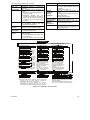
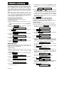
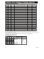
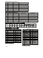
Report Events [Fig 4.5.3(1)] – see note in Fig. 4.5
Here you determine which types of event will be reported
to central stations. Due to lack of space in the display,
abbreviations are used: alarm is “alrm”, alert is “alrt” and
open/close is “o/c”. The asterisk (J) is a separator
between events reported to central station 1 and events
reported to central station 2.
Messages are divided by type into four groups:
No.
1
2
Group
Alarms
Open/close
Events Reported
Fire, Burglary, Panic, Tamper
Arming AWAY, Arming HOME,
Disarming
3
Alerts
No-activity, Emergency, Latchkey,
Gas, Flood, Temperature
4
Maintenance Low-battery AC failure
"Alarm" group has the highest priority and "Alert" group
has the lowest priority.
The selectable options are as follows:
Plan name
Sent to center
Sent to center 2
1
all -o/c J backup All but open/close All but open/close if center 1
doesn’t respond
all J all
All
All
all-o/c J all -o/c
All but open/close All but open/close
all –o/c J o/c
All but open/close Open/close
all (–alrt) J alrt
All but alerts
Alerts
Alrm J all (–alrm) Alarms
All but alarms
Disable report
Nothing
Nothing
all J backup
All
All if cent. 1 doesn’t respond
Note: “All” means that all 4 groups are reported and also
trouble messages - sensor / system low battery, sensor
inactivity, power failure, jamming, communication failure etc.
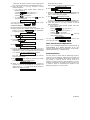
1st Report Method [Fig 4.5.3(2)]
Here you define the 1st priority of method used to report
events.
The options are: disable, cellular, broadband and PSTN.
2nd Report Method [Fig 4.5.3(3)]
Here you define the 2nd priority of method used to report
events. If the method defined to report events in the 1st
D-302754
priority fails, the control panel will attempt to report using
the method defined in the 2nd priority (see notes in 1st
Report Method).
The options are: disable, cellular, broadband and PSTN.
3rd Report Method [Fig 4.5.3(4)]
Here you define the 3rd priority of method used to report
events. If the method defined to report events in the 2nd
priority fails, the control panel will attempt to report using
the method defined in the 3rd priority (see notes in 1st
Report Method).
The options are: disable, cellular, broadband and PSTN.
Dual Reporting [Fig 4.5.3(5)]
Here you determine whether to report events using PSTN
and cellular at the same time instead of waiting for the 1st
method to fail before trying the 2nd method.
The options are: disable, PSTN & broadband, PSTN &
cellular and broadband & cell.
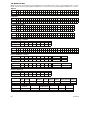
Receiver 1 Account No. [Fig 4.5.3(6)] - see note in
Fig. 4.5
Here you enter the number that will identify your specific
alarm control system to the 1st central station. The number
consists of 6 hexadecimal digits.
Receiver 2 Account No. [Fig 4.5.3(7)] - see note in Fig.
4.5
Here you enter the number that will identify your system to
the 2nd central station. The account number consists of 6
hexadecimal digits.
PSTN/GSM RCVR1 [Fig 4.5.3(8)] - see note in Fig. 4.5
Here you program telephone number of the 1st central station
(including area code, 16 digit max) to which the system will
report the event groups defined in Report Events.
PSTN/GSM RCVR2 [Fig 4.5.3(9)] - see note in Fig. 4.5
Here you program telephone number of the 2nd central station
(including area code, 16 digit max) to which the system will
report the event groups defined in Report Events.
IP RCVR 1 [Fig 4.5.3(10)]
Here you enter the IP address of the IP receiver that is
located in the 1st central station.
IP RCVR 2 [Fig 4.5.3(11)]
Here you enter the IP address of the IP receiver that is
located in the 2nd central station.
SMS RCVR 1 [Fig 4.5.3(12)]
Here you enter the telephone number of the SMS receiver
that is located in the 1st central station.
SMS RCVR 2 [Fig 4.5.3(13)]
Here you enter the telephone number of the SMS receiver
that is located in the 2nd central station.
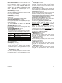
PSTN Report Format [Fig 4.5.3(14)] - see note in Fig.
4.5
Here you select the reporting format used by the control
panel to report events to central stations.
The options are:
SIA text
Contact-ID
SIA
4/2
1900/1400 4/2 1800/2300 Scancom (see Appendix D
- code lists).
4/2 Pulse Rate [Fig 4.5.3(15)] - see note in Fig. 4.5
Here you select the pulse rate at which data will be sent to
central stations if any one of the 4/2 formats has been
selected in PSTN Report Format.
The options are: 10, 20, 33 and 40 pps.
PSTN Report Retry [Fig 4.5.3(16)] - see note in Fig. 4.5
Here you determine the number of times the communicator
will dial the central station’s number via PSTN.
The options are: 2, 4, 8, 12 and 16 attempts.
21