1
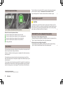
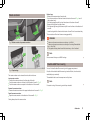
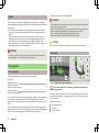
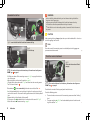
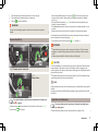
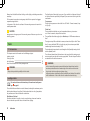
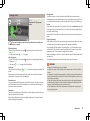
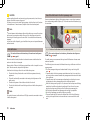
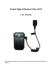
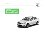
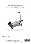
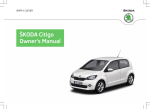
SIMPLY CLEVER www.skoda-auto.com ŠKODA Rapid Addendum Dodatek MR14 Rapid anglicky 05.2013 S56.5612.01.20 5JA 012 025 H The following is displayed in the information display: Addendum Oil change now! Inspection An Inspection is due if the display shows the number 2 at the point marked by the arrow » Fig. 1. Technical changes 05.2013 This supplement replaces the Owner's manual for the Rapid model, Edition 11.2012. The information given in this supplement takes precedence over the information in the Owner's Manual. Service Interval Display The following is displayed in the information display: Inspection in ... km or ... days. As soon as the due date for the service is reached, a flashing key symbol and the text INSPEC_ appears in the display for around 20 seconds after the ignition has been switched on. The following is displayed in the information display: Inspection now! Fig. 1 Service Interval Display: Note Displaying the distance and days until the next service interval You can use button 5 » Owner's Manual, chapter Instrument cluster - Overview to display the remaining distance and days until the next service interval. A key symbol and the remaining distance appear in the display for 10 seconds. At the same time, the days remaining until the next service interval are displayed. In vehicles equipped with the information display, you can call up this display in the Settings menu » Owner's manual, chapter information display. The display can vary depending on the equipment. The following will appear together in the information display for about 10 seconds: Oil change ... km / ... days Before the next service interval is reached, a key symbol and the kilometres and days remaining until the next service is due are shown for about 10 seconds after the ignition is switched on» Fig. 1. The kilometre indicator or the days indicator reduces in steps of 100 km or, where applicable, days until the service due date is reached. Oil change service An oil change service is due if the display shows the number 1 at the point marked by the arrow » Fig. 1. The following is displayed in the information display: Oil change in ... km or ... days. Inspection ... km / ... days Note Information is retained in the Service Interval Display even after the vehicle battery is disconnected. ■ If the instrument cluster is exchanged after a repair, the correct values must be entered in the counter for the Service Interval Display. This work is carried out by a specialist garage. ■ For more information on the service intervals, see » Service schedule, chap ter Service intervals. ■ As soon as the due date for the service is reached, a flashing key symbol and the text OIL CHNG appears in the display for around 20 seconds after the ignition has been switched on. Addendum 1 The force limiter is only switched off if you attempt to close the window again within the next 10 seconds - the window will now close with full force! Electrical power windows If you wait longer than 10 seconds, the force limiter is switched on again. Switch light on and off CAUTION An audible warning signal will sound and the parking light will remain on if the light switch is in the or position, the ignition key is removed and the driver's door is opened. If you are leaving the vehicle and don't want to use the parking light, always turn the light switch to the O position. Fig. 2 Buttons on the driver's door/in the rear doors Buttons for the electrical power windows A Button for electrical power window of the driver's door B Button for electrical power window of the front passenger door C Button for electrical power window of the rear right door D Button for electrical power window of the rear left door S Safety pushbutton DAY LIGHT function (daylight driving lights) Deactivating the function daylight driving lights1) › Deactivate daytime driving lights by removing the fuse for the daytime driving lights » Owner's Manual, chapter Fuses in the electrical panel. Activating the function daylight driving lights1) › Activate daytime driving lights by inserting the fuse for the daytime driving Force limiter The electrical power windows are fitted with a force limiter. It reduces the risk of bruises or injuries when closing the windows. If there is an obstacle, the closing process is stopped and the window opens by a few centimetres. If the obstacle prevents the window from being closed during the next 10 seconds, the closing process is interrupted once again and the window opens by several centimetres. If you attempt to close the window again within 10 seconds of the window being moved down for the second time, even though the obstacle was not yet been removed, the closing process is only stopped. The force limiter is still switched on. 1) 2 Does not apply to vehicles with START-STOP system. Addendum lights » Owner's Manual, chapter Fuses in the electrical panel. Waste container Replace bags › Remove the waste container from the slot. › Push the two catches of the inner frame in direction of arrow 4 » Fig. 4 out of the container body. › Pull the bag together with the inner frame down in direction of arrow 5. › Remove the bag from the inside frame. › Pull the new bag through the frame and pull it over the frame in the direction of arrow 6. › Insert the bag with the frame in the direction of arrow 7 into the container body. The two catches of the inner frame must engage audibly. WARNING Fig. 3 Waste container / open waste container Never use the waste container as an ashtray - risk of fire! Never use the waste container as an ashtray or for storing flammable objects – risk of fire! ■ Only replace the bag when the vehicle is stationary – risk of accident! ■ ■ Note We recommend that you use 20x30 cm bags. Double-sided floor covering Fig. 4 Replace bags The waste container can be inserted into the slots in the doors. Insert waste container › Position the waste container at the front edge of the slot. › Push the waste container to the back in the direction of arrow 1 » Fig. 3. › Push the waste container as required in the direction of the arrow 2. You can fit a double-sided floor covering in the luggage compartment. One side of the double-sided floor covering is made of fabric, the other side is washable (easy to maintain). The washable side is used to transport wet or dirty items. Note For easier turning of the covering, use the loop attached. Remove the waste container › Remove the waste container in the opposite direction to the arrow 1 » Fig. 3. Open/close waste container › Open the waste container in the direction of the arrow 3 » Fig. 3. Closing takes place in the reverse order. Addendum 3 The maximum trailer drawbar load is 50 kg/h. Spoiler WARNING If your new vehicle is fitted with a spoiler on the front bumper in combination with the spoiler on the luggage compartment lid, the following instructions must be adhered to. › For safety reasons, the vehicle must only be fitted with a spoiler on the front bumper in combination with the associated spoiler on the luggage compartment lid. › This kind of spoiler cannot be left on the front bumper either on its own, in combination with another spoiler not on the luggage compartment lid or in combination with an unsuitable spoiler on the luggage compartment lid. › We recommend that you consult the ŠKODA service partner for any repairs to or replacement, addition or removal of spoilers. Check that the ball bar is seated correctly and is secured in the mounting recess before starting any journey. ■ Do not use the ball bar if it is not correctly inserted in the mounting recess. ■ Do not use the towing equipment if it is damaged or incomplete. ■ Do not modify or adapt the towing equipment in any way. ■ Never release the ball bar while the trailer is still coupled. ■ CAUTION Take care with the ball bar to avoid damaging the paintwork on the bumper. WARNING Description If work on your vehicle's spoilers is not carried out properly, this can lead to operational faults - risk of accident and serious injuries. Towing device Introduction This chapter contains information on the following subjects: Description Set stand-by position Assemble the ball bar Check for correct attachment Remove the ball bar Operation and maintenance 4 5 6 6 7 7 If your vehicle has alstand-by position been factory-fitted with towing equipment or is fitted with towing equipment from ŠKODA Original Accessories, then it meets all of the technical requirements and national legal provisions for towing a trailer. Your vehicle is fitted with a 13-pin power socket for the electrical connection between the vehicle and trailer. If the trailer that is to be towed has a 7-pin connector, you can use a suitable adapter from ŠKODA Original Accessories. 4 Addendum Fig. 5 Carrier of the towing device/ball rod First read and observe the introductory information and safety warnon page 4. ings The ball bar can be removed and is kept in the spare wheel well or in a compartment for the spare wheel in the luggage compartment » Owner's manaul, chapter Vehicle tool kit. Explanation of graphic » Fig. 5 1 2 3 13-pin power socket Safety eye Mounting recess 4 5 6 7 8 9 10 11 12 13 14 Cover for the mounting recess Dust cap ball bar Locking ball Centering Green marking on handwheel Handwheel Key Lock cap Red marking on the handwheel White marking on ball bar Fig. 7 Set stand-by position Note On the bottom of the key is a code number. If you lose a key, please contact a specialist garage who will be able to provide you with a new one based on this code number. Set stand-by position First read and observe the introductory information and safety warnings on page 4. Always adjust the ball bar to the stand-by position before fitting. › Turn the key A in the direction of the arrow1 to the stop» Fig. 6. › Hold the ball bar with your left hand. › With the right hand, pull the handwheel B in the direction of the arrow 2 and rotate to the stop in the direction of arrow 3. The hand wheel remains locked in this position. Set stand-by position » Fig. 7 The key C is in the unlocked position - the arrow on the key points to the “padlock open” icon . The key can not be removed. The locking balls D can be pressed completely into the ball bar. The red marking E on the handwheel points to the white marking on the ball bar. There is a gap of about 4 mm F between the handwheel and the ball bar. The adjusted ball bar is ready for insertion into the mounting recess. Fig. 6 Set stand-by position WARNING If the ball bar cannot be correctly adjusted to the stand-by position then it must not be used. CAUTION In the standby position the key cannot be removed from the handwheel lock. Addendum 5 WARNING Assemble the ball bar Do not hold the handwheel with your hand when attaching the ball bar there is a risk of finger injury. ■ After mounting the ball bar always lock the lock and remove the key. ■ The ball bar cannot be operated when the key is inserted. ■ If the ball bar is not in the standby position, it cannot be fixed in the mounting recess. ■ CAUTION After removing the key, always replace the cap on the handwheel lock – there is a risk of dirt getting into the lock. Fig. 8 Insert the ball bar/lock the lock and remove the key Note Store the cover of the mounting recess in a suitable place in the luggage compartment store after removal. Fig. 9 Fit the lock cap Check for correct attachment Fig. 10 Check that the tow bar is fitted properly First read and observe the introductory information and safety warnings on page 4. › Pull the cover down off the mounting recess 4 » Fig. 5 on page 4 in the direction of the arrow . › Adjust the ball bar to the stand-by position» page 5. › Grip the ball bar from underneath » Fig. 8 and insert into the mounting recess until it is heard to latch » . The handwheel A rotates automatically back and rests on the ball rod » › Lock the handweel lock by turning the key . B right as far as the stop in the di- rection of the arrow1 - the arrow on the key points towards the “closed padlock” icon. › Remove the key in the direction of the arrow 2. › Fit the cap on the C handwheel lock in the direction of the arrow 3 » Fig. 9. › Check the tow bar for secure mounting » page 6. 6 Addendum First read and observe the introductory information and safety warnings on page 4. Check that the tow bar is fitted properly each time before use. Check the following points. The tow bar does not come out of the mounting recess even after “shaking” hard. The green marking A » Fig. 10 on the handwheel points to the white mark ing on the ball bar. › Unlock the handweel lock by turning the key The hand wheel now touches the ball bar - there is no gap. The handwheel is locked and the key is removed. The cap B is on the handwheel. WARNING Do not use the towing equipment unless the tow bar has been properly locked. B left as far as the stop in the direction of the arrow2 - the arrow on the key points towards the “padlock open” icon. › Grip the ball bar from below » Fig. 12 and with the other hand pull the handwheel C in arrow direction 3. › The solid handwheel until it stops in the direction of arrow 4 and hold it in this position. › Remove the tow bar in the direction of arrow 5 from the mounting recess. At the same time, the ball bar latches into the stand-by position and is ready to be re-inserted into the mounting recess » . Remove the ball bar › Fit the cover for the mounting recess 4 » Fig. 5 on page 4. WARNING Never allow the tow bar to remain unsecured in the boot. This could cause damage in a sudden braking manoeuvre and put the safety of the occupants at risk. ■ Never release the ball bar while the trailer is still coupled. ■ CAUTION If the handwheel is not turned all the way it will turn back after the ball bar has been removed. It will come to rest on the ball bar and will not engage in the stand-by position. The tow bar then needs to be brought into this position before the next time it is fitted. ■ After dismantling, seal the mounting recess with the cap. This prevents foreign matter from getting into the mounting recess. ■ Fig. 11 Remove cap lock / unlock lock Fig. 12 Release ball bar Note We recommend that you put the protective cap on the ball before removing the ball bar. ■ Clean any dirt from the ball bar before stowing it away in the box with the vehicle tool kit. ■ First read and observe the introductory information and safety warnings on page 4. › Remove the cap › Insert the key B A of the handwheel in the direction of the arrow 1 » Fig. 11. into the lock. Operation and maintenance First read and observe the introductory information and safety warnings on page 4. Close the mounting recess with the cap to prevent any ingress of dirt. Addendum 7 Always check the ball bar before hitching a trailer. Apply a suitable grease where necessary. The distribution of the weight is very poor if your vehicle is unladen and the trailer is laden. Maintain a particularly low speed if you cannot avoid driving with this combination. Fit the protective cap when stowing away the ball bar to protect the luggage compartment against dirt. Tyre pressure Correct the tire pressure on the vehicle for a “full load” » Owner's manual, chapter Tyre life. In the event of dirt, clean the surfaces of the mounting recess and treat with a suitable preservative. Trailer load The permissible trailer load must not be exceeded under any circumstances » Owner's manual, chapter Technical data. CAUTION Apply grease to the upper part of the mounting recess. Make sure you do not remove any grease. The engine output falls as altitude increases, as does the ability to climb. Therefore, for every additional 1000 m in height (or part), the maximum permissible towed weight must be reduced by 10 %. Trailer Introduction The towed weight comprises the actual weights of the (loaded) towing vehicle and the (loaded) trailer. This chapter contains information on the following subjects: Loading a trailer Towing a trailer Anti-theft alarm Use of the child seat in the front passenger seat The trailer and drawbar load information on the type plate of the towing equipment are merely test data for the towing equipment. The vehicle-specific values are detailed in the vehicle documents. 8 9 10 10 WARNING Always drive particularly carefully with the trailer. Loading a trailer First read and observe the introductory information and safety warnings on page 8. The vehicle/trailer combination must be balanced, whereby the maximum permissible drawbar load must be utilised. If the drawbar load is too low, it jeopardises the performance of the vehicle/trailer combination. Distribution of the load Distribute the load in the trailer in such a way that heavy items are located as close to the axle as possible. Secure the items from slipping. 8 Addendum Do not exceed the maximum permissible axle and drawbar load and the maximum permissible total or towed weight of the vehicle and the trailer – there is the risk of an accident and serious injury. ■ Slipping loads can significantly affect the stability and safety of the vehicle/ trailer combination – there is the risk of an accident and serious injury. ■ WARNING The specified trailer loads apply only to altitudes up to 1 000 metres above sea level. Driving speed For safety reasons, do not drive faster than 80 km/h when towing a trailer. Towing a trailer Fig. 13 Swivel out the 13-pin power socket Immediately reduce your speed as soon as even the slightest swaying of the trailer is detected. Never attempt to stop the trailer from “swaying” by accelerating. Brakes Apply the brakes in good time! If the trailer is fitted with a trailer brake, apply the brakes gently at first, then brake firmly. This will avoid brake jolts resulting from the trailer wheels locking. On downhill sections shift down a gear in good time to also use the engine as a brake. First read and observe the introductory information and safety warnings on page 8. Before the journey › Grip the 13-pin socket on the handle A and swing out in the direction of arrow» Fig. 13. › Lift off protective cap 5 » Fig. 5 on page 4. After the journey › Grip the 13-pin socket on the handle A and swing in the opposite direction to the arrow» Fig. 13. › Place the cap 5 » Fig. 5 on page 4 on the ball head. Safety eye The purpose of the safety eye B » Fig. 13 is to attach the breakaway cable of the trailer. When attaching the breakaway cable to the safety eye, in all trailer positions (sharp bends, in reverse, etc.) it must sagfreely. Exterior mirrors You have to have additional exterior mirrors fitted if you are not able to see the traffic behind the trailer with the standard rear-view mirrors. National legal requirements must be observed. Headlights The front of the vehicle can be lifted when a trailer is being towed and the headlights can dazzle other road users. Engine overheating If the needle for the coolant temperature gauge moves into the right-hand area or the red area of the scale, the speed must be reduced immediately. Stop and switch off the engine if the warning light in the instrument cluster starts to flash. Wait a few minutes and check the level of coolant in the coolant expansion bottle » Owner's manual, chapter Check coolant. Read the following instructions » Owner's Manual, chapter Coolant temperature / coolant level. The coolant temperature can be reduced by switching on the heating. WARNING Never use the safety eye to tow a vehicle! Adapt your speed to the conditions of the road surface and to the traffic situation. ■ Improper or incorrectly connected electric cables can energise the trailer and cause functional faults to the vehicle's entire electrical system as well as accidents and severe injuries. ■ Work on the electrical system must only be carried out by specialist garages. ■ Never directly connect the trailer's electrical system with the electrical connections for the tail lights or other current sources. ■ The handbrake on the towing vehicle must be applied when coupling and uncoupling the trailer. ■ ■ Adjust the headlight setting on the headlight range control » Owner's manual, chapter Headlight range control. Addendum 9 CAUTION Use of the child seat in the front passenger seat After coupling the trailer and connecting up the power socket, check the rear lights on the trailer to ensure they work. ■ If there is an error in the trailer lighting system, check the fuses in the fuse box in the dashboard » Owner's manual, chapter Fuses in the electrical panel. ■ Never use a backwards-facing child restraint system on a seat that is protected by an active airbag installed in front of it. This could cause the child severe injury or even death. Note Contact between the breakaway cable and the safety eye can result in mechanical wear on the protective surface of the eye. Such wear does not impair the functioning of the safety eye and is not a fault. It is excluded from the warranty coverage. ■ If you tow a trailer frequently, you should also have your car inspected between service intervals. ■ Fig. 14 Sticker on the B column on the front passenger side. Anti-theft alarm First read and observe the introductory information and safety warnon page 8. ings First read and observe the introductory information and safety warnings on page 8. When the vehicle is locked, the alarm is activated as soon as the electrical connection to the trailer is interrupted. For safety reasons, we recommend that you install child seats on the rear seats whenever possible. Always switch off the anti-theft alarm system before a trailer is coupled or uncoupled » Owner's manual, chapter Anti-theft alarm. The following instructions must be followed when using a child seat on the front passenger seat. › The front passenger airbag must be deactivated if using a rear-facing child seat » . › If possible, adjust the front passenger seat backrest so that it is as vertical, so as to ensure secure contact between the passenger seat backrest and the back of the child seat. › If possible, move the front passenger seat backwards so that there is no contact between the front passenger seat and the child seat behind it. › With child safety seats in groups 2 or 3, make sure that the loop-around fittings attached to the child seat headrest is positioned in front of or at the same height as the loop-around fittings on the B pillar on the passenger side. › Set the height-adjustable front passenger seat as high up as possible. › Set the front passenger seat belt as high up as possible. › Place and fasten the child seat on the seat and the child in the child seat according to the specifications in the manufacturer's user manual of the child seat . Conditions for including a trailer in the anti-theft alarm system. The vehicle is factory-fitted with an anti-theft alarm system and towing equipment. The trailer is electrically connected to the towing vehicle by means of the trailer socket. The electrical system of the vehicle and trailer is functional. The vehicle is locked with the vehicle key and the anti-theft alarm system is activated. Note For technical reasons, trailers with rear LED lights cannot be connected to the anti-theft alarm system. 10 Addendum WARNING The front passenger airbag must be deactivated if using a rear-facing child seat on the front passenger seat » Owners manual, chapter Airbag system. ■ Never use a rear-facing child seat on the front passenger seat if the passenger airbag is activated. This child safety seat is positioned in the deployment area of the front passenger airbag. The airbag may cause the child severe, or even fatal injuries, in the event of it being deployed. ■ This is also clearly stated on the sticker which is located on the B column on the front passenger side » Fig. 14. The sticker is visible upon opening the front passenger door. In some countries, the sticker is affixed to the front passenger sun visor. ■ With child safety seats in groups 2 or 3, make sure that the loop-around fittings attached to the child seat headrest is positioned in front of or at the same height as the loop-around fittings on the B pillar on the passenger side. ■ As soon as the rear-facing child seat is no longer being used on the passenger seat, the front passenger airbag should be re-activated again. ■ Addendum 11 ŠKODA AUTO a.s. pursues a policy of constant product and model development. We trust that you will understand that changes to models in terms of shape, equipment and engineering, may be introduced at any time. The information about appearance, performances, dimensions, weight, standards and functions of the vehicle is correct at the time of publication. Some equipment might only be introduced at a later date, or might only be offered in certain markets; information is provided by ŠKODA Partners. It is therefore not possible for legal claims to be made based on the data, illustrations and descriptions contained in this Owner's Manual. Reprinting, reproduction, translation, or any other use, either in whole or in part, is not permitted without the written consent of ŠKODA AUTO a.s.. ŠKODA AUTO a.s. expressly reserves all rights relating to copyright laws. Subject to change. Issued by: ŠKODA AUTO a.s. © ŠKODA AUTO a.s. 2013 SIMPLY CLEVER www.skoda-auto.com ŠKODA Rapid Addendum Dodatek MR14 Rapid anglicky 05.2013 S56.5612.01.20 5JA 012 025 H