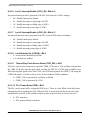
1
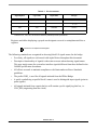
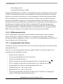
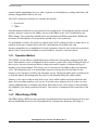
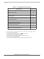
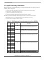
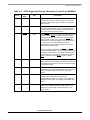
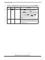
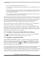
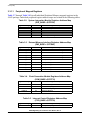
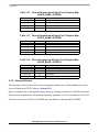
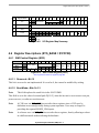
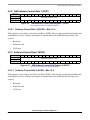
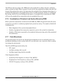
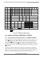
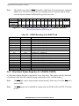
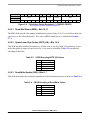
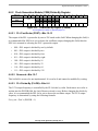
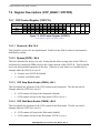
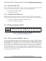
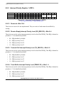
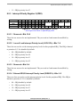
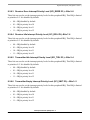
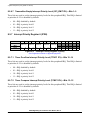
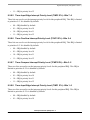
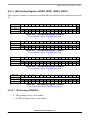
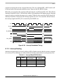
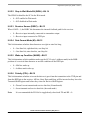
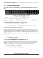
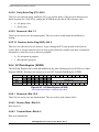
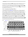
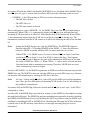
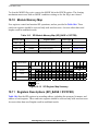
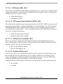
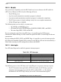
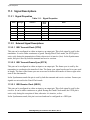
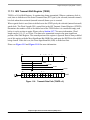
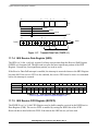
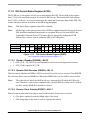
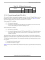
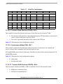
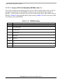
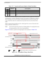
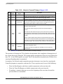
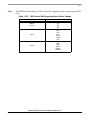
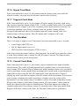
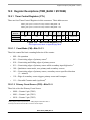
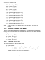
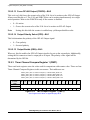
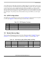
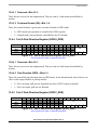
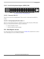
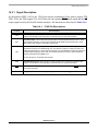
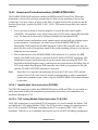
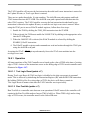
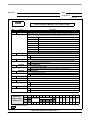
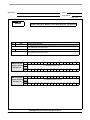
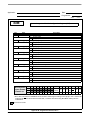
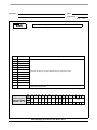
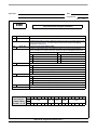
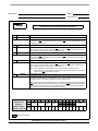
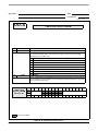
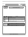
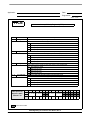
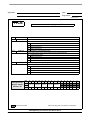
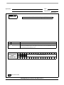
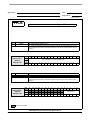
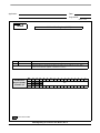
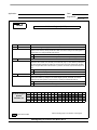
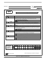
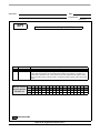
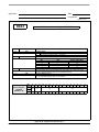
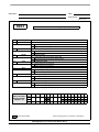
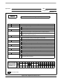
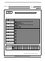
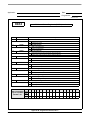
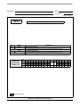
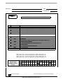
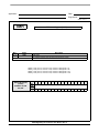
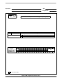
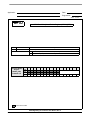
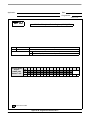
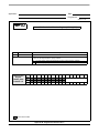
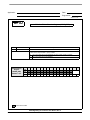
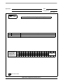
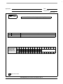
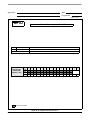
Registers Descriptions (SPI_BASE = $1FFFE8)
10.11.1 SPI Status and Control Register (SPSCR)
The SPSCR register:
•
Enables SPI module interrupt requests
•
Selects interrupt requests
•
Configures the SPI module as Master or Slave
•
Selects serial clock polarity and phase
•
Enables the SPI module Receive Data Register full
•
Fails to clear SPRF bit before next full length data is received (overflow error)
•
Has inconsistent logic level on SS pin (mode fault error)
•
Transmits Data Register Empty
•
Selects Master SPI baud rate
Base + $0
15
Read
13
SPR
Write
Reset
14
0
1
12
11
10
9
8
7
6
5
4
DSO ERRIE MODFEN SPRIE SPMSTR CPOL CPHA SPE SPTIE
1
0
0
0
0
1
0
1
0
0
3
2
1
0
SPRF OVRF MODF SPTE
0
0
0
0
Figure 10-13. SPI Status and Control Register (SPSCR)
See Programmer’s Sheets on Appendix page B-49
Note:
Using BFCLR or BFSET instructions to modify SPSCR can cause unintended side
effects on the status bits.
10.11.1.1 SPI Baud Rate Select Bits (SPR)—Bits 15–13
While in the Master mode, these read/write bits select one of eight baud rates depicted in Table
10-4. SPR2:0 have no effect in Slave mode. Reset clears SPR2:0 to b011. Use the formula below
to calculate the SPI baud rate.
SPR1 and SPR0 have no effect in Slave mode. Reset clears SPR1 and SPR0. Use the formula
below to calculate the SPI baud rate.
Baud Rate = CLK
BD
CLK =Peripheral Bus Clock BD = Baud Rate Divisor
Serial Peripheral Interface (SPI), Rev. 4
Freescale Semiconductor
10-21