1
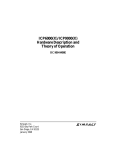
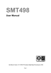
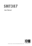
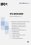
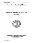
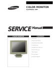
SMT407
User Manual
User Manual; Version 1.0.2, 4/8/04; © Sundance Digital Signal Processing, Inc. 2004
Version 1.0.0
Page 2 of 38
SMT407 User Manual
Revision History
Date
Comments
Engineer
Version
2/28/05
First released version
PTM
1.0.0
Version 1.0.0
Page 3 of 38
SMT407 User Manual
Table of Contents
Revision History ....................................................................................................... 2
Table of Contents ..................................................................................................... 3
Table of Figures........................................................................................................ 6
Table of Tables ......................................................................................................... 6
Physical Properties .................................................................................................. 7
Introduction............................................................................................................... 8
Related Documents ................................................................................................ 8
Block Diagram .......................................................................................................... 8
Mechanical Interface: PMC Standard...................................................................... 9
SMT407 Support ....................................................................................................... 9
SMT407 Installation .................................................................................................. 9
QL5064 .................................................................................................................... 11
Local bus............................................................................................................... 11
Virtex FPGA configuration..................................................................................... 11
Virtex FPGA design .............................................................................................. 12
TI JTAG controller ................................................................................................. 12
TMS320C6416T ....................................................................................................... 13
Boot Mode............................................................................................................. 13
EMIF Control Registers......................................................................................... 13
SDRAM ................................................................................................................. 14
FLASH .................................................................................................................. 14
Virtex FPGA .......................................................................................................... 15
FPGA ....................................................................................................................... 17
Configuration......................................................................................................... 17
JTAG/Boundary Scan........................................................................................ 17
Configuring with MultiLINX ................................................................................ 18
SHBs..................................................................................................................... 19
SHB Connectors................................................................................................ 19
SHB Cable Assembly ........................................................................................ 20
SHB Inter Modules solutions ............................................................................. 20
Half Word Interface (16-bit SHB Interface) ........................................................ 20
Version 1.0.0
Page 4 of 38
SMT407 User Manual
Constraint File Signal Names ............................................................................ 21
RSLs ..................................................................................................................... 22
RSL Connector.................................................................................................. 22
RSL Cable Assembly......................................................................................... 23
RSL Interface .................................................................................................... 23
Local bus............................................................................................................... 23
Clocks ................................................................................................................... 23
Miscellaneous I/O ................................................................................................. 24
Power Supplies ..................................................................................................... 25
DC/DC converter ............................................................................................... 26
Linear Voltage regulator .................................................................................... 26
Power Consumption.............................................................................................. 27
FPDP ........................................................................................................................ 28
Further details ....................................................................................................... 28
Software .................................................................................................................. 28
Further details ....................................................................................................... 28
Verification Procedures ......................................................................................... 29
Review Procedures ................................................................................................ 29
Validation Procedures............................................................................................ 29
FPGA Constraint File General Information........................................................... 29
Ordering Information.............................................................................................. 29
FPGA-only ............................................................................................................ 29
With DSPs............................................................................................................. 29
Custom.................................................................................................................. 30
FPGA................................................................................................................. 30
Memories........................................................................................................... 30
DSPs ................................................................................................................. 30
SHBs ................................................................................................................. 30
RSLs.................................................................................................................. 30
PCB Layout Details ................................................................................................ 31
Components placement ........................................................................................ 31
Headers Pinout ....................................................................................................... 33
SHB Headers ........................................................................................................ 33
Version 1.0.0
Page 5 of 38
SMT407 User Manual
SHB Pinout (LVTTL only) (J3,JA3) .................................................................... 33
RSL Header .......................................................................................................... 34
RSL Side 1 Pinout (LVDS only) (J2).................................................................. 34
RSL Side 2 Pinout (LVDS only) (JA4) ............................................................... 34
JTAG/Multilinx headers ......................................................................................... 35
JTAG Boundary scan pinout (J4) ...................................................................... 35
PMC Pn4 Header .................................................................................................. 36
PMC Pn4 Pinout (LVTTL only) (P14)................................................................. 36
Safety....................................................................................................................... 38
EMC ......................................................................................................................... 38
Version 1.0.0
Page 6 of 38
SMT407 User Manual
Table of Figures
Figure 1: SMT407 Block Diagram............................................................................... 8
Figure 2: Single-size PMC card (from IEEE 1386-2001) ............................................ 9
Figure 3: QL5064 connection ................................................................................... 11
Figure 4: Flash logical sections ................................................................................ 15
Figure 5: JTAG Chain on the SMT407 ..................................................................... 18
Figure 6: SHB Connector.......................................................................................... 19
Figure 7: RSL Top Connector................................................................................... 22
Figure 8: RSL Bottom Connector.............................................................................. 22
Figure 9: FPDP daughter card.................................................................................. 28
Figure 10: SMT407 Components placement-Top view............................................. 31
Figure 11: SMT407 Components placement-Bottom view ....................................... 31
Figure 12: Location of JTAG/Multilinx header........................................................... 35
Figure 13: Top View IEEE 1386 Board-to-Board Plug.............................................. 36
Table of Tables
Table 1: FPGA Choices ............................................................................................ 17
Table 2: RSL Speed vs. FPGA Speed Grade........................................................... 23
Table 3: LED Identification........................................................................................ 25
Table 4: Powering the devices.................................................................................. 25
Table 5: Power Consumption ................................................................................... 27
Table 6: SHB interfaces table ................................................................................... 33
Table 7: RSL Side 1 interface table .......................................................................... 34
Table 8: RSL Side 2 interface table .......................................................................... 34
Table 9: JTAG Connector pinout .............................................................................. 35
Version 1.0.0
Page 7 of 38
SMT407 User Manual
Physical Properties
Dimensions
Single-sized PMC form factor
Weight
TBD g (FPGA only)
TBD g (with DSPs)
TBD g (with DSPs and daughter module)
Supply Voltages
See Power Supplies section
Supply Current
See Power Supplies section
Version 1.0.0
Page 8 of 38
SMT407 User Manual
Introduction
Related Documents
[1] PCI Mezzanine Card (PMC) Spec – IEEE.
http://shop.ieee.org/store/product.asp?prodno=SS94922
[2] Sundance High-speed Bus (SHB) specifications – Sundance.
http://sundance.com/docs/SHB%20Technical%20Specification.pdf
[3] Front Panel Data Port Spec – VITA.
http://www.fpdp.com
[4] External Interface User Manual – Sundance.
http://sundance.com/docs/Firmware.pdf
[5] Rocket Serial Link (RSL) specifications – Sundance.
http://sundance.com/docs/RSL%20%20Technical%20Specification%20Rev01%20Iss03.pdf
[6] Processor PMC (PrPMC) Spec – VITA.
http://www.vita.com/
Block Diagram
HPI/McBSP
EMIFB
R
S
L
S
H
B
DSPA
EMIFA
PCI
Bridge
Virtex II Pro
EMIFA
R
S
L
Flash
SDRAM
S
H
B
DSPB
SDRAM
PMC
P14
HPI/McBSP
Figure 1: SMT407 Block Diagram
PCI
PCI
Host
Version 1.0.0
Page 9 of 38
SMT407 User Manual
Mechanical Interface: PMC Standard
This module conforms to the PMC standard (PCI Mezzanine Card, See Related
Documents.) for single width modules.
It requires a PMC carrier board.
The carrier board provides power, ground, and a PCI bus between the module and
host, for a non stand-alone system.
Figure 2: Single-size PMC card (from IEEE 1386-2001)
SMT407 Support
The SMT407 is supported by the SMT6041-407 software package available from
SUNDANCE. Please register on the SUNDANCE Support Forum if not yet registered.
Then enter your company’s forum and you can request the SMT6041-407 from there.
SMT407 Installation
Do NOT connect any external TTL (5v) signals to the SMT407 I/Os which
connect directly to the FPGA as the FPGA is NOT 5v tolerant. This implies that
the lines on connector P14 of the carrier board MUST be LVTTL and that any
device driving signals on the SHB connectors must drive at LVTTL (3.3v).
You can fit the SMT407 on its own on any PMC compatible carrier board. When
mated with a carrier board such as Twin Industries Xtend1000, it may then be
plugged into a host computer (e.g. Windows PC).
Please, follow these steps to install the SMT407 module on a Host system:
1. Remove the carrier board from the host system.
2. Connect the SHB and/or RSL cable(s) to the top side of SMT407 (if required
by your application).
Version 1.0.0
Page 10 of 38
SMT407 User Manual
3. Place the SMT407 module on a PMC site. (See your carrier board User
Manual.)Make sure that the board is firmly seated before screwing the
SMT407 to the two main mounting holes. Use 10mm M3 Standoffs(Digikey
4391K-ND)and M3 5mm bolts(Digikey H742-ND)to secure the module to any
carrier card.
4. Connect the SHB and/or RSL cables to the back side of the SMT407 (if
required by your application).
5. Replace the carrier board in the host system or power on for a stand-alone
carrier.
Version 1.0.0
Page 11 of 38
SMT407 User Manual
QL5064
The QuickLogic PCI bridge is installed on all configurations of SMT407.
This device combines a 66MHz/64-bit PCI Master/Target ASIC core with a one-time
programmable (OTP) FPGA fabric.
The configuration of the FPGA fabric in the QL5064 is performed prior to
manufacturing of the module and can not be changed by the user.
Local bus
QL5064 provides a bridge between the PCI bus of the host system and the Local bus
of the SMT407. There are three primary functions of the Local bus on SMT407:
1) Configuration of the Virtex FPGA
2) Communication with logic designs loaded in the Virtex FPGA
3) Communication with DSPs over JTAG (applies to DSP boards only)
CS[3:0]
CS[1]
66MHz/
64-bit
QL5064
50MHz/
64-bit
Local bus
PCI bus
16-bit
TI JTAG controller
(DSP boards only)
CS[0]
8-bit
Virtex FPGA config
CS[3:2]
64-bit
Virtex FPGA design
Figure 3: QL5064 connection
More information about the Local bus interface and protocols can be obtained from
QuickLogic at: http://www.quicklogic.com/images/QL5064_CD_UM.pdf
Virtex FPGA configuration
Programming of the Virtex FPGA can be achieved over the PCI bus using the
SelectMAP interface. This interface is 8-bits wide and runs at the full speed of the
Local bus. By simply writing a stream of configuration bytes to the location at CS[0]
the FPGA can be programmed.
An example of this is provided in the SMT6041-407 software package available from
SUNDANCE.
Version 1.0.0
Page 12 of 38
SMT407 User Manual
Virtex FPGA design
Once the FPGA has been programmed the user may then communicate with the
design by means of CS regions 2 and 3. 12 address lines allow for a total
addressable space of 4kB per CS region. Accesses to these regions may be up to
64-bits wide.
An example of this is provided in the SMT6041-407 software package available from
SUNDANCE.
TI JTAG controller
For DSP boards the Texas Instruments SN74ACT8990 is installed. This Test Bus
Controller (TBC) provides XDS510 compatible performance.
Special driver software is required to operate this device. Please contact
SUNDANCE for more information.
Version 1.0.0
Page 13 of 38
SMT407 User Manual
TMS320C6416T
This section applies only to modules built with DSPs.
The processors will run with zero wait states from internal SRAM.
An on-board 50MHz crystal oscillator provides the clock used for the C60s which
then multiply this by 20 to achieve 1GHz internally.
Boot Mode
The SMT407 is configured to boot from Flash only after a reset.
Flash boot:
1. DSPA copies a bootstrap program from the first part of the flash memory into
internal program RAM starting at address 0.
2. Execution starts at address 0.
The standard bootstrap supplied with the SMT407 then performs the following
operations:
1. All relevant C60 internal registers are set to default values;
2. The FPGA is configured from data held in flash memory (DSPA only) and sets
up the communication ports, the global bus and the Sundance High-speed
Buses. This step must have been completed before data can be sent to the
Comports from external sources such as the host or other PMCs;
3. The same boot code is copied to DSPB over HPI and it repeats step 1.
4. A C4x-style boot loader is executed on DSPA and DSPB. This will continually
examine the communication ports until data appears on one of them. The
bootstrap will then load a program in boot format from that port; the loader will
not read data arriving on other ports.
5. Finally, control is passed to the loaded program.
The delay between the release of the board reset and the FPGA configuration is
around TBD s for a SMT407 (1GHz clock).
A typical time to wait after releasing the board reset should be in excess of this delay,
but no damage will result if any of the I/Os are used before they are fully configured.
In fact, the comm. Ports will just produce a not ready signal when data transfer is
attempted during this time, and then continue normally after the FPGA is configured.
EMIF Control Registers
The C6416 has two external memory interfaces (EMIFs). One of these is 64 bits
wide, the other 16 bits.
Version 1.0.0
Page 14 of 38
SMT407 User Manual
The C60 contains several registers that control the external memory interfaces
(EMIFs). A full description of these registers can be found in the C60 Peripherals
Reference Guide.
The standard bootstrap will initialise these registers to use the following resources:
Resource
Memory
space
Address range
(EMIFA)
Internal
(1MB)
program
memory 0x00000000 - 0x000FFFFF
CE0
SDRAM (2x 8MB chips)
0x80000000 - 0x807FFFFF
CE3
Virtex
0xB0000000 - 0xBFFFFFFF
Entries in the following table apply to DSPA only!
Resource
Memory
space
Address range
(EMIFB)
CE0
DSB HPI
0x60000000 – 0x601FFFFF
CE1
1st / 3rd section of flash (2MB
each)
0x64000000 – 0x641FFFFF
CE2
2nd / 4th section of flash (2MB
each)
0x68000000 – 0x681FFFFF
SDRAM
Memory space CE0 is used to access 16MB of SDRAM over EMIFA. The SDRAM
operates with a max frequency of 133MHz. The speed of this interface is determined
by a clock oscillator on the board. This speed adjustment is not a user option, but
must be adjusted during manufacture.
The EMIFA CE0 memory space control register should be programmed with the
value 0x00000030.
Note that the DSP only has 20 address pins on the EMIFA, but since address bits are
multiplexed for SDRAM a maximum addressable space of 128MB is possible.
FLASH
An 8MB Flash ROM device is connected to the C60 EMIFB.
Version 1.0.0
Page 15 of 38
SMT407 User Manual
The ROM holds boot code for the C60, configuration data for the FPGA, and optional
user-defined code.
The EMIFB CE1 and CE2 space control registers should be programmed with the
value 0xFFFFFF03.
As the C60 only provides 20 address lines on its EMIFB, both CE1 & CE2 are used
to access this device. This in itself allows the direct access of 4MB. A paging
mechanism is used to select which half of the 8MB device is visible in this 4MB
window.
As the EMIFB CE1 & 2 memory spaces alias throughout the available range, the
flash device can be accessed using the address range 0x67E00000-0x681FFFFF.
This gives a 4MB continuous space.
The flash can be divided into the four logical sections shown in the following figure
(paging bit is bit 21).
0x67C00000
Page0
(2 MBytes)
CE0
Section 1
0x67E00000
Page1
(2 MBytes)
Section 2
0x68000000
Page0
(2 MBytes)
CE1
Section 3
0x68200000
Page1
(2 MBytes)
Section 4
0x68400000
Figure 4: Flash logical sections
To change the state of the page bit, you need to write to the following address as
shown (the data written are irrelevant):
Address
Flash page selected
0x6C000000
Page 0 (1st and 3rd
sections enabled)
0x6C000001
Page 1 (2nd and 4th
sections enabled)
The EMIFB CE0 space control register should be programmed with the value
0xFFF0C003.
Virtex FPGA
The SMT407 incorporates a Xilinx Virtex II Pro XC2VP50 FPGA (XC2VP20,
XC2VP30, and XC2VP40 are also possible). This device controls the majority of the
I/O functionality on the module, including the Comports, SHBs, timers and interrupts.
Version 1.0.0
Page 16 of 38
SMT407 User Manual
This device requires configuring after power-up (the Virtex technology is an SRAM
based logic array). This configuration is performed by the DSP as part of the boot
process.
Two control register bits are needed for this purpose, one to put the FPGA into a
‘waiting for configuration’ state, and another to actually transfer the configuration
data.
The PROG pin (causes the FPGA to enter the non-configured state) is accessed at
address 0x6C02000X. Writing to address 0x6C020000 will assert this pin, and
address 0x6C0200001 will de-assert this pin.
The configuration data clock is accessed at address 0x6C080001. Each bit of the
FPGA’s configuration bit-stream must be serially clocked through this address.
Note: This configuration process is part of the standard boot code, and does not
need to be implemented in any user application.
Version 1.0.0
Page 17 of 38
SMT407 User Manual
FPGA
The module can be fitted with an XC2VP20, XC2VP30, XC2VP40, or XC2VP50
FPGA.
Only flip-chip FF1152 package will fit on this board.
The choice of FPGA will be price/performance driven. The following table shows the
main FPGA characteristics.
The choice of the FPGA also determines which board architecture you will get
(amount of logic available, speed, number and type of I/Os, on-board Memory size
and type). For a complete list of the different board architectures, please consult:
Ordering Information
This Xilinx Virtex II Pro, is responsible for the provision of two SHBs, 4 internal
Comports (2 per DSP), a PCI Local bus interface, and 24 RSLs (In FULL
configuration, see Ordering Information).
CLB(1 CLB = 4 slices =
Max 128 bits)
Device
RocketIO
Transceiver
Blocks
PowerPC
Processor
Blocks
XC2VP20
8
XC2VP30
SelectRAM Blocks
Slices
Maximum
distributed
RAM Kbits
Multiplier
blocks
20,880
9,280
290
2
30,816
13,696
12
2
43,632
16
2
53,136
Logic
Cells
2
8
XC2VP40
XC2VP50
18-Kbit
Block
Max RAM
(Kbits)
DCMs
88
88
1,584
8
428
136
136
2,448
8
19,392
606
192
192
3,456
8
23,616
738
232
232
4,176
8
Table 1: FPGA Choices
Configuration
The FPGA can be configured 3 different ways:
•
Loading the FPGA from flash on the board using DSPA.
•
Using SMT6041-407 to load the FPGA over the PCI bus.
•
Using the on-board JTAG header and Xilinx JTAG programming tools.
JTAG/Boundary Scan
The JTAG Programmer software is a standard feature of the Alliance Series ™ and
Foundation Series ™ software packages. JTAG Programmer is a part of Web Pack,
which can be downloaded from the following site:
Xilinx JTAG programmer
The JTAG chain is composed only of the FPGA.
Version 1.0.0
Page 18 of 38
SMT407 User Manual
Figure 5: JTAG Chain on the SMT407
Xilinx describes how to connect both download cables at: Parallel cables
Xilinx describes how to configure their devices using these cables at: Configuration
Mode General Information.
For complementary and more detailed information please go to: Xilinx 5 software
Manuals and Help.
See board header pinout in Table 9: JTAG
Configuring with MultiLINX
The Mutilinx cable can be used to configure the FPGA via JTAG.
See board header pinout in Table 9: JTAG.
The MultiLINX cable set is a peripheral hardware product from Xilinx.
For additional information on the MultiLINX cable set, go to the following site:
Xilinx MultiLINX cable
Using MultiLINX /Parallel cable III or IV
The JTAG header is provided to enable device programming via suitable software.
Typically, this will be Xilinx iMPACT.
Xilinx iMPACT supports both the Xilinx MultiLINX™ and Parallel Cable III download
cables for communication between the PC and FPGA(s). The MultiLINX cable
supports both USB (Windows 98 and Windows 2000) and RS-232 serial
communication from the PC. The Parallel Cable III supports only parallel port
communication from the PC to the Boundary Scan chain.
The JTAG header on the board was designed to mate directly with the 2mm
ribbon cable provided with the MultiLINX Cable IV. BE SURE TO ATTACH
THE RIBBON CABLE WITH THE ALIGNMENT PIN FACING AWAY FROM
THE BOARD!
Version 1.0.0
Page 19 of 38
SMT407 User Manual
SHBs
SHB Connectors
The SMT407 includes two 60-pin connectors to provide SHB communication to the
outside world.
The connector is referenced on the PCB by J3 and JA3 (See Figure 10: SMT407
Components placement-Top view and See Figure 11: SMT407 Components
placement-Bottom view).
All 60 pins of each SHB connector are routed to the FPGA in all available
configurations of SMT407.
Pin2
Pin 1
r
ral G
Integ
5m
0.
m
d
e an
Blad
De
Beam
ound
e
plan
sign
nt
nme
Al i g
Pi n
Figure 6: SHB Connector
Features:
High-speed socket strip: QSH-030-01-L-D-A-K on the SMT407, mates with
QTH-030-01-L-D-A-K
QTH are used for cable assembly or PCB connecting 2 PMCs.
Centreline: 0.5mm (0.0197”)
QSH Connector
An adapter is available for Agilent probes for the 16760A Logic Analyser.
The 2 probes supported are the E5378A 100-pin Single-ended Probe and the
E5386A Half Channel Adapter with E5378A.
Version 1.0.0
Page 20 of 38
SMT407 User Manual
SHB Cable Assembly
The cable is custom made by Precision Interconnect and a cable assembly solution
builder can be found at: http://www.precisionint.com/tdibrsb/content/howtouse.asp
SHB Inter Modules solutions
High-speed data transfer can be achieved between PMC modules thanks to the use
of a 60-way flat ribbon micro-coax cable or via PCB connections.
As a result, NO DIFFERENTIAL lines are required to transfer data on long distances
and at speeds in excess of 100MHz, which allows the full use of the SHB connector
60 pins.
Half Word Interface (16-bit SHB Interface)
The SHB connectors provide to the FPGA connections to the external world.
You can implement your own interface to transfer data over using these connectors,
but if you want to communicate with other Sundance modules, you can implement a
Half Word (Hw) interface sitting on 25 pins of an SHB connector.
Then, the SHBs are parallel communication links for synchronous transmission.
An SHB interface is derived from the SDB interface which is a 16-bit wide
synchronous communication interface. (SUNDANCE SDB specification)
The differences are:
The SHB interface can be made Byte (8 bits), Half Word (16 bits) or
Word (32 bits) wide.
The transfer rate can be increased thanks to better quality interconnect.
As an example, let us consider the Half Word (Hw) SHB interface.
You can implement 2 x 16-bit SHB interfaces per SHB connector, and have some
spare signals for User defined functions. (no differential lines are needed thanks to
our SHB cable assembly described in SHB Cable Assembly).
The SMT407 provides two SHB connectors and can support data rates of 400MB/s
at 100MHz on each of these interfaces.
You must refer to the latest SUNDANCE SDB specification for technical information
on how it works.
Version 1.0.0
Page 21 of 38
SMT407 User Manual
Constraint File Signal Names
According to the SUNDANCE SHB specification, 5 Byte-interfaces (from 0 to 4) can
be implemented on the 60 pins of a SHB connector. Each Byte interface has its own
CLK, WEN, REQ and ACK.
The signal names going from the FPGA to the SHB connector use the configuration
of 2 SDB interfaces.
So, when in Half Word configuration:
•
16-bit data D(0 to 15)
•
CLK0 is borrowed from Byte configuration 0, WEN1, REQ1 and ACK1 are
borrowed from Byte configuration 1 to make configuration SDBA control
signals and
•
CLK3 is borrowed from Byte configuration 3, WEN4, REQ4 ACK4 are
borrowed from Byte configuration 4 to make configuration SDBB control
signals.
The SHB connectors are J3 and JA3. (See Figure 10: SMT407 Components placementTop view and See Figure 11: SMT407 Components placement-Bottom view)
Please refer to section SHB Headers for more information.
Version 1.0.0
Page 22 of 38
SMT407 User Manual
RSLs
RSL Connector
The SMT407 includes two 28-pin (14-pair) RSL connectors.
The connectors are referenced on the PCB by J2 and JA4 (See Figure 10: SMT407
Components placement-Top view and Figure 11: SMT407 Components placementBottom view).
24 pins (12 pairs) of each RSL connector (48 total) are routed to the FPGA in all
available configurations of SMT407.
Figure 7: RSL Top Connector
Figure 8: RSL Bottom Connector
Features:
High-speed socket strip: QSE-014-xx-DP on the SMT407 Side 1, mates with
QTE-014-xx-DP
High-speed socket strip: QTE-014-xx-DP on the SMT407 Side 2, mates with
QSE-014-xx-DP
Samtec for details
Version 1.0.0
Page 23 of 38
SMT407 User Manual
RSL Cable Assembly
Cable assemblies with QTE connectors on one side and QSE on the other are like
the flexible versions of the PCB adapters mentioned above.
RSL Interface
The RSL connectors are the fastest FPGA connections available on SMT407.
As RSL are based on RocketIO transceiver blocks, the speed is limited by the speed
grade of FPGA installed:
Speed grade
RSL speed (Gbps)
-7
-6
-5
3.125
3.125
2.0
Table 2: RSL Speed vs. FPGA Speed Grade
Based on the above, the 12 bi-directional links of SMT407 can provide a combined
bandwidth of up to 37.5Gbps.
The RSL connectors are J2 and JA4. (See Figure 10: SMT407 Components placementTop view and See Figure 11: SMT407 Components placement-Bottom view)
The RSL connector on the front of the board (J2) is of type “RSL Top”. The RSL
connector on the back of the board (JA4) is of type “RSL Bottom”.
Refer to the latest SUNDANCE RSL specification for technical information on how it
works.
Local bus
http://www.quicklogic.com/images/QL5064_CD_UM.pdf
Clocks
The FPGA is provided with the following clocks:
Description
Speed
DSPA EMIFA clock
100MHz*
DSPB EMIFA clock
100MHz*
QL5064 Local bus clock
50MHz
RSL LVDS clock
125MHz
* Standard only on DSP modules. TI specs allow this clock to go as high as 133MHz,
but keep in mind that this clock will also be used for the SDRAM.
Version 1.0.0
Page 24 of 38
SMT407 User Manual
Miscellaneous I/O
There are four LEDs connected directly to the FPGA and four additional LEDs
connected directly to the DSPs (2 each). For DSP modules the software interface to
the LEDs connected to the FPGA is located in the LED register of the standard
Sundance firmware. Bits 0 and 1 of the LED register control the LEDs designated to
the respective DSP. See Table 5 for details on LED identification.
Version 1.0.0
Page 25 of 38
LED Designator
Meaning
D4
Board reset
D5
DSPA LED0 (GP0)
D6
DSPA LED1 (GP1)
D7
DSPB LED0 (GP0)
D8
DSPB LED1 (GP1)
D9
FPGA LED0
D10
FPGA LED1
D11
FPGA LED2
D12
FPGA LED3
D13
FPGA DONE
SMT407 User Manual
Table 3: LED Identification
See Figure 10: SMT407 Components placement-Top view.
Power Supplies
Due to the close packing of components between PMC Side 1 and the host module,
power consumption is limited to 4.0W for 10.0mm standoffs (this increases to 6.0W
for 13.0mm standoffs). The total consumption for Side 1 and Side 2 of the module
shall not exceed 7.5W, and represents the total power drawn from all power rails
provided at the connector (+5V, +3.3v, +VI/O, +12V,-12V, +3.3Vaux).
For this reason it is recommended that you analyse the total FPGA device power
drawn by using Xilinx XPOWER before implementing your design in the FPGA.
TI 6416 DSP
FPGA
XC2VP
QuickLogic SDRAM
5064
RSL
Vccint/Vdd
1.2v
1.5v
3.3v
3.3v
N/A
Vcco/Vddq
3.3v
3.3v
3.3v/5v
3.3v
N/A
Vrioa
N/A
2.5v
N/A
N/A
2.5v
Vriob
N/A
2.5v
N/A
N/A
2.5v
Vccaux
N/A
2.5v
N/A
N/A
N/A
Table 4: Powering the devices.
DC/DC
converter
PCI 3.3v
Version 1.0.0
Page 26 of 38
SMT407 User Manual
PCI VIO
Voltage
regulator
This module must have 5V and 3.3V supplied through the PMC connectors. Either
5V or 3.3V may be supplied for PCI I/O voltage and should be consistent with the
signalling standard of the PCI host bus. +12V and -12V are optional and may be
supplied to the PMC connectors as per PMC specifications.
Contained on the module are linear regulators for the FPGA VCCAUX and FPGA
RocketIO. A DC/DC converter supplies the core voltage for the FPGA and DSPs.
DC/DC converter
An International Rectifier IP1201 Power Block is used to supply the 1.5V core voltage
to the FPGA and 1.2V core voltage of the DSPs. The current limits are configured for
10A and 5A, respectively. The DC/DC converter is powered from the 5V supply.
Linear Voltage regulator
The FPGA VCCAUX and FPGA RocketIO voltages are supplied through linear
voltage regulators drawn from 3.3V.
Version 1.0.0
Page 27 of 38
SMT407 User Manual
Power Consumption
Measurements were made on an SMT407 at idle with the standard FPGA
configuration loaded. Requirements will vary depending on software activity, FPGA
configuration, environment, and other factors.
Supply (V)
Current (A)
Power (W)
3.3
TBD
TBD
5.0
TBD
TBD
Total
-
TBD
Table 5: Power Consumption
Note: Figures do not include power required for the carrier board itself.
FPGA: Depending on the implemented design, the power consumption can reach 30
Watts or more. Please consider connecting an external power supply to the carrier
board for demanding designs.
Version 1.0.0
Page 28 of 38
SMT407 User Manual
FPDP
Figure 9: FPDP daughter card
Further details
TBD
Software
Further details
Please consult the documentation included with the SMT6041-407 package for
details on the internals of this software.
Version 1.0.0
Page 29 of 38
SMT407 User Manual
Verification Procedures
The specification (design requirements) will be tested using the following:
1) Power module test.
2) FPGA configuration using PCI and/or JTAG connector.
3) SDRAM memory tests.
4) SHB connector Pins Test using SHB tester PCBs.
5) PCI transfers between host and SMT407 FPGA.
Only for DSP boards:
Comport transfers between a host and the SMT407.
Review Procedures
Reviews will be carried out as indicated in design quality document QCF14 and in
accordance with Sundance’s ISO9000 procedures.
Validation Procedures
The validation procedure is happening during the verification procedure.
Test that all the memories are accessible by the FPGA as well as all the
communication links.
FPGA Constraint File General Information
Since only the FF1152 package type is supported on SMT407, one constraints file is
provided.
Ordering Information
Currently, the SMT407 is available in 2 configurations: FPGA-only and With DSPs.
FPGA-only
In the basic configuration a Virtex II Pro 50 is used and allows interfacing to ALL the
memories and ALL I/Os available on the SMT407. Two banks of 16MB of SDRAM
are installed attached to the FPGA.
With DSPs
This configuration includes everything in the FPGA-only variant with the addition of
two TI 6416T DSPs.
Version 1.0.0
Page 30 of 38
SMT407 User Manual
Custom
The ordering code for custom configuration is as follows:
SMT407–VP50-5-x-D
Board Type
Virtex II part
Virtex II speed grade
On-board SDRAM in MB
With DSPs
FPGA
Part options: VP20, 30, 40, 50
Speed grades: 5, 6, 7
Memories
SDRAM (per bank/DSP): 16MB, 32MB, 64MB, 128MB
DSPs
Two Texas Instruments 1GHz 6416T DSPs
SHBs
One SHB connector is available in all configurations to allow the
implementation of up to 2x16-bit SDB interfaces.
A second SHB may be fitted to the back of the board if strict PMC compliance
is not necessary.
RSLs
One RSL connector is available in all configurations to allow the
implementation of up to 12 RSL interfaces.
A second RSL connector may be fitted to the back of the board if strict PMC
compliance is not necessary.
Version 1.0.0
Page 31 of 38
PCB Layout Details
Components placement
Figure 10: SMT407 Components placement-Top view
Figure 11: SMT407 Components placement-Bottom view
U14: Xilinx FPGA
U18: QuickLogic
U6: TI 6416T (DSPA)
U4: TI 6416T (DSPB)
U5 & U23: DSPA SDRAM
SMT407 User Manual
Version 1.0.0
Page 32 of 38
U3 & U22: DSPB SDRAM
U24: Flash
U8: Xilinx FPGA and DSP Core Power Supply
U1 & U20: RSL Power Supplies
U17: VCCAUX Power Supply
Y2: EMIF External Clock (100MHz)
Y3: DSP Core / 20 and Local bus Clock (50MHz)
Y4: RSL LVDS Clock (125MHz)
SMT407 User Manual
Version 1.0.0
Page 33 of 38
SMT407 User Manual
Headers Pinout
SHB Headers
Headers are per SUNDANCE SHB specification Half Word configuration.
QSH Pin number
QSH Pin number
Hw
SHBxCLK0
1
2
SHBxD0(0)
SHBxD0(1)
3
4
SHBxD0(2)
SHBxD0(3)
5
6
SHBxD0(4)
SHBxD0(5)
7
8
SHBxD0(6)
SHBxD0(7)
9
10
SHBxD0(8)
SHBxD0(9)
11
12
SHBxD0(10)
SHBxD0(11)
13
14
SHBxD0(13)
15
16
SHBxD0(14)
SHBxD0(15)
17
18
SHBxUSER0(16)
SHBxUSER0(17)
19
20
SHBxUSER0(18)
SHBxUSER0(19)
21
22
SHBxWEN1
SHBxREQ1
23
24
SHBxACK1
SHBxUSER1(23)
25
26
SHBxUSER1(24)
SHBxUSER1(25)
27
28
SHBxUSER1(26)
SHBxUSER1(27)
29
30
SHBxUSER1(28)
SHBxUSER1(29)
31
32
SHBxUSER1(30)
SHBxUSER1(31)
33
34
SHBxUSER1(32)
SHBxUSER1(33)
35
36
SHBxUSER1(34)
SHBxCLK3
37
38
SHBxD1(0)
SHBxD1(1)
39
40
SHBxD1(2)
SHBxD1(3)
41
42
SHBxD1(4)
SHBxD1(5)
43
44
SHBxD1(6)
SHBxD1(7)
45
46
SHBxD1(8)
SHBxD1(9)
47
48
SHBxD1(10)
SHBxD1(11)
49
50
SHBxD1(13)
51
52
SHBxD1(14)
SHBxD1(15)
53
54
SHBxUSER2(52)
SHBxUSER2(53)
55
56
SHBxUSER2(54)
SHBxUSER2(55)
57
58
SHBxWEN4
SHBxREQ4
59
60
SHBxACK4
Table 6: SHB interfaces table
Hw0
Hw
Hw1
Hw1
Hw0
SHB Pinout (LVTTL only) (J3,JA3)
SHBxD0(12)
SHBxD1(12)
Version 1.0.0
Page 34 of 38
RSL Header
Headers are per RSL Spec.
RSL Side 1 Pinout (LVDS only) (J2)
Pin #
Function
Function
Pin #
1
TXAP0
RXAP0
2
3
TXAN0
RXAN0
4
5
TXAP1
RXAP1
6
7
TXAN1
RXAN1
8
9
TXAP2
RXAP2
10
11
TXAN2
RXAN2
12
13
TXAP3
RXAP3
14
15
TXAN3
RXAN3
16
17
TXAP4
RXAP4
18
19
TXAN4
RXAN4
20
21
TXAP5
RXAP5
22
23
TXAN5
RXAN5
24
25
Reserved
Reserved
26
27
Reserved
Reserved
28
Table 7: RSL Side 1 interface table
RSL Side 2 Pinout (LVDS only) (JA4)
Pin #
Function
Function
Pin #
1
RXBP0
TXBP0
2
3
RXBN0
TXBN0
4
5
RXBP1
TXBP1
6
7
RXBN1
TXBN1
8
9
RXBP2
TXBP2
10
11
RXBN2
TXBN2
12
13
RXBP3
TXBP3
14
15
RXBN3
TXBN3
16
17
RXBP4
TXBP4
18
19
RXBN4
TXBN4
20
21
RXBP5
TXBP5
22
23
RXBN5
TXBN5
24
25
Reserved
Reserved
26
27
Reserved
Reserved
28
Table 8: RSL Side 2 interface table
SMT407 User Manual
Version 1.0.0
Page 35 of 38
SMT407 User Manual
JTAG/Multilinx headers
Figure 12: Location of JTAG/Multilinx header
JTAG Boundary scan pinout (J4)
The JTAG/Multilinx header has the following pinout:
Name
Pin
Function
Connections
VCC
2
Power.
To target system
VCC
Supplies VCC (3.3V, 10 mA, typically) to the cable.
TMS
4
Test Mode Select.
This signal is decoded by the TAP controller to control test operations.
TCK
6
Test Clock.
This clock drives the test logic for all devices on boundary-scan chain.
TDO
8
Read Data.
Read back data from the target system is read at this pin.
TDI
10
Test Data In.
This signal is used to transmit serial test instructions and data.
GND
NC
1, 3,
5, 7,
9,
11,
13
Ground.
12,
14
No connection
Supplies ground reference to the cable.
Table 9: JTAG Connector pinout
Connect to system
TMS pin.
Connect to system
TCK pin.
Connect to system
TDO pin.
Connect to system
TDI pin.
To target system
ground
Not connected
Version 1.0.0
Page 36 of 38
PMC Pn4 Header
Figure 13: Top View IEEE 1386 Board-to-Board Plug
PMC Pn4 Pinout (LVTTL only) (P14)
Pin #
FPGA pin
FPGA pin
Pin #
1
AJ18*
AF11
2
3
AE19
AJ21
4
5
AK21
AM22
6
7
AM21
AF19
8
9
AG10
AG19
10
11
AH10
AH20
12
13
AK8
AJ20
14
15
AL8
AL21
16
17
AE13
AL20
18
19
AF13
AD18
20
21
AG13
AE18
22
23
AH13
AH19
24
25
AJ11
AJ19
26
27
AK11
AK19
28
29
AE14
AL19
30
31
AF14
AF18
32
33
AJ13
AG18
34
35
AK13
AM13
36
37
AL11
AF16
38
39
AM11
AG16
40
41
AE15
AH15
42
43
AF15
AJ15
44
45
AG14
AL14
46
47
AH14
AL15
48
SMT407 User Manual
Version 1.0.0
Page 37 of 38
49
AL13
AD17
50
51
AL12
AE17
52
53
AD16
AH16
54
55
AE16
AJ16
56
57
AJ14
AK16
58
59
AK14
AL16
60
61
AM14
AF17
62
62
AG17
AJ17*
64
* Global clock inputs
SMT407 User Manual
Version 1.0.0
Page 38 of 38
SMT407 User Manual
Safety
This module presents no hazard to the user.
EMC
This module is designed to operate from within an enclosed host system, which is
build to provide EMC shielding. Operation within the EU EMC guidelines is not
guaranteed unless it is installed within an adequate host system.