1
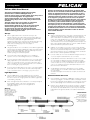
PELICAN
Catalog #9500
Pelican 9500 User Manual
The Pelican 9500 Shelter Lighting System (SLS)
contains three red/white LED light heads, a
universal power supply, an inline switch, fixing straps and a
series of connecting cables. The light heads
can be linked together as per the diagram and secured
with the fixing straps inside a temporary shelter/accommodation.
The light output color (red or white) is selected via
the inline switch and each light head can be
independently switched on or off via the push button
switch on the light head end cap. The system can
be powered by the enclosed universal AC power
supply or by an auxiliary 12-30vdc power source via the
enclosed auxiliary power cable.
™
Sistema de alumbrado de marquesinas de Pelican 9500
dispone de tres cabezales luminosos LED rojo/blanco, una
fuente de alimentación universal, un interruptor en línea,
correas de fijación y una serie de cables de conexión. Los
cabezales luminosos pueden encajarse como se muestra
en el diagrama y asegurarse con las correas de fijación
dentro de un alojamiento temporal. El color (rojo o blanco)
de salida de la luz se seleccionapor medio del interruptor en línea y cada cabezal luminoso puede apagarse o
encenderse de manera independiente a través del botón
interruptor que hay en el extremo del cabezal luminoso. El
sistema puede alimentarse con la fuente de alimentación
de CA universal incluida o con una fuente de alimentación
auxiliar de CC de 12-30 V utilizando el cable de alimentación auxiliar incluido.
Set up:
1. Remove light heads from the case and fix securely to the
Montaje:
1.Saque los cabezales luminosos de la caja y colóquelos fijamente en la
2.
sing the two Green color coded cables, connect all three light heads
U
together as per the diagram. Spiralling the cables around the shelter/
accommodation frame will help to keep the cables tidy and secure.
Make sure the visible LED’s inside the light
head are pointing in a downwards position.
2.Utilizando los dos cables de color verde, conecte los tres cabezales
3.
onnect the in-line switch output cable (color coded Green)
C
up to the connector on the first light head (color coded Green).
4.
If you are using AC voltage as the power source, connect the power
supply output cable (color coded Yellow) to the inline switch input
cable (color coded Yellow). Then connect the mains power cable
(color coded Red) to the power supply input lead (color coded Red)
before connecting into your power source.
5.
If you are using 12-30vdc as the power source, connect the auxiliary
power cable (color coded Yellow) to the in-line switch input cable
(color coded Yellow) before connecting to your power source.
internal shelter/accommodation frame using the fixing straps (one
each end of the light head) – do not space the light heads further
than 4 meters (12 ft) apart. The light heads have an
input and an output end so ensure they are all facing the same way
with the push button switch towards the inline rocker switch.
Fit the enclosed sealing cap on the end (output) of
the last light head.
Light Operation:
1.Once the 9500 SLS is correctly installed, the user can switch
between ‘red’, ‘off’ or ‘white light’ via the inline switch. The ‘off’ selection can be used as an emergency ‘black out’ if all three light heads
need switching off quickly.
2.
ach of the light heads can be switched on or off independently via
E
the push button switch on the end of each light head
(while still maintaining power to the next light head) if
less light is required.
Warning:
Do not connect more
than three light heads
together at any one time.
If more light heads are
required, use an
additional 9500
SLS independently.
estructura del alojamiento interno utilizando las correas de fijación
(una en cada extremo del cabezal). No deje un espacio superior a 4
metros entre cada cabezal luminoso. Los cabezales luminosos tienen
un extremo de entrada y otro de salida; asegúrese de colocar todos
en la misma dirección con el botón interruptor hacia el interruptor oscilante en línea. Ajustar la tapa incluída en el extremo (salida) del último
sistema de iluminación para sellar el cabezal.
luminosos como muestra el diagrama. Colocando los cables en espiral
alrededor de la estructura del alojamiento, los mantendrá ordenados
y bien sujetos. Asegúrese de que los LED visibles dentro del cabezal
luminoso estén colocados apuntando hacia abajo.
3.Conecte el cable (de color verde) de salida del interruptor en línea en
el conector del primer cabezal luminoso (de color verde).
4.Si está utilizando una fuente de alimentación de CA, conecte el cable
(de color amarillo) de salida de la fuente de alimentación al cable
(de color amarillo) de entrada del interruptor en línea. A continuación,
conecte el cable (de color rojo) de alimentación de red al cable (de
color rojo) de entrada de la fuente de alimentación antes de conectarlo a su fuente de alimentación.
5.Si está utilizando una fuente de alimentación de CC de 12-30 V,
conecte el cable (de color amarillo) de alimentación auxiliar al cable
(de color amarillo)
de entrada del interruptor en línea antes de conectarlo a su fuente de alimentación.
Funcionamiento de la luz:
1.Una vez instalado correctamente el 9500 SLS, el usuario podrá elegir
entre ‘luz roja’, ‘apagado’ o ‘luz blanca’ mediante el interruptor en línea.
La selección de ‘apagado’ puede utilizarse como ‘apagón’ de emergencia si necesitara apagar los tres cabezales luminosos rápidamente.
2.Cada uno de los cabezales luminosos puede encenderse o apagarse
de manera independiente por medio del botón interruptor que hay
en el extremo de cada cabezal luminoso (a la vez que se mantendría
la alimentación del siguiente cabezal) si necesitase una iluminación
menor.
Advertencia:
No conecte más de
tres cabezales
luminosos al mismo
tiempo. Si necesita más
cabezales luminosos,
utilice otro 9500
SLS independiente
Pelican 9500
Le système d’éclairage pour abri Pelican 9500 comporte
trois têtes d’éclairage LED rouges/blanches, une source
d’alimentation universelle, un interrupteur de ligne, des arcs de
fixation et une série de câbles de connexion. Les têtes d’éclairage
peuvent être reliées entre elles comme indiqué sur le diagramme
et fixées à l’aide des arcs de fixation à l’intérieur d’un abri/logement temporaire. La couleur d’éclairage en sortie (rouge ou
blanche) est sélectionnée à l’aide de l’interrupteur de ligne et
chaque tête d’éclairage peut être indépendamment mise sous ou
hors tension via l’interrupteur-poussoir situé sur le capuchon à
l’extrémité de la tête. Le système peut être alimenté par la source
d’alimentation CA universelle intégrée ou via une source
d’alimentation CC de 12-30 V auxiliaire grâce au câble
d’alimentation auxiliaire inclus.
Installation :
1. Retirez les têtes d’éclairage du boîtier et fixez-les fermement au cadre de l’abri/
du logement interne à l’aide des arcs de fixation (à chaque extrémité de la tête).
Ne placez pas les têtes d’éclairage à plus de 4 mètres l’une de l’autre. Les têtes
d’éclairage comportent une extrémité d’entrée et une autre de sortie, afin de
garantir qu’elles sont toutes dirigées dans le même sens avec l’interrupteurpoussoir vers l’interrupteur de ligne à bascule. Fixer le capuchon d’étanchéité
fourni à l’extrémité (en sortie) de la dernière tête d’éclairage.
2.
l’aide des deux câbles de code couleur vert, raccordez les trois têtes
À
d’éclairage entre elles comme indiqué sur le diagramme. En enroulant les
câbles en spirale autour du cadre de l’abri/du logement, vous êtes sûr qu’ils ne
s’emmêleront pas et qu’ils resteront correctement branchés. Veillez à ce que les
LED visibles à l’intérieur de la tête d’éclairage soient orientées vers le bas.
3.Raccordez le câble de sortie de l’interrupteur de ligne (code couleur vert)
au connecteur de la première tête d’éclairage (code couleur vert).
4.Si vous utilisez une tension CA comme source d’alimentation,
5.
raccordez le câble de sortie d’alimentation (code couleur jaune) au câble
d’entrée de l’interrupteur de ligne (code couleur jaune). Raccordez ensuite
le câble d’alimentation secteur (code couleur rouge) au fil d’entrée
d’alimentation (code couleur rouge) avant de le brancher à la source
d’alimentation.
Si vous utilisez une source d’alimentation CC de 12-30 V, raccordez le
câble d’alimentation auxiliaire (code couleur jaune) au câble d’entrée
de l’interrupteur de ligne (code couleur jaune) avant de le brancher à la
source d’alimentation.
Fonctionnement de la torche :
1.Une fois le système 9500 SLS correctement installé, l’utilisateur peut
faire basculer l’éclairage entre rouge, hors tension et lumière blanche
grâce à l’interrupteur de ligne. La position hors tension peut être
utilisée comme système d’extinction totale d’urgence lorsque les
trois têtes d’éclairage doivent être rapidement mises hors tension.
2.Chacune des têtes peut être indépendamment mise sous ou hors tension
à l’aide de l’interrupteur-poussoir situé à son extrémité (tout en conservant la tête d’éclairage voisine allumée) s’il est requis moins de lumière.
AVERTISSEMENT :
Ne connectez pas simultanément entre elles plus de trois têtes d’éclairage.
Si vous avez besoin de plus de trois têtes, utilisez indépendamment un
autre système 9500 SLS.
REMOTE AREA LIGHTING SYSTEMS
PELICAN 1 YEAR LIMITED WARRANTY FOR RALS PRODUCTS
Pelican Products, Inc. (“Pelican”) warrants to the original purchaser its Remote Area Lighting Systems (RALS) and all other products manufactured by the Advanced Area Lighting Group
(AALG) against defects in materials and workmanship under normal use, service, and maintenance for a period of twelve months from the date of purchase. This warranty applies only to
the original purchaser and is not transferable.
TO THE EXTENT PERMITTED BY LAW: (A) THIS WARRANTY IS IN LIEU OF ALL WARRANTIES, EXPRESS OR IMPLIED, INCLUDING, BUT NOT LIMITED TO, THE IMPLIED
WARRANTIES OF MERCHANTABILITY AND FITNESS FOR A PARTICULAR PURPOSE; AND (B) ALL OTHER IMPLIED WARRANTIES AND ANY LIABILITY NOT BASED
UPON CONTRACT ARE HEREBY DISCLAIMED AND EXCLUDED.
TO THE EXTENT PERMITTED BY LAW, IN NO EVENT SHALL PELICAN BE LIABLE FOR ANY INDIRECT, PUNITIVE, INCIDENTAL OR CONSEQUENTIAL DAMAGES, OR
SPECIAL DAMAGES, REGARDLESS OF WHETHER A CLAIM FOR SUCH DAMAGES IS BASED ON WARRANTY, CONTRACT, NEGLIGENCE OR OTHERWISE. To the extent
permitted by law, in no event shall Pelican’s liability to the purchaser for damages hereunder exceed the purchase price of the product in respect of which damages are claimed.
With valid dated proof of purchase, Pelican will either repair or replace ay defective part, at our sole option. TO THE EXTENT PERMITTED BY LAW, THE REMEDIES HEREBY PROVIDED SHALL BE THE SOLE AND EXCLUSIVE REMEDIES OF THE ORIGINAL PURCHASER. Any repaired or replacement part or unit is covered only for the unexpired portion of
the warranty on the original product purchased.
To make a warranty claim, the purchaser must contact Pelican Products, Inc. at 23215 Early Avenue, Torrance, CA 90505 or [email protected], or by calling 1-800-473-5422,
extension 5. Any warranty claims shall be made by the purchaser as soon as practicable and in no event more than twelve months from the date of purchase. The purchaser must provide
valid dated proof of purchase and obtain a return authorization number from Pelican Customer Service prior to returning any product, and is responsible for paying for all warranty freight
costs. If Pelican determines that any returned product is not defective, within the terms of this warranty, the purchaser shall pay Pelican all costs of handling, return freight and repairs at
Pelican’s prevailing rates.
All warranty claims of any nature are barred if the product has been altered or in any way physically changed, or subjected to abuse, misuse, negligence or accident.
Some states and countries do not allow limitations on how long an implied warranty lasts or the exclusion or limitation of incidental or consequential damages, so the above limitation or
exclusion may not apply to you. This warranty gives you specific legal rights, and you may have other rights which vary from state to state and country to country.
In Australia: The benefits provided to you under this warranty are in addition to your rights and remedies as a consumer under the Competition and Consumer Act 2010 (Cth). Nothing
in this warranty limits the rights or obligations of a party under provisions of the Competition and Consumer Act 2010 (Cth) in relation to the supply to consumers of goods which cannot be
limited, modified or excluded. If applicable, our goods come with guarantees that cannot be excluded under the Australian Consumer Law. You are entitled to a replacement or refund for
a major failure and compensation for any other reasonably foreseeable loss or damage. You are also entitled to have the goods repaired or replaced if the goods fail to be of acceptable
quality and the failure does not amount to a major failure. If you are not a consumer under the Competition and Consumer Act 2010 (Cth), then your rights may be limited. To make a
warranty claim, the purchaser must contact Pelican Products Australia, Suite 2.33, West Wing, Platinum Bldg., Erina NSW 2250, Tel: +612 4367 7022. Any warranty claims shall be made
by the purchaser as soon as practicable. The purchaser must obtain a return authorization number from Pelican Customer Service prior to returning any product, and is responsible for
paying for all warranty freight costs. If Pelican determines that any returned product is not defective, within the terms of this warranty, the purchaser shall pay Pelican all costs of handling,
return freight and repairs at Pelican’s prevailing rates. In the event that Pelican determines that any returned product is defective, within the terms of this warranty, Pelican shall pay the
purchaser all reasonable costs of the purchaser in making claim under this warranty.
CON LA GARANTÍA LIMITADA DE EXCELENCIA DE POR VIDA DE PELICAN
Pelican Products, Inc., ofrece una garantía de por vida en sus linternas contra roturas o defectos de fabricación. Esta garantía no cubre la lámpara ni las pilas.
Las reclamaciones de garantía de cualquier clase se considerarán nulas en caso de que el producto haya sufrido alteraciones, daños o modificaciones físicas de
cualquier tipo, se haya hecho un uso incorrecto, abusivo o negligente o haya sufrido accidentes. La garantía de por vida no cubre las maletas rotomoldeadas, los
productos del AALG ni la parte de tejido de las mochilas.
GARANTIE D’EXCELLENCE À VIE LIMITÉE DE PELICAN
Pelican Products, Inc. garantit à vie ses torches contre la casse et les défauts de fabrication. Cette garantie ne couvre pas l’ampoule ou les piles. Toute demande de
prise en charge sous garantie, de quelque nature que ce soit, sera refusée si le produit a été transformé, endommagé ou physiquement modifié d’une façon ou d’une
autre, ou encore sujet à un traitement abusif, une mauvaise utilisation, une négligence ou un accident. Pour une version complète et détaillée de la garantie, voir
http://www.pelican.com/warranty.
La garantie à vie ne couvre pas les valises rotomoulées, les produits AALG et la partie en tissu des sacs à dos.
RoHS compliant
PELICAN PRODUCTS
23215 Early Ave. • Torrance, CA 90505 USA • Tel (310) 326-4700 • FAX (310) 326-3311 • www.pelican.com
PELICAN PRODUCTS ULC 10221-184th Street • Edmonton, Alberta T5S 2J4 Canada • Tel (780) 481-6076 • FAX (780) 481-9586 • www.pelican.ca
All trademarks and logos displayed herein are registered and unregistered trademarks of
Pelican Products, Inc. and others.
009503-5411-001 5-12808 © 2014 Pelican Products DE/14