1
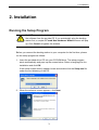
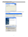
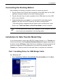
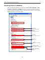
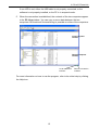
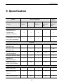
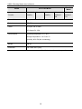
USB 2.0 Docking Station User’s Manual Copyright Statement No part of this publication may be reproduced in any form by any means without the prior written permission. Other trademarks or brand names mentioned herein are trademarks or registered trademarks of their respective companies. Disclaimer Information in this document is subject to change without notice. The manufacturer does not make any representations or warranties (implied or otherwise) regarding the accuracy and completeness of this document and shall in no event be liable for any loss of profit or any commercial damage, including but not limited to special, incidental, consequential, or other damage. June 2005, Rev2.0 i Safety Instructions Always read the safety instructions carefully Keep this User’s Manual for future reference Keep this equipment away from humidity Lay this equipment on a reliable flat surface before setting it up If any of the following situation arises, get the equipment checked by a service technician: • The equipment has been exposed to moisture. • The equipment has been dropped and damaged. • The equipment has obvious sign of breakage. • The equipment has not been working well or you cannot get it work according to User’s Manual. ii Table of Contents 1. Introduction .......................................................................................................1 Features ............................................................................................................................. 1 Package Contents .............................................................................................................. 2 System Requirements........................................................................................................ 2 LED Status ........................................................................................................................ 2 2. Installation .........................................................................................................3 Running the Setup Program .............................................................................................. 3 Connecting the Docking Station ....................................................................................... 5 Installation for Data Transfer Model Only........................................................................ 5 Part 1. Installing Driver for USB Bridge Cable.........................................................................5 Part 2. Installing PC-Linq ..........................................................................................................8 Checking Device Installation .......................................................................................... 10 Self-Power Mode vs Bus-Power Mode........................................................................... 11 3. PC-to-PC Data Link .........................................................................................12 4. Operation Notes About the Ports...................................................................14 5. Specification....................................................................................................15 6. Regulatory Compliance ..................................................................................17 FCC Conditions .............................................................................................................. 17 CE ................................................................................................................................... 17 iii 1. Introduction 1. Introduction This USB 2.0 Docking Station is a unique expansion unit specially designed to accompany notebook or desktop PC, which has extra connectivity demands. With only one USB port required from a notebook/desktop PC, not only USB but also conventional PIO, SIO, LAN, and PS/2 peripheral devices can be accessed freely*. The USB 2.0 Docking Station allows you to add multiple high-performance USB 2.0 peripheral devices to your PC. Moreover, this product is fully backwards compatible with the USB Revision 1.1 products, which means your previous USB 1.1 devices can continue to function as well. You also can add additional hubs and devices of up to 127 devices. Furthermore, with the USB file transfer port*, it provides a direct USB-to-USB data exchange channel between two notebooks/PCs for maximal data portability. To utilize peripherals with no need to turn the PC or notebook inside out for hardware setup and no complex software installation, with the docking station, one can just plug and play all kinds of USB/conventional peripherals at a time without worrying the availability of ports or the need of re-booting the notebook/PC. *The USB 2.0 docking station comes in different specifications; given functions depend on your model. Features Great expansion unit for notebook to other devices Compliant with USB 1.1/2.0 specifications. Maximum transfer rate of 480Mbps. Supports PS/2 keyboard/mouse (optional), IEEE-1284 parallel printer, serial device, USB file transfer (optional) and 10/100Mbps LAN connection (optional). Two or four USB 2.0 downstream ports. Fully compliant with plug & play and hot swapping. Supports self-power and bus-power mode. 1 USB 2.0 Docking Station User’s Manual Package Contents Before installation, please check the items of the package. The package should contain the following items: USB 2.0 Docking Station x1 Power Adapter x1 USB 2.0 Cable x1 Driver CD x1 Quick Installation Guide x1 System Requirements Pentium compatible PC or notebook Windows 2000, Server 2003 and XP USB port CD-ROM drive (for driver installation) LED Status LED Color Description Power Red Lights up when the docking station is powered on. USB Hub Green Lights up when ready to connect to a USB device. Green Lights up if the speed of LAN is 100Mbps. (1-2 or 1-4) LAN 10/100 Off if the speed of LAN is 10Mbps. Link Green LAN activity. Blinking when there is data flow between LAN and the host computer. 2 2. Installation 2. Installation Running the Setup Program Do NOT connect the docking station to your computer before installing the software from the provide CD. If you accidentally plug the docking station first, a couple of Found New Hardware Wizard screens will pop up. Click Cancel to bypass the screens. Before you connect the docking station to your computer for the first time, please run the setup program as follows: 1. Insert the provided driver CD into your CD-ROM drive. The setup program starts automatically and pops up the screen below. Select a language for the installation and click OK. If the setup screen doesn’t appear, locate and double-click the Setup.exe file under the root directory of the CD. 2. When the welcome screen appears, click Next. 3 USB 2.0 Docking Station User’s Manual 3. Click Install to begin the installation. 4. When prompted to plug in the hardware, just click OK. DO NOT plug in the device at this point. 5. Click Finish to complete the installation. 6. If prompted to restart your computer, click Yes. 4 2. Installation Connecting the Docking Station After installing the software, proceed as follows to connect the device: 1. Plug the square end (Type B male receptacle) of the USB cable into the USB upstream connector located on the side of docking station. 2. Plug the flat end (Type A male receptacle) of the USB cable into a free USB port on your computer. 3. (Optional) Plug the power adapter to a household AC outlet and plug the adapter’s DC jack into the DC socket on the side of docking station. *The docking station supports both self-power mode and bus-power mode. Refer to the “Self-Power Mode vs Bus-Power Mode” section for details. For non data-transfer model, your installation is now complete. You can now connect your peripherals to the docking station. Installation for Data Transfer Model Only If your docking station comes with USB File Transfer function (i.e., a Transfer port on the device’s side), the Found New Hardware Wizard will appear searching for the driver for the USB Bridge Cable. After driver installation, the setup program will continue to install the PC-Linq application to be used for file transfer via the Transfer port. Please proceed as instructed below to complete the installation. Part 1. Installing Driver for USB Bridge Cable For Windows XP 1. Select Install the software automatically (Recommended) and click Next. 5 USB 2.0 Docking Station User’s Manual 2. If digital signature message appears, just click Continue Anyway. 3. When the following screen appears, click Finish. For Windows 2000, Server 2003 1. When the Found New Hardware Wizard appears, click Next. 6 2. Installation 2. Select Search for a suitable driver for my device (recommended) and click Next. 3. Select the CD-ROM drives option and click Next. 4. When Windows found the driver, click Next. 7 USB 2.0 Docking Station User’s Manual 5. Click Finish. Part 2. Installing PC-Linq 1. Click Next to install the PC-Linq application. 2. Choose a destination folder for installation or use the defaults. Then click Next. 8 2. Installation 3. Select a program folder where you want the PC-Linq icon to be listed or use the defaults. Then click Next. 4. When the installation is complete, the PC-Linq icon will be added to the desktop. 9 USB 2.0 Docking Station User’s Manual Checking Device Installation Once you finish the installation, you can open Windows Device Manager (via My Computer > Properties > Hardware) to verify if your docking station is properly installed with all the provided functions. There should be a couple of device entries added to the device list as shown below: Keyboard * For PS/2 within model Mouse * For PS/2 within model LAN port * For LAN port within model Serial port USB hub (2 or 4 ports) USB Bridge Cable * For Transfer port within model IEEE-1284 parallel printer 10 2. Installation Self-Power Mode vs Bus-Power Mode Note that there are two modes of powering USB peripherals, self-power mode and bus-power mode. The self-power mode means the peripheral has its own power adapter for operation. Bus-power mode means the peripheral operates under the power from the upstream port that it is connected to. The USB 2.0 docking station can operate under both USB bus-power and self-power mode. However, under bus-power mode, each downstream facing port of the docking station cannot supply current for more than 100mA. Therefore, devices (e.g. USB scanner or multi-function peripheral, MFP) with power demand higher than this value cannot function. In this situation, it is recommended to operate this docking station under self-power mode whenever possible. USB bus-power mode is only for low power consumption devices. 11 USB 2.0 Docking Station User’s Manual 3. PC-to-PC Data Link This chapter is for models with Transfer port only. If your device doesn’t support this function, please ignore this chapter. Using the docking station that comes with USB file transfer function, you can connect two PCs and exchange data between them through the USB ports. For this purpose, you need two computers, each with a USB port, and an additional USB cable (Type A to B, sold separately) for connection. The computer that is connected to the docking station’s upstream facing port acts as a local (master) machine. It can use all the ports on the docking station. The other one is used as the auxiliary (remote) computer for sharing its data storage device. To perform the PC-Linq (file transfer) function: 1. Both local (master) and remote (auxiliary) computers must perform the driver and application installation process as described in the previous chapter. 2. Connect the local and remote computers through the docking station: Local computer: Connected to the docking station’s Upstream (Local) port. Remote computer: Connected to the docking station’s Transfer (Remote) port. 3. Run the PC-Linq program on both computers by double-clicking the PC-Linq icon on the desktop. 4. Wait for the connection to be established. There are two indicators at the bottom right corner of the user interface window showing the connection status. The left one is for the local computer and right one for the remote computer. A red indicator means the connection to that computer is not established, and a green one means the connection to that computer is established. Both LEDs need to be in green color for a proper link and operation. 12 3. PC-to-PC Data Link If one LED is red, either the USB cable is not properly connected, or the software is not properly installed, or the PC is in suspend mode. 5. When the connection is established, the contents of the two computers appear in the PC-Linq window. You can copy or move data between the two computers. Bi-directional file transferring is possible on either of the computers. Local computer window Remote computer window Local connection indicator Remote connection indicator For more information on how to use the program, refer to its online help by clicking the Help icon. 13 USB 2.0 Docking Station User’s Manual 4. Operation Notes About the Ports When connecting peripheral devices to the docking station, pay attention to the following notes: USB Hub Ports: When connecting a USB device to one of the downstream USB ports of the docking station, make sure to follow the software installation manual accompanied (if any) with this USB device. PS/2 Ports (Keyboard and mouse port): Some compatibility issue may occur due to the loosely specified PS/2 protocols and the sheer vast brands/models existing. However, if the PS/2 keyboard or mouse is IBM PC compatible, then it should be able to work with the docking station properly. Serial Port: Note that serial port is not a plug and play interface. If you connect a serial port device (e.g. a modem) to the docking station and the docking station is connected to a PC already, you need to perform the Add New Hardware function from the Control Panel or remove and re-plug the docking station to the PC to find the device and perform the function. USB-to-serial interface: The interface was designed to work with modems or any serial device that has drivers capable of handling “VIRTUAL PORT”. The mice of serial type are old devices and most of their drivers recognize physical serial ports only. Thus, the compatibility of the USB-to-serial interface and the serial mouse is not guaranteed at all. There are rare few cases that it can work, but for the majority of the serial mice, they are not compatible with the USB-to-serial interface. LAN Port: This port supports Ethernet 10/100 Mbps function. 14 5. Specification 5. Specification Function 4-Port Hub Model 2-Port Hub Model Model With LAN & Without LAN Without Without Without Datalinq Datalinq & Datalinq & LAN PS/2 Datalinq USB Port Upstream port for computer side 1 1 1 1 1 2 2 2 2 4 (Type B receptacle) Downstream ports for USB hub (Type A receptacle) I/O Ports PS/2 keyboard port 1 1 1 1 N/A 1 1 1 1 N/A 1 1 N/A N/A N/A Serial port (DB 9 pin male) 1 1 1 1 1 Parallel port 1 1 1 1 1 1 N/A 1 N/A 1 (Mini Din 6 pin) PS/2 mouse port (Mini Din 6 pin) File transfer port (Type B receptacle) (DB 25 pin female) 10/100M LAN port (8P8C RJ 45 shielding) LED Power LED (Red) 1 1 1 1 1 USB Hub Port LED 2 2 2 2 4 2 N/A 2 N/A 2 (Green) LAN Port LED (Green) 15 USB 2.0 Docking Station User’s Manual Function 4-Port Hub Model 2-Port Hub Model Model With LAN & Without LAN Without Without Without Datalinq Datalinq & Datalinq & LAN PS/2 Datalinq Power Mode Bus-powered and Self-powered Emission CE, FCC Power AC Input 100 V~240V DC Output 5V, 2.5A Environments Operating temperature: 0°C~40°C Storage temperature: -10°C~80~°C Humidity: 90% RH (No condensing) Weight 148 (g) Dimension 178 x 58.6 x28.7 (mm) * Specification is subject to change without notice. 16 6. Regulatory Compliance 6. Regulatory Compliance FCC Conditions This equipment has been tested and found to comply with Part 15 of the FCC Rules. Operation is subject to the following two conditions: (1) This device may not cause harmful interference (2) This device must accept any interference received. Including interference that may cause undesired operation. CE This equipment is in compliance with the requirements of the following regulations: EN 55 022: CLASS B 17