1
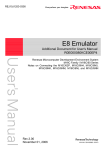
User
Powerful Processors – Easy to Use™
CAN
Development
Kit
Using and Expanding
the RSK CAN Demo
Network
Rev. 2.2
December 2008
www.renesas.com
Table of Contents
1.0 Introduction ............................................................................................................................................. 3
Demos 4
1.1. Summary ........................................................................................................................................... 4
1.2. CAN Bus Termination ........................................................................................................................ 4
1.3. Connecting the Boards ...................................................................................................................... 5
1.4. A-D demo........................................................................................................................................... 5
1.5. PlayCatch Network Test .................................................................................................................... 6
2.0 The RSK-R8C23 Board .......................................................................................................................... 9
2.1. Programming the RSK23................................................................................................................... 9
2.2. Debugging the RSK23 ..................................................................................................................... 12
2.2.1. Simple Demo to Begin Debugging CAN: ‘Just A-D’.................................................................. 14
3.0 The RSK-M16C29 Board...................................................................................................................... 15
3.1. RSK29 Overview ............................................................................................................................. 15
3.1.1. The M16C/29 MCU ................................................................................................................... 15
3.2. Programming the RSK29................................................................................................................. 16
3.3. Debugging the RSK29 ..................................................................................................................... 18
4.0 The RSK-M16C6NK Board................................................................................................................... 21
4.1. RSK Overview ................................................................................................................................. 21
4.1.1. The M16C/6NK MCU ................................................................................................................ 21
4.2. Programming the RSK6NK.............................................................................................................. 22
4.3. Debugging the RSK6NK.................................................................................................................. 24
5.0 The RSK-M32C87 Board...................................................................................................................... 26
5.1. RSK Overview ................................................................................................................................. 26
5.1.1. The M32C/87 MCU ................................................................................................................... 27
5.2. Programming the RSK87................................................................................................................. 28
5.3. Debugging the RSK87 ..................................................................................................................... 29
6.0 The RSK-R32C118 Board .................................................................................................................... 31
6.1. Overview.......................................................................................................................................... 31
6.1.1. The R32C/118 MCU.................................................................................................................. 31
6.2. Connecting to the RSK118 .............................................................................................................. 32
6.3. Programming the RSK118............................................................................................................... 32
6.4. Debugging the RSK-R32C118 ........................................................................................................ 34
7.0 The SysTec CAN Sniffer ...................................................................................................................... 36
Using the RSK Demo CAN Network, Rev 2.2
2/36
Dec 2008
1.0 Introduction
This guide shows how to program, debug and run the standard demo on all CAN MCUs of the
M16C family, the R32C being the latest addition.
The Renesas CAN Demonstration & Development Kit (CAN D Kit) comes with two RSK-R8C23 Renesas
Starter Kit boards, but the demo may be expanded to use any of the following starter kits; the RSKM16C29, the dual-channel RSK-M16C6NK, RSK-M32C87 and RSK-R32C118. Compatible demo code
and cabling exists for all these evaluation boards. The demo is virtually the same for all boards. The RSKM16C6NK, RSK-M32C87, RSK-R32C118 can run two CAN networks simultaneously.
The kits include firmware, a CAN Sniffer and cables and an E8 debugger. The E8 in-system debugger
and programmer also supports all boards except the RSK-R32C118 which needs the E8A.
To get started quickly using a sample project with code for the RSK23 boards that come with the original
kit, open the project file CanDkit.hws from C:\Renesas\RCDK8C\Demo_code\CanDkit-RSK2310bitAD. Program one RSK23 board with the MOT file (see chapter 2.1 Programming the RSK23) and
debug the other board with the same project (see chapter 2.2 Debugging the RSK23).
For LIN, consult the LIN documentation and sample code that comes with the CD install.
Using the RSK Demo CAN Network, Rev 2.2
3/36
Dec 2008
Demos
1.1. Summary
The demonstration projects show the M16C CAN API in use for the Renesas MCUs of the M16C family.
The boards included in your CAN D Kit have already been programmed with software to demonstrate
CAN bus communication, the LCD, the LEDs and pushbuttons, as well as transmit, receive, and timer
interrupts.
The accompanying CAN Demo Kit project contains subprojects for all five aforementioned RSK boards.
Each subproject contains two simultaneously running demos using four mailboxes (slots).
A minimum of two boards must be connected via the CAN bus connectors. Press SW1 to alternate
between ‘PlayCatch’ and 'Streaming-AD' demo programs.
After installing the CAN D Kit CD, go to C:\Renesas\RCDK8C\Demo_code to access the demo source
code.
1.2. CAN Bus Termination
The CAN bus must be terminated at its two outermost ends. Termination resistors are connected on all
RSK boards by default at shipment.
If more than two boards are connected to the CAN bus, only the two boards on the outermost ends of the
bus should be terminated; any boards connected in between should not have any termination. The demo
will still run, but the more nodes are added with termination resistors, the more that value will deviate from
the standard.
On some RSK boards, a jumper can be used to connect or disconnect the termination resistor to the CAN
bus. The termination resistors are connected by default at shipment on all boards, without a termination
selection jumper in place. A 0Ω resistor is installed by default to bypass the jumper. Therefore, if you want
to enable or disable termination by adding this jumper you must first remove the 0Ω resistor that
bypasses the jumper.
The RSK R8C/23
The termination jumper is JP11 and the 0Ω resistor to be removed is R62.
The RSK M16C/29
On the RSK29, the jumper is JP10 and the 0Ω resistor to be removed is R81.
The RSK M16C/6NK
The RSK6NK has no jumpers to enable or disable CAN bus termination. To eliminate CAN bus
termination, remove resistors R132 + R133 for CAN0 and R134 + R135 for CAN1.
The RSK M32C/87
The RSK87 has no jumpers to enable or disable CAN bus termination. However make sure the bus is
terminated at network ends. Also, make sure the board is fitted with the following resistors so it is CAN
enabled:
•
R129. Connects microcontroller pin 90 to CAN0 EN pin.
•
R119. Connects microcontroller pin 89 to CAN0 STBn pin.
•
R66. Connects microcontroller pin 88 to CAN1 EN pin.
•
R46. Connects microcontroller pin 87 to CAN1 STBn pin.
The RSK R32C/118
Using the RSK Demo CAN Network, Rev 2.2
4/36
Dec 2008
The RSK R32C/118 has no jumpers to enable or disable CAN bus termination.
1.3. Connecting the Boards
Connect all the RSKs together onto the CAN bus by connecting the accompanying CAN D Kit red/white
CAN bus cable (or your own CAN bus cable) between the boards — CAN Hi to the red wire and CAN Lo
to the white wire. CAN Hi is marked with an arrow on the CAN connecting jumper.
RSK Board
RSK23
RSK29
RSK6NK
RSK87
RSK R32C118
MCU CAN Interface
CAN0
CAN0
CAN0
CAN1
CAN0
CAN1
CAN0
CAN1
CAN Connection Jumper
J12
J11
J15
J14
J14
J15
Right above transceiver
‘U6’ on the RSK.
Right above transceiver
‘U5’ on the RSK.
Connect a DC 5V supply to each board’s power connector. You can use a power supply for this or use
the E8 programmer/debugger to power up to six boards. See the CAN D Kit User Manual for more
information on supplying power to the boards.
1.4. A-D demo
All RSKs can measure a variable analog voltage that is applied to one of its Analog-to-Digital Converter
(A-D) input pins. When the A-D value is changed by turning the potentiometer on the demo board, it is
transmitted on the CAN bus. If correctly connected to the CAN bus, the transmitting board’s red LED
(LED2) lights up every time an ‘A-D data frame’ is transmitted onto the bus.
Use the workspace CanDkit_23_29_6NK_87_118 to run the demo. To select the RSK you have, in HEW,
select from the menu, Project->Select current Project, then select your RSK.
After downloading the demo as described in the next section, press Switch one to start the A-D demo.
The LCD should display CAN: xx on the first and A-D Rx on the second row. xx is a two-digit hex number
that represents the Analog-to-Digital Converter value received via the CAN bus.
Turn the board’s potentiometer and the conversion value will be sent onto the CAN bus and displayed by
another board configured to receive frames with this message ID. The receiving board must be in
Streaming A-D demo mode to show the received value. (The transmitting board actually does not have to
be in Streaming A-D demo mode — only the receiver.) The receiving board’s green LED0 lights up every
time an ‘A-D data frame’ is received.
View the Receive ID (RXID) for a board by pressing SW3. View the Transmit ID (TXID) by pressing SW2.
Pressing and holding SW2, while at the same time pressing SW3, allows you to change the TXID to
values from 01h to 0Fh. Each push of SW3 increments the TXID by one.
Pressing and holding SW3, while at the same time pressing SW2, allows you to change the RXID to
values from 01h to 0Fh. Each push of SW2 increments the RXID by one.
To be able to receive the transmitted A-D data frame, the receiving board(s) RXID must be identical to the
transmitting board’s TXID.
Using the RSK Demo CAN Network, Rev 2.2
5/36
Dec 2008
The voltage over the potentiometer R9 is A-D converted continuously. When the value changes, it is
transmitted over the CAN bus. Turn the potentiometer on one board and see the value change on the
other board(s). LED2 (red) blinks with every CAN interrupt as A-D data frames are transmitted over the
bus. It indicates that you have a valid CAN bus connection.
On the receiving board(s), LED0 (green) blinks with every CAN interrupt as A-D data frames are received
over the bus. If LED0 on the receiving board is not blinking when A-D values are sent by the transmitting
board, check that the receiving board’s RXID equals the transmitting board’s TXID. Another thing to
check is that you have connected your boards correctly to the CAN bus (red wire to CAN Hi and white
wire to CAN Lo).
A red LED indicates that there has been a Receive Buffer error because the CAN peripheral has flagged
Message Lost (or ‘overrun’). This means that data frames were received but never processed, and were
overwritten by the next frame. This may happen, for example, if a board is used in debug mode and code
execution is stopped by the debugger. In that case, restart the board by selecting Reset->Go in HEW.
1.5. PlayCatch Network Test
This demo increments a received CAN data frame data field value by one and transmits it back onto the
bus. It can be used as a never-ending test that creates an organized chain of communication, which
confirms that all boards are continuously up and running. If each board is set up with unique RXID and
TXID values, one board’s failure will stop the whole demo.
The CAN IDs of ‘PlayCatch’ frames to be received and transmitted actually are exactly 10hex above the
TXID and RXID values used for the A-D demo which are displayed on the LCD when pressing SW2 or
SW3 respectively.
While holding down SW2, pressing SW3 allows you to change the TXID to values from 11h to 1Fh (01h to
0Fh displayed). Each push of SW3 increments the TXID by one.
While holding down SW3, pressing SW2 allows you to change the RXID to values from 11h to 1Fh (01h
to 0Fh displayed). Each push of SW2 increments the RXID by one
Connect two boards to the CAN bus and start the PlayCatch demo by pressing SW1 on each board until
the LCD displays PlayCatch on the second line. The TXID of board 1 has to equal the RXID of board 2
and vice versa for the two boards to talk to each other.
If you connect more than two boards to the CAN bus to run the PlayCatch demo, the boards’ RXID and
TXID should be set up to form a communication ring as shown for three boards in Figure 2.1.
All boards must be in PlayCatch mode in order to establish the data frame sending chain, so press SW1 if
they are not.
Once the boards have been set with receive and transmit IDs to create a loop, and they all have been put
into PlayCatch mode, you should see their LEDs blinking — yellow when sending a PlayCatch frame, and
green when receiving. Their LCDs will display the first two bytes of the data field of each data frame that
they receive.
Using the RSK Demo CAN Network, Rev 2.2
6/36
Dec 2008
Figure 0.1: CAN Demo using four RSK boards of three different types.
Using the RSK Demo CAN Network, Rev 2.2
7/36
Dec 2008
The RSK-R8C23, RSK-M16C29, RSK-M16C6NK, and RSK-M32C87 all have demo code that interacts
seamlessly. The TXID used determines the CAN ID of data frames when that board transmits, and the
RXID determines which frames will be processed (received) by that board.
CAN Playcatch Network Test
State Machine
CAN_INIT
Waiting to start demo. When the card boots it is
waiting in this mode to receive data.
Or, it will start sending if someone presses SW1.
lly
ssfu
cce d
u
s
itte
me
Fra transm
fra
m
e
ar
riv
ed
CAN_SHOW_RX_DATA
Data frame
arrived
CAN_WAIT_FOR_DATA
Da
ta
When data received,
take care of it and display it!
(Copy it from one of the 16 CAN
messageboxes)
WAIT for CAN Playcatch
data to arrive
CAN_WAIT_TX_ACK
Wait for successful transmit
ack from peripheral
CAN_TX
Return received
data to bus
incremented by 1!
CAN_PAUSE
Pause time elapsed
(LCD data displayed)
Show received data, and pause
before transmitting
so demo can be followed
Use
r pre
ssed
S1 a
gain
!
User pressed S2 or S3
CAN_SHOW_ID
5s timeout
CAN_AD_DEMO
Receive A-D over CAN demo.
Wait for user to push start.
User reading TX/RX ID on display.
User pressed S1
Figure 0.2: PlayCatch Net Test Demo
Note: All boards have the same receive and transmit CAN IDs at startup, so if you have reset the boards,
you will have disorganized communication caused by all the boards’ PlayCatch applications listening to
and sending frames with the same CAN ID. Set the IDs to get an organized chain of communication for
testing that all boards are up and running.
See the CAN D Kit Quick Start Guide for details on how to run these demos. The demo code is practically
identical in function for all RSKs.
Using the RSK Demo CAN Network, Rev 2.2
8/36
Dec 2008
2.0 The RSK-R8C23 Board
See the RSK-R8C23 User manual for details on the board’s hardware and features. This section covers
programming and debugging the RSK23 board.
The Kit’s CD-ROM contains CAN demo code for the RSK-R8C23 that works seamlessly with the demo
code for RSK-R8C23, RSK-M16C29, RSK-M16C6NK, and RSK-M32C87 boards on the bus.
2.1. Programming the RSK23
The E8 can be used as a programming device to flash the CAN demo code to an RSK board. Once
achieved, the board can run independently; it will need only an external power supply.
If you get a communication error somewhere along the line, try one of these remedies:
1. Cycle power to the RSK board.
2. Press <Disconnect> from the HEW menu and then physically disconnect and reconnect the USB
cable to the E8.
This section covers programming an S-record (.MOT) file into an RSK-R8C23 target. If you wish to run
the target in debug mode, see the next section.
Using the RSK Demo CAN Network, Rev 2.2
9/36
Dec 2008
Figure 2.1: RSK-R8C23
B
d
1. Connect the E8 USB debugger to the RSK-R8C23 board and to the PC.
2. Launch HEW by double-clicking on the .HWS workspace file in folder
C:\Renesas\RCDK8C\demo_code\CANDKIT_23_29_6NK_87. Close any initial connect windows
that may come up.
3. Select the project for RSK23, if it is not already selected, via menu ‘Project->Set Current Project’.
4. Select session “E8”. We will load an S-record, or .MOT file to the MCU instead of the X30 used
for debugging. (You can see the session settings in the Debug->Debug settings menu.)
5. The following window should appear. If not, click the <Connect> icon, or Debug->Connect.
A message box will appear. Choose device “R5F21237” and Writing Flash memory.
Check the “Power supply is carried out” box and select 5.0 V, unless you connected a separate
5V supply to the board with the provided cables.
Using the RSK Demo CAN Network, Rev 2.2
10/36
Dec 2008
6. Click <OK> to continue.
7. If you get the next window, enter all ‘F’s in the next ID Code verification window. If that does not
work use all ‘0’s, or the ID-code that you had for your previous project.
8.
Click <OK>. The Flash memory write program will download.
9. Now you can download the application into Flash by double-clicking on the .MOT binary in the left
hand pane under folder ‘Download modules’. If it is not there, make sure the correct project is
selected and successfully compiled.
10. If successful, you will see the following window. The Sum data will vary. Before clicking OK,
make a note of the ID code if it is not all 0’s or all F’s.
Using the RSK Demo CAN Network, Rev 2.2
11/36
Dec 2008
11. Click <Disconnect> and disconnect the E8. The board is now ready to use.
2.2. Debugging the RSK23
Note: The Reset button on the RSK board can be used only when running a program in a non-debug
session. Do not use the Reset button while in a debug session, or HEW and the target will lose
communication with each other, causing errors.
1. Connect the E8 USB debugger to the RSK-R8C23 board and to the PC.
2. Launch HEW by double-clicking on the .HWS workspace file in folder
C:\Renesas\RCDK8C\demo_code\CANDKIT_23_29_6NK_87. Close any initial connect windows
that may come up.
3. Select the project for RSK23, if it is not already selected, via menu ‘Project->Set Current Project’.
4. If it is not selected already, switch to debug session “E8”.
5. Select Debug->Connect. The “Emulator Settings” dialog box should come up. Choose device
“R5F21237” and Erase Flash and Connect to download the debug monitor onto the RSK. If you
want the E8 to power the board, select options as shown below. If you have connected an
external 5V power supply, then leave the “Power supply is carried out” box
Using the RSK Demo CAN Network, Rev 2.2
12/36
Dec 2008
unchecked.
6. Click <OK> and you will get the following connect confirmation, (if HEW asks if you want to
update the E8 with new firmware, select Yes.), which disappears once you are connected:
7. You should see “connected” in the HEW debug window
. If you get an error, something is
wrong with your generated project or session. Check the settings you chose in the project
generator.
8. If the message “We should download new firmware” appears, click <OK>. The E8 will be updated.
Using the RSK Demo CAN Network, Rev 2.2
13/36
Dec 2008
If you should get a communication error somewhere along these steps, cycle power to the board.
Also disconnect and reconnect the USB cable to the E8.
9. Compile (press F7 key) and load the firmware by right-clicking on the CANDKIT.x30 binary. X30
modules have debug data and code that runs on the target.
10. You can now run the code by selecting Reset->Go.
11. To set a breakpoint, click <Stop> then double-click in the column to the left of the line of code
where you want the breakpoint to occur (e.g., where a frame is received). Select Go (F5) again
and wait for the debugger to hit the breakpoint. The debugger stops when a CAN data frame is
received at that point.
You can set the breakpoint in the receive interrupt or as shown here in the ‘PlayCatch’ state machine:
file main.c, function playcatch(). Make sure you are running ‘PlayCatch’ to hit this breakpoint.
12. Press F10 (Step Over) to step and F11 to step into a function.
13. Right-click on a variable (e.g., playcatch_rx_dataframe), select Instant Watch and then Add.
14. Turn the other RSK board’s potentiometer to send some A-D frames to the RSK23. Now select
Go (F5). A red LED indicates that there has been a Receive Buffer error because the peripheral
has flagged Message Lost (or ‘overrun’). This means that data frames were received but never
processed, and were overwritten by the next frame. These overflows happened because realtime code execution on your board was stopped. Restart the board by selecting Reset->Go.
2.2.1. Simple Demo to Begin Debugging CAN: ‘Just A-D’
For a simpler demo program (1.4 above), launch HEW and open the .hws workspace file in folder
C:\Renesas\RCDK8C\demo_code\CanDkit-RSK23-10bitAD. Program one RSK23 board with
Using the RSK Demo CAN Network, Rev 2.2
14/36
Dec 2008
the MOT file as explained in the chapter Programming the RSK23, and debug the other board with
the same project.
3.0 The RSK-M16C29 Board
3.1. RSK29 Overview
The Kit’s CD-ROM contains CAN demo code for the RSK-M16C29 that works seamlessly with the demo
code for RSK-R8C23, RSK-M16C29, RSK-M16C6NK, and RSK-M32C87 boards on the bus.
The RSK29 boards are marked RSKM16C29. Details of the board can be seen in the layout document
and schematics included on the CD.
3.1.1. The M16C/29 MCU
The RSK-M16C29 incorporates an M16C/29 M30290xxx MCU from the M16C/Tiny group of
microcontrollers.
The M16C/29 MCU is based on the M16C/60 CPU core and has 1MB memory space. Maximum
operating frequency is 20MHz. Internal Flash memory is programmable on a single power source.
Key features of the M16C/29:
•
16-bit Multifunction Timer (Timer A and B, incl. 3-phase inverter motor control function):
8 channels
•
Input Capture/Output Compare Timer (Timer S)
o Base Timer: 16-bit × 1 channel
o I/O: 8 channels
•
UART/Clock Synchronous Serial Interface: 3 channels
•
Clock Synchronous Serial Interface: 2 channels
•
Multi-Master I²C-bus™: 1 channel
•
10-bit A/D Converter: 27 channels
•
DMAC: 2 channels
•
CAN: 1 channel (2.0B)
•
CRC Calculation Circuit
•
Watchdog Timer
•
Clock Generation Circuits: Main Clock Generation Circuit, Sub Clock Generation Circuit,
On-chip Oscillator, PLL Synthesizer
•
Oscillation Stop Detection Function
•
Voltage Detection Circuit
•
I/O Ports: 71
•
Interrupts: 28 internal factors, 8 external factors, 4 software factors
•
Data Flash: 2KB × 2 blocks
For more information, go to http://www.renesas.com and click on Products / MPU and MCU /
M16C Family / M16C/Tiny Series.
Using the RSK Demo CAN Network, Rev 2.2
15/36
Dec 2008
Figure 3.1: RSK-M16C29 Board
3.2. Programming the RSK29
This section covers programming an S-record (.MOT) file into an RSK-M16C29 target. If you wish to run
the target in debug mode, see the next section.
We will now load an S-record, or MOT file to the MCU instead of the X30 used for debugging.
1. Connect the E8 USB debugger to the RSK-M16C29 board and to the PC.
2. Launch HEW by double-clicking on the .HWS workspace file in folder
C:\Renesas\RCDK8C\demo_code\CANDKIT_23_29_6NK_87. Close any initial connect windows
that may come up.
3. Select the project for RSK29 via the menu ‘Project->Set Current Project’, if it is not already
selected.
4. Select session “SessionM16C_E8”. You can see the session settings in the Debug->Debug
settings menu.
Using the RSK Demo CAN Network, Rev 2.2
16/36
Dec 2008
5. Press the <Connect> icon, or Debug->Connect. A message box will appear. Choose Device
“M30290FC” and Writing Flash memory. Check the “Power supply is carried out” box and select
5.0 V, unless you connected a separate 5V supply to the board with the provided cables. Click
<OK> to continue.
6. If the message “We should download new firmware” appears, click <OK>. The E8 will be updated.
7. If you get the next window, enter all ‘F’s in the next ID Code verification window. If that does not
work use all ‘0’s, or the ID-code that you had for your previous project.
Using the RSK Demo CAN Network, Rev 2.2
17/36
Dec 2008
8. Click <OK>. The Flash memory write program will download.
9. Now you can download the application into Flash by double-clicking on the .MOT binary in the left
hand pane under folder ‘Download modules’. If it is not there, make sure the correct project is
selected and successfully compiled.
10. If successful, you will see the following window. The Sum data will vary. Before clicking OK,
make a note of the ID code if it is not all 0’s or all F’s.
11. Click <Disconnect> and disconnect the E8. The board is now ready to use.
3.3. Debugging the RSK29
Note: The Reset button on the RSK board can be used only when running a program in a non-debug
session. Do not use the Reset button while in a debug session, or HEW and the target will lose
communication with each other, causing errors.
These steps for debugging the RSK29 are very similar to the steps for debugging the RSK23 above.
1. Connect the E8 USB debugger to the RSK-R8C29 board and to the PC.
2. Launch HEW by double-clicking on the .HWS workspace file in folder
C:\Renesas\RCDK8C\demo_code\CANDKIT_23_29_6NK_87. Close any initial connect windows
that may come up.
3. Select the project for RSK29 via the menu ‘Project->Set Current Project’, if it is not already
selected.
Using the RSK Demo CAN Network, Rev 2.2
18/36
Dec 2008
4. Close any initial connect windows that may come up. To connect to the RSK29 target, change the
debug session to “SessionM16C_E8_SYSTEM” (if it is not selected already) by choosing
“DefaultSession” in the debug session selector toolbar. If requested to save the session, click
<Yes>.
5. If you don’t see the “Select Emulator mode” dialog box, start the connection manually by selecting
Debug->Connect.
6. In the “Emulator Setting” dialog box’s Emulator Mode tab, Select Device (MCU) “M30290FC” (if
it is not selected already). Also select Download emulator firmware. Check the “Power supply is
carried out” box and select 5.0 V, unless you connected a separate 5V supply to the board with
the provided cables. . Click <OK> to continue.
7. If the message “We should download new firmware” appears, click <OK>. The E8 will be updated.
Using the RSK Demo CAN Network, Rev 2.2
19/36
Dec 2008
8. In the “Emulator Setting” dialog box’s Firmware location tab, Download the target debug kernel
firmware into program flash for example at FF000 and Work RAM starting at 2000.
9. You should see “connected” in the HEW debug window
. If you get an error, something is
wrong with your generated project or session. Check the settings you chose in the project
generator.
10. From the “Debug” pull-down menu, select Download Modules->All Download Modules, or just
double-click on the .X30 file icon in the left hand project pane.
11. Use Reset->Go (F5) to run the target, the <Stop> icon to stop the code, F10 to step, etc., as
described in Debugging the RSK23 above.
Using the RSK Demo CAN Network, Rev 2.2
20/36
Dec 2008
4.0 The RSK-M16C6NK Board
4.1. RSK Overview
The Kit’s CD-ROM contains CAN demo code for the RSK-M16C6NK that works seamlessly with the
demo code for RSK-R8C23, RSK-M16C29, RSK-M16C6NK, and RSK-M32C87 boards on the bus.
The RSK6NK boards are marked RSKM16C6NK or ROK 33062PSxxx. Details of the board can be seen
in the layout document and schematics included on the CD.
Figure 4.1: RSK-M16C6NK Board
4.1.1. The M16C/6NK MCU
The RSK6NK board incorporates an M16C/6NK M306NKxxx MCU from the M16C/60 group of
microcontrollers. This single-chip microcontroller operates using sophisticated instructions featuring a
high level of instruction efficiency. With 1MB of address space, it is capable of executing instructions
at high speed. Equipped with two CAN modules for two CAN channels, the microcontroller is suited to
car audio and industrial control systems. The CAN modules comply with the 2.0B specification. This
microcontroller also has a multiplier and DMAC, which, combined with fast instruction processing
capability, makes it suitable for control of various OA and communication equipment that require highspeed arithmetic/logic operations.
Key features of the M16C/6NK:
•
•
•
•
CAN Module: 2 channels with 2.0B specification
Multifunction Timer A: 16 bits, 5 channels
Timer B: 16 bits, 6 channels
Three-phase motor control circuit
Using the RSK Demo CAN Network, Rev 2.2
21/36
Dec 2008
•
•
•
•
•
•
•
•
•
Serial I/O: 3 channels
Clock synchronous, UART, I²C-bus™, IEBus (4 channels)
10-bit A/D converter: 1 circuit, 26 channels
D/A Converter: 8 bits, 2 channels
DMAC: 2 channels
CRC Calculation Circuit
Watchdog
Interrupts
o Internal: 34 sources,
o External: 12 sources
o Software: 4 sources, Priority level: 7 levels
Clock Generating Circuits: Main Circuit, Sub-clock Circuit, On-chip Oscillator,
PLL Frequency Synthesizer
For more info go to http://www.renesas.com and click on Products / MPU and MCU / M16C
Family / M16C/60 Series.
4.2. Programming the RSK6NK
This section covers programming an S-record (.MOT) file into an RSK-M16C6NK target. If you wish to run
the target in debug mode, see the next section.
12. Connect the E8 USB debugger to the RSK-R8C6NK board and to the PC.
13. Launch HEW by double-clicking on the .HWS workspace file in folder
C:\Renesas\RCDK8C\demo_code\CANDKIT_23_29_6NK_87. Close any initial connect windows
that may come up.
14. Select the project for this RSK6NK via the menu ‘Project->Set Current Project’, if it is not already
selected.
15. Select session “SessionM16C_E8_SYSTEM”. (Menu Debug->Debug-=Sessions.) This will
enable you to load an S-record, or MOT file to the MCU instead of the X30 used for debugging.
(You can see the session settings in the Debug->Debug settings menu.)
Using the RSK Demo CAN Network, Rev 2.2
22/36
Dec 2008
16. Press the <Connect> icon, or use Debug->Connect. A message box will appear. Choose MCU
Device “M306NKFJ” and Writing Flash Memory. Check the “Power supply is carried out” box and
select 5.0 V, unless you connected a separate 5V supply to the board with the provided cables.
Click <OK> to continue
17. If you get the next window. Enter all ‘F’s in the next ID Code verification window. If that does not
work use all ‘0’s, or the ID-code that you had for your previous project.
Using the RSK Demo CAN Network, Rev 2.2
23/36
Dec 2008
18. Click <OK>. The Flash memory write programmer will download.
19. Now you can download the application into Flash by right-clicking on the .MOT binary.
20. If successful, you will see the following window. The Sum data will vary. Before clicking OK,
make a note of the ID code if it is not all 0’s or all F’s.
21. Click <Disconnect> and disconnect the E8. The board is now ready to use.
4.3. Debugging the RSK6NK
Note: The Reset button on the RSK board can be used only when running a program in a non-debug
session. Do not use the Reset button while in a debug session, or HEW and the target will lose
communication with each other, causing errors.
These steps for debugging the RSK6NK are very similar to the steps for debugging the RSK23 above.
1. Connect the E8 USB debugger to the RSK-6NK board and to the PC.
Using the RSK Demo CAN Network, Rev 2.2
24/36
Dec 2008
2. Launch HEW by double-clicking on the .HWS workspace file in folder
C:\Renesas\RCDK8C\demo_code\CANDKIT_23_29_6NK_87. Close any initial connect windows
that may come up.
3. Select the project for this RSK6NK via the menu ‘Project->Set Current Project’, if it is not already
selected.
4. If not selected already, change the debug session to “SessionM16C_E8_SYSTEM” by clicking on
“DefaultSession” in the debug session selector toolbar. If requested to save the session, click
<Yes>.
5. If you don’t see the “Select Emulator mode” dialog box, start the connection manually by selecting
Debug->Connect.
6. In the “Emulator Setting” dialog box, select Device (MCU) “M306NKFJ” (if it is not selected
already). Also select Download emulator firmware. Check the “Power supply is carried out” box
and select 5.0 V, unless you connected a separate 5V supply to the board with the provided
cables. Click <OK> to continue
7. If the message “We should download new firmware” appears, click <OK>. The E8 will be updated.
Using the RSK Demo CAN Network, Rev 2.2
25/36
Dec 2008
8. Download the target debug kernel firmware into program flash for example at FF000 and Work
RAM starting at 7000.
9. You should see “connected” in the HEW debug window
. If you get an error, something is
wrong with your generated project or session. Check the settings you chose in the project
generator.
10. From the “Debug” pull-down menu, select Download Modules->All Download Modules, or just
double-click on the .X30 file icon in the left hand project pane.
11. Use Reset->Go (F5) to run the target, the <Stop> icon to stop the code, F10 to step, etc., as
described in Debugging the RSK23 above.
5.0 The RSK-M32C87 Board
5.1. RSK Overview
The Kit’s CD-ROM contains CAN demo code for the RSK-M32C87 that works seamlessly with the demo
code for RSK-R8C23, RSK-M16C29, RSK-M16C6NK, and RSK-M32C87 boards on the bus.
The RSK6NK boards are marked RSKM32C87 or ROK 33062PSxxx. Details of the board can be seen in
the layout document and schematics included on the CD.
Using the RSK Demo CAN Network, Rev 2.2
26/36
Dec 2008
5.1.1. The M32C/87 MCU
The RSK87 board incorporates an M32C/87 M306NKxxx MCU from the M16C/60 group of
microcontrollers. This single-chip microcontroller operates using sophisticated instructions featuring a
high level of instruction efficiency. With 1MB of address space, it is capable of executing instructions
at high speed. Equipped with two CAN modules for two CAN channels, the microcontroller is suited to
car audio and industrial control systems. The CAN modules comply with the 2.0B specification. This
microcontroller also has a multiplier and DMAC, which, combined with fast instruction processing
capability, makes it suitable for control of various OA and communication equipment that require highspeed arithmetic/logic operations.
Key features of the M32C/87:
•
•
•
•
•
•
•
•
•
•
•
•
CAN Module: 2 channels with 2.0B specification
Multifunction Timer A: 16 bits, 5 channels
Timer B: 16 bits, 6 channels
Three-phase motor control circuit
Serial I/O: 3 channels
Clock synchronous, UART, I²C-bus™, IEBus (4 channels)
10-bit A/D converter: 1 circuit, 26 channels
D/A Converter: 8 bits, 2 channels
DMAC: 2 channels
CRC Calculation Circuit
Watchdog
Interrupts
o Internal: 34 sources,
o External: 12 sources
o Software: 4 sources, Priority level: 7 levels
Using the RSK Demo CAN Network, Rev 2.2
27/36
Dec 2008
•
Clock Generating Circuits: Main Circuit, Sub-clock Circuit, On-chip Oscillator,
PLL Frequency Synthesizer
For more info go to http://www.renesas.com and click on Products / MPU and MCU / M16C
Family / M16C/60 Series.
5.2. Programming the RSK87
This section covers programming an S-record (.MOT) file into an RSK-M32C87 target. If you wish to run
the target in debug mode, see the next section.
12. Connect the E8 USB debugger to the RSK-R8C87 board and to the PC.
13. Launch HEW by double-clicking on the .HWS workspace file in folder
C:\Renesas\RCDK8C\demo_code\CANDKIT_23_29_6NK_87. Close any initial connect windows
that may come up.
14. Select the project for RSK87 via the menu ‘Project->Set Current Project’, if it is not already
selected.
15. Select session “M32_E8”. Or create a new session using the New Session Wizard. We will load
an S-record, or MOT file to the MCU instead of the .X30 used for debugging. (You can see the
session settings in the Debug->Debug settings menu.)
16. Press the <Connect> icon, or select menu Debug->Connect. A message box will appear.
Choose MCU Device “M30879FL” and Program Flash Memory. Check the “Power target from
Emulator” unless you use the separate DC supply that comes with the Kit, and select 3.3/5.0 V.
Click <OK> to continue
17. Enter all ‘F’s in the next ID Code verification window. If that does not work use all ‘0’s, or the IDcode that you had for your previous project
Using the RSK Demo CAN Network, Rev 2.2
28/36
Dec 2008
18. Click <OK>. The Flash memory write programmer will download.
19. Now you can download the application into Flash by double-clicking on the .MOT binary in the left
hand pane under folder ‘Download modules’. If it is not there, make sure the project CanDkit87 is
selected and successfully compiled (F7).
20. If successful, you will see the following window. The Sum data will vary. Before clicking OK,
make a note of the ID code if it is not all 0’s or all F’s.
21. Click <Disconnect> and disconnect the E8. The board is now ready to use.
5.3. Debugging the RSK87
Note: The Reset button on the RSK board can be used only when running a program in a non-debug
session. Do not use the Reset button while in a debug session, or HEW and the target will lose
communication with each other, causing errors.
These steps for debugging the RSK87 are very similar to the steps for debugging the boards above.
22. Connect the E8 USB debugger to the RSK-87 board and to the PC.
23. Launch HEW by double-clicking on the .HWS workspace file in folder
C:\Renesas\RCDK8C\demo_code\CANDKIT_23_29_6NK_87.
24. Select the project for RSK87 via the menu ‘Project->Set Current Project’, if it is not already
selected.
25. Close any initial connect windows that may come up. If not selected already, change the debug
session to “SessionM16C_E8_SYSTEM” by clicking on “DefaultSession” in the debug session
selector toolbar. If requested to save the session, click <Yes>.
26. If you don’t see the “Select Emulator mode” dialog box, start the connection manually by selecting
Debug->Connect.
27. In the “Emulator Setting” dialog box, select Device (MCU) “M30879FL” if not selected already.
Also select Erase flash and connect. Check the “Power supply is carried out” box and select 5.0 V,
unless you connected a separate 5V supply to the board with the provided cables. Click <OK> to
continue
Using the RSK Demo CAN Network, Rev 2.2
29/36
Dec 2008
28. If the message “We should download new firmware” appears, click <OK>. The E8 will be updated.
29. In the firmware location tab, select Program Flash starting at for example FF000 and Work RAM
starting at 2000. Press OK.
Using the RSK Demo CAN Network, Rev 2.2
30/36
Dec 2008
30. You should see “connected” in the HEW debug window
. If you get an error, something is
wrong with your generated project or session. Check the settings you chose in the project
generator.
31. From the “Debug” pull-down menu, select Download Modules->All Download Modules, or just
double-click on the .X30 file icon in the left hand project pane.
32. Use Reset->Go (F5) to run the target, the <Stop> icon to stop the code, F10 to step, etc., as
described in Debugging the RSK23 above.
6.0 The RSK-R32C118 Board
6.1. Overview
The standard CAN demo workspace “CanDkit_23_29_6NK_87_118” contains a project for the RSKR32C/118 that works seamlessly with the demos for any RSK-R8C23, RSK-M16C29, RSK-M16C6NK,
and/or RSK-M32C87 boards on the bus.
The RSK118 boards are marked RSK2R32C118 or ROK564189Cxxx. Details of the board can be seen in
the schematics document for the board.
6.1.1. The R32C/118 MCU
The RSK87 board incorporates an R32C/100 CPU Core and has 64 MB of address space. Maximum
operating frequency is 50 MHz when using PLL synthesizer. A Flash memory version is available.
Internal Flash memory is programmable on a single power source.
This single-chip microcontroller operates using sophisticated instructions featuring a high level of
instruction efficiency. Equipped with two CAN modules for two CAN channels, the microcontroller is
suited to car audio and industrial control systems. The CAN modules comply with the 2.0B
specification. This microcontroller also has a multiplier and DMAC, which, combined with fast
instruction processing capability, makes it suitable for control of various high end applications e.g.
communication equipment that require high-speed arithmetic/logic operations.
Key features of the R32C/118:
•
•
•
•
•
•
•
•
•
•
•
16-bit Multifunction Timer (Timers A and B, incl. three-phase motor control timer): 11
Serial Interface: Asynchronous/synchronous serial interface, 9 channels
Multi-master I2C-bus Interface: 1 channel
10-bit A/D Converter: 34 channels*
8-bit D/A Converter: 2
CRC Calculator
X-Y Converter
Intelligent I/O
o Time Measurement (Input Capture): 16-bit x 16
o Waveform Generation (Output Compare): 16-bit x 24
o Serial Interface
CAN Module compliant with ISO11898-1:
1 channel (R32C/117) / 2 channels (R32C/118), 32 mailboxes
DMAC: 4 channels
DMAC II: Can be activated by any peripheral interrupt sources, for example processing
the CAN FIFO interrupt
Using the RSK Demo CAN Network, Rev 2.2
31/36
Dec 2008
•
•
•
•
•
•
•
•
Watchdog Timer
External Interrupt Inputs: 14
Clock Generation Circuits: Main clock, Sub clock, PLL, On-chip Oscillator
Oscillation Stop Detector
5V Tolerant Input
Voltage Detector (optional)
I/O Ports: 120
Data Flash: 4 KB × 2 blocks
6.2. Connecting to the RSK118
1.
Connect the E8 USB debugger to the RSK-R32C118 board and to the PC.
2. Launch HEW by double-clicking on the .HWS workspace file in folder
C:\Renesas\RCDK8C\demo_code\CanDkit_23_29_6NK_87_118.
3. Close the Emulator Setting window if it comes up.
4. Select the project ‘CanDkit_R32C118’ from the menu ‘Project->Set Current Project’, if it is not
already selected.
5. Select session “SessionR32C_E8a_SYSTEM”. Or create a new E8a debug session using the
New Session Wizard. (File->New Session.)
6. Press the <Connect> icon, or select menu Debug->Connect. The Emulator Setting window
should come up.
6.3. Programming the RSK118
1. Follow first the steps under “Connecting to the RSK118”.
2. You should see the Emulator Setting window.
Using the RSK Demo CAN Network, Rev 2.2
32/36
Dec 2008
3. In the Emulator mode tab, choose MCU Device “R5F64179” or the device that is on your RSK,
and Program Flash. Check the “Power target from Emulator” unless you use the separate DC
supply that comes with the Kit, and select 3.3/5.0 V. (5.0 V is needed for the LCD.)
Click <OK> to continue.
4. If a message appears asking whether to download new firmware for the debugger appears, click
<OK>. The E8a will be updated.
5. If the ID Code verification window comes up, enter all ‘F’s. If that does not work use all ‘0’s, or the
ID-code that you had the last time you programmed the device.
6. You are connected if you see the icon
start over.
. If not, select disconnect, reset the E8a debugger, and
7. Now you can download the application into Flash by double-clicking on the .MOT binary in the file
window pane to the left, under folder ‘Download modules’, or by left clicking on it. If it is not there,
make sure the project is successfully compiled (F7).
Using the RSK Demo CAN Network, Rev 2.2
33/36
Dec 2008
8. Watch the output window showing writes to the flash memory blocks. If successful, you will see
the following window. The Checksum will vary. Before clicking OK, make a note of the ID code
if it is not all 0’s or all F’s, as this will be needed at any future attempts to connect to the device.
9. Click <Disconnect>.
10. Disconnect the E8a. The board is now ready to run standalone without the E8a debugger. Press
the reset switch on the RSK to run.
6.4. Debugging the RSK-R32C118
11. Follow first the steps under “Connecting to the RSK118”.
12. You should see the Emulator Setting window.
Using the RSK Demo CAN Network, Rev 2.2
34/36
Dec 2008
13. In the Emulator mode tab, choose MCU Device “R5F64179” or the device that is on your RSK,
and Program Flash. Check the “Power target from Emulator” unless you use the separate DC
supply that comes with the Kit, and select 3.3/5.0 V. (5.0 V is needed for the LCD.)
14. Click on the Firmware tab, enter the emulator firmware (debug kernel) location. For example
FFFA0000 for its program memory and A000 for its RAM location.
15. Click <OK>. The Flash memory write programmer will download the debug firmware.
Using the RSK Demo CAN Network, Rev 2.2
35/36
Dec 2008
16. If a message appears asking whether to download new firmware for the debugger appears, click
<OK>. The E8a will be updated.
17. If the ID Code verification window comes up, enter all ‘F’s. If that does not work use all ‘0’s, or the
ID-code that you had the last time you programmed the device.
18. You are connected if you see the icon
start over.
. If not, select disconnect, reset the E8a debugger, and
Note: The Reset button on the RSK board can be used only when running a program in a non-debug
session. Do not use the Reset button while in a debug session, or HEW and the target will lose contact.
19. From the “Debug” pull-down menu, select Download Modules->All Download Modules, or just
double-click on the .X30 file icon in the left hand project pane.
20. Use Reset->Go (F5) to run the target, the <Stop> icon to stop the code, F10 to step, etc., as
described in Debugging the RSK23 above.
7.0 The SysTec CAN Sniffer
See the Quick Start Guide for the CAN D Kit for instructions on how to use the Sniffer, and see the
CAN D Kit User Manual for additional details.
Using the RSK Demo CAN Network, Rev 2.2
36/36
Dec 2008