1
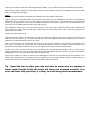
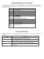
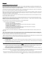
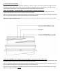
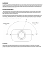
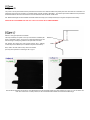
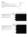
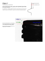
Dimensional Nomenclature
An In-Depth Guide to Programming a New Part on the AVBIS
This guide will teach you how to program preforms or single-step bottles.
Preforms (or bottles made by the following processes: single-step injection, extrusion blow, single-step stretch blow) all have a single
parting line spanning vertically from the top of the neck finish down to the base, bisecting the part into two halves. This parting-line is
formed by the two halves of the mold coming together.
When measuring a standard dimension on a bottle or preform, quality technicians typically make the initial measurement at (or just off)
the parting-line. This measurement is said to be made “AT ZERO” or “AT PARTING-LINE.” Any diameter measured at this position is
also known as “PARTING-LINE TO PARTING-LINE” or “SEAM-TO-SEAM.”
Following the initial measurement (0), quality technicians make a second measurement of the same dimension 90° from the partingline. This measurement is said to be made “at 90” or “90° to PL.”
The goal for taking measurements at the parting-line and then at 90° to the parting-line is to:
1) Detect dimensional ovality (in the case of diameters)
2) In the event of dimensional problems, the measurements provide the plant tooling department with measurements that
can be understood (tooling departments generally work in 2 axes.)
Performing these measurements by hand with calipers is relatively intuitive because you can see parting-line and position the calipers
properly based on its location.
The trick is to have the AVBIS 3000 measure the bottles/preforms in this same fashion. However, the AVBIS 3000 is unable locate the
parting-line through visual detection, as the vision system is examining the profile, not the surface, of the bottle/preform. The partingline does not “project” from the finish, and cannot be seen repeatably in profile. Therefore, a different methodology must be employed.
Threaded preforms/bottles have typically one or two thread leads, and therefore have one or two positions for the measurement of S
(for the moment, let us ignore finishes with 3 or more leads).
On a properly made set of molds, this position(s) of the S is constant to the parting-line of the preform / bottle. The AVBIS is
capable of locating this (these) S positions through use of the thread start search. Since the AVBIS can locate the S, then locating the
parting-line is simply a matter of offsetting from the position where the AVBIS measures S.
Step 1:
Press the NEW PART # button. Press the CREATE button. Save the new bottle profile as a new file with a name that will identify the
bottle. Assign your new profile to a Part Button. The assigned button will highlight green. Place the bottle (or preform in a fixture) at the
center of the rotary stage.
Step 2:
Press the DATA SETUP button. Using the red arrow buttons at the bottom of the screen, scroll to or click on the ALLOWED DATA
TYPES tab. Enable those dimensions to be measured. If multiple measurements of the same dimension are needed (e.g. width
dimensions at different heights, or HT at different shoulder locations), press the green up arrow button to enable those extra
measurements. Note that certain dimensions require that another dimension is enabled and being measured (see the requisites section
of the manual). SAVE your selections to the created bottle file.
To properly setup the Thread Start Search so you can then offset to the parting-line, ensure that you have enabled HghtL & HghtR, S,
T, and E.
Step 3:
Using the red arrow buttons at the bottom of the screen, scroll to the DATA SETUP tab. Enter Nominal and Tolerance values for each
dimension by pressing on the individual cell you wish to change and enter the new value on the pop-up keypad (values for “Left”
dimensions will automatically be copied to the “Right” of that dimension). If you need to enter a Y Position (for example, ID depth or
width heights), enter a Y Position value accordingly.
Turn the dimensions ON or OFF at the angles you do or do not wish the AVBIS to measure at.
Most preforms and single-step bottles can be setup with the following angles: 0° (the parting-line), 1 0° or 15° (10° 15° off the partingline to avoid potential flash), and 90° (90° from t he parting-line).
If you wish to add or change an angle to measure at, press the cell in the Angle column and enter in the angle on the pop-up keypad.
Note, HghtLEFT and HghtRight MUST be ON in ALL rows in which any other cell is turned ON. (Example, if F is ON at angle 65,
HghtLeft and HghtRight must be ON at angle 65).
If you wish to use the thread start search, S, T and E must be enabled at zero (0) (see the Requisites section of the manual). You will
also need to enable S at zero to setup the thread start search properly. It can be disabled later if it unnecessary to report.
Also, ensure that the zero (0) angle is setup in the first row, as this will be the first set of measurements.
Step 4:
Using the red arrow buttons at the bottom of the screen, scroll to the MEASUREMENT SETUP tab.
If the bottle finish fits within the field of view of the camera (T dimension is < 2.300”), turn ON Neck in Single Field.
Turn the Thread Start Search ON.
Set the End Offset at 15. (This will likely be changed in CAD Setup)
Set Sample Points to 1.
Set the S Type and S Offset values appropriate to the finish profile. (see the manual for descriptions of S Types and S
Offsets).
Set the Scan Speed between 10 and 40. (10 is slower, but very repeatable. 40 is faster, but isn’t as repeatable)
Set S as Datum ON.
Estimate the S Datum Offset.
o To estimate, look at the finish from overhead. Locate the S. Now mentally calculate the number of degrees from the
position of S to the parting-line you wish to label 0. If you calculated counter-clockwise from S (i.e., the parting-line
BEFORE the S), your S Datum Offset is NEGATIVE. If you calculated clockwise from S (i.e., the parting-line AFTER
the S), your S Datum Offset is POSITIVE. See drawing below for help. There is a shortcut to this that we will discuss
later….
On single step bottles and preforms, the Panel Offset value is equal to the S Datum Offset value.
-
SAVE your selections to the created bottle file. Press HIDE. The bottle/preform will be positioned at the correct height in front
of the camera (assuming you entered the correct height in HhghtL / HghtR.
Step 5:
Press the CAD SETUP button in the System Controls menu. Press HghtL. Setup HghtL to your preference.
Skip S for the moment and check T and E and ensure they are measuring in the correct places. Adjust the search limits for T and E if
required.
Press S. Press EITHER of the Find S buttons on the right side of the screen. This will begin the Thread Start Search.
1)
2)
3)
The bottle is rotated clockwise at the Scan Speed until the thread (T) projection on the LEFT side of the neck finish drops
below ½ of the T nominal value. The rotation stops.
The bottle is rotated counter-clockwise at ½ the Scan Speed, until ½ of the thread (T) is visible projecting from the sidewall (E)
on the left side of the neck finish. The rotation stops.
The bottle is rotated counter-clockwise in degrees equal to the End Offset value. End Offset is therefore is equal to the # of
degrees of neck rotation from ½ of the thread start “lead-in” to the position of S.
Press S again. Set up the limits (if required) for the S Type you have selected. Press S again if you changed any of the limits. Record
the value measured. Change the End Offset value greater OR less than 15 by clicking on the End Offset value in CAD Setup (see
illustration below.)
Press Find S again. When finished, press S again. Did the value get larger or smaller? If smaller, you are going in the correct direction
when you changed the End Offset. Continue in that direction until the S gets larger again.
When you have reached a value of End Offset that yields the smallest S, you can continue and setup other dimensions in CAD Setup.
Adjust limits and fields if necessary (see CAD SETUP section for further definitions). When you are satisfied with setup, press HIDE.
SAVE your changes when prompted.
Step 6:
Before setting up the autofeeder (if equipped), place the bottle on the rotary stage and press RUN.
Observe carefully. The Thread Start Search will run and locate the S dimension. Then, BEFORE any other values are measured, the
bottle/preform will turn the value you set in S Datum Offset in Measurement Setup (Step 4). This SHOULD have put the parting-lines
perfectly (by eye) perpendicular to the camera. The AVBIS will measure here (0° is Scan 1), then turn 10° and measure again (10° is
Scan 2), then turn an additional 80° and measure ag ain (90° is Scan 3).
If the parting-lines did NOT line up at 12 and 6 o’clock at Scan 1, then you will need to adjust the S Datum Offset in Measurement
Setup. Adjust the S Datum Offset and RUN again. Adjust until the S Datum Offset yields a Scan 1 where the parting-lines are
perpendicular to the camera.
However, there IS a shortcut to this….
Position the preform or bottle on the rotary stage such that the parting-lines are perfectly at the 12 and 6 o’clock positions (facing the
back and front of the machine, you can use the inscribed lines on the rotary stage to assist) and the S dimension (or one of the S
dimensions) is somewhere between 6 and 12. Go to CAD.
Click on S and press Find S. The Thread Start Search will run as normal. After completing, a value will appear to the left of the ”Set
Zero” button. If everything was done properly, this value (generally negative) is equal to the number of degrees between the S
dimension and the parting-line that WAS at 12. You can now use this value to properly setup the S Datum Offset.
Example, if the value is -82, that means that there are 82° between the S and the parting-line AFTER t he S. If you wish to set the
parting-line AFTER the S as 0, then the S Datum Offset (and generally Panel Offset) should be set to 82. If you wish to set the partingline BEFORE the S as 0, then the S Datum Offset should be -98 (180 - 82).
After all this is finished, the preform or bottle should be RUN again to ensure all the measurements look good and there are no
problems with the data that can be attributed to incorrect programming. If you are satisfied with the program, the bottle / preform can
then be programmed with the autofeeder and setup for data output to Excel or the network.
Tip – Spend the time to make your code such that no matter how the operator or
feeder might load the bottle, the bottle will always be measured correctly. If an
error can occur with your setup, it is likely to occur during actual measurement.
Dimensional Measurement Requisites
Certain dimensions require the measurement of another bottle feature in order to be measured. Be aware that although a
specification sheet or bottle drawing does not require a certain measurement, the AVBIS may require that measurement
for proper dimensioning.
Dim.
T
E
S
HT
X
HF
Nck
Straight
Left/Right
D
W
SU
K
HTRight,
XRight,
DRight,
etc.
Requirement
E at same angles
T at same angles
T and E at same angles
T and E at same angles
Z at same angles
F at same angles
A at same angles
Z at same angles
X Left AND Right at same angles
A at same angles
L at same angles
T and E at same angles
T and E at same angles
HghtRight at the same angle is required for ANY “right
side” measurement
Process Requirements
Certain processes will only work, or will work more efficiently, when certain other dimensions or elements are enabled or
included.
Process
Thread Start Search
Lug Search
Width
ID
Requires
T and E turned ON at the ZERO angle, Scan Speed above 0, End
Offset Set (usually between 8 and 15 degrees.
Z and B ENABLED and turned ON at the ZERO angle. Lug Offset is
always a NEGATIVE value. Scan speed should be set to 8 or below.
Y Position set at the height from the base where width should be
measured. Press AutoPanel in CAD. Adjust as necessary.
Y Position set at the depth from the sealing surface where ID should
be measured.
Concepts
1. Understanding Thread Start as a Datum Point
When measuring bottles, a datum (zero) position is needed in order to maintain repeatability. If the bottle were simply placed on the
stage and no searches (lug or thread start) were enabled, the position it was placed in would be designated “zero” by the system, and
angles of measurement would be angles from this original orientation.
This method of pre-positioning is generally not advisable, unless 1) a special bottle fixture is being used, or 2) there is no thread start
(as in the case of “snap cap” finishes and similar) and pre-positioning is unavoidable.
Relying on the operator to place the bottle in the same orientation over and over again will not be repeatable. Therefore, searches are
used to locate a known point on the bottle will ALWAYS appear IN PROFILE on the bottle. At this time, the AVBIS can use either the
“thread start” or the “lug/tab” as a point of reference.
The AVBIS was designed to measure bottles with a known thread start, and the thread start search is the most reliable and common
way to find datum point to measure from.
Thread Start search is used to find and provide a consistent rotational datum point from which other measurement positions can be
determined. These other measurement positions are defined as angles in Data Setup (i.e., “angles” defined in Data Setup are angles
FROM the thread start (unless an S Offset is entered))
Thread Start Search is set up in the Measurement Setup tab, in the Data Setup Window.
- To properly utilize the thread start search, the following are required:
- E dimension must be ENABLED
- E dimension nominal value (MUST BE CORRECT)
- E dimension MUST be turned ON at the ZERO angle (even if the data at this position is not required)
- T dimension must be ENABLED
- T dimension nominal value (MUST BE CORRECT)
- T dimension MUST be turned ON at the ZERO angle (even if the data at this position is not required)
- End Offset Value in Measurement Setup (explanation below)
- Scan Speed Value (typically between 10 and 30)
- Thread Start Search can be tested in CAD Setup, if S is ENABLED and turned ON at ZERO. Otherwise, it will only function in the
RUN mode.
- Bear in mind that bottles formed by 2-stage production (injected preform to blown bottle) typically do NOT have a consistent datum
point in relation to their body panels (i.e., the rotational position of S is not always in the same position in relation to the parting line of
the body of the bottle). Their datum IS consistent with other neck finish locations.
- NOTE: The actual S dimension, usually (BUT NOT ALWAYS!) found at the thread start, is NOT RELEVANT to the thread start search.
However, measuring the S is often useful for determining the End Offset (explanation to follow).
How Thread Start Search Works
4)
5)
The bottle is rotated clockwise at the Scan Speed until the thread (T) begins to disappear on the LEFT side of the neck finish.
The rotation stops.
The bottle is rotated counter-clockwise at ½ the Scan Speed, until ½ of the thread (T) is visible projecting from the sidewall (E)
on the left side of the neck finish. The rotation stops.
The rotational position of ½ of T on the neck fini sh is an extremely repeatable location to find, even if the bottle is improperly
blown.
6)
7)
The bottle is rotated counter-clockwise in degrees equal to the End Offset value. End Offset is therefore is equal to the # of
degrees of neck rotation from ½ of the thread start “lead-in” to the full thread and/or position of S.
After rotating the End Offset, the rotational position is SET as zero (unless a Thread Datum Offset is entered, see below). All
measurement angles will be referenced from this position.
END OFFSET IS GENERALLY NOT NOTED ON BOTTLE DRAWINGS. THEREFORE, EXPERIMENTATION OR APPROXIMATION
WILL BE NEEDED TO FIND THE PROPER END OFFSET FOR EACH BOTTLE.
Assume that all bottles are different, despite similar neck finishes. Therefore, there is no “golden” standard or template that all bottles
will adhere to. Just as the molds and processes that produce each bottle are unique, each bottle program should be unique to the
bottle.
2. How Do I Determine End Offset?
There are TWO ways to determine the End Offset, depending on whether you want to set the actual Thread Start (zenith of thread) or
the position of S as the datum (zero) position. Since the End Offset is typically NOT noted on bottle drawings, and is not consistent
between different bottles finishes, it must be determined through experimentation and/or trial and error.
USING THE POSITION OF S AS DATUM (ZERO) – Recommended for most bottle manufacturers
First, make an approximation of the angle from ½ of the thread start to the point where S is measured (usually between 8 and 22
degrees). Enter this approximation into the End Offset in Measurement Setup.
Next, go to CAD Setup. Measure the S dimension and press the Find S button. When the thread start search is complete, remeasure S.
Now, change the End Offset value in CAD. Repeat the Find S procedure. Remeasure S.
Repeat this process of adjusting the End Offset, performing the thread start search and measuring S until End Offset yields an angle
where the S measurement is at its lowest.
USING THE POSITION OF FULL THREAD (T) AS DATUM (ZERO) – Recommended only for 28mm CSD
First, make an approximation of the angle from ½ of the thread start to the point where T has reached its zenith (usually between 8 and
22 degrees). Enter this approximation into the End Offset in Measurement Setup.
Next, go to CAD Setup. Measure the S dimension and press the Find S button. When the thread start search is complete, measure T.
Now, change the End Offset value in CAD. Repeat the Find S procedure. Remeasure T.
Repeat this process of adjusting the End Offset, performing the thread start search and measuring T until End Offset yields an angle
where the T measurement reaches nominal.
3. S Datum Offset
If S as Datum is turned ON, the Thread Start Search will run as normal. However, after turning the End Offset value (and measuring S if
enabled), the bottle will then turn from this position a value equal to the Thread Datum value. Both negative and positive values can be
used (Positive values will turn the bottle counter-clockwise, negative values will turn the bottle clockwise). This offset position from the
thread start will be set as ZERO for all NECK FINISH measurements. The offset position will NOT be set as zero for Panel (Width)
measurements (unless entered in Panel Offset).
4. Why Use Thread Datum Offset?
“0” is at the parting-line, NOT at S.
- Most manufacturers call out the parting-line to parting-line (seam-to-seam) measurement “0” and then measure “90° to the parting
line.” While the data can be moved around by Excel or with most competent SPC software programs, it may be easier to have the
AVBIS “speak” the same way the manufacturer does.
- For example, let us assume we have a bottle with the thread start and S dimension at exactly 90° fro m the parting-line. The customer
still wants to search for the thread start (and also the S dimension), but then wants to call the parting-line to parting-line position as “0°.”
In this scenario, a thread datum offset of 90° (or -90° depending on direction desired) can be entered . Bear in mind, if the bottle has
flash at the parting-line, 90° may not be ideal. Ad just as necessary, or add a third angle (example, 0° (Parting-line), 10° (ten degrees
from parting-line), and 90° (ninety degrees from pa rting-line)).
5. Panel Offset
Panel Offset applies to the body panel offset from the thread start rotational position. Panel Offset is useful for determining a specific
rotational position for the first width measurement (the zero angle for width). Panel Offset is one of two ways to set up specific
orientation of the bottle for measuring bottle body widths. Most single stage bottles (bottles NOT produced from a randomly injected
preform) have a panel offset that matches the thread datum offset.
S Types
S Type = 0
Two points on the top of the thread and two points above the thread on the E wall are measured to provide points from which lines are constructed. The
intersection of the lines is the S position. The S offset number (in pixels) provides a ‘dead band ‘. The intersect point will be shifted to the first point within
the dead band where the lines could intersect to avoid an intersection within the thread -E wall radius.
Use: Bottles with straight and clean sidewall and thread surfaces and sharp (non-rounded) intersects (such as glass and specific PET finishes)
AVID DOES NOT RECOMMEND THE USE OF S TYPE 0 FOR PLASTIC BOTTLE MEASUREMENT.
S Type = 1
(S Offset = 4 - 10)
Easiest to setup if prerequisites are satisfied.
The slope created by two points on the top of the thread is calculated (the
slope is calculated in pixels). The top is then examined towards the E wall
until the change in the slope is greater then the pixel value of S-offset.
Use: Bottles with straight and clean thread surfaces with a relatively
constant slope to the sidewall. (such as HDPE and specific PET finishes)
Note, “striker” cuts that create a “step” close to the intersect
point may cause problems in measuring S with S Type 1.
Note the above CAD Setup screens above. The sidewall above the intersect slants slightly and is short; therefore S Types 0, 2, 3 are not ideal for the
finish. Also note the lack of a sharp intersect; S will be measured inside a radius and measurements MAY range.
S Type = 2
(S Offset = varies)
Best used on 28mm CSD finishes.
Measures the S by locating the E wall above the thread, and then calculating the first point on
the thread that is S offset out from the E wall.
Use: Bottles with “flat-top” threads (little or no slope, such as a 28mm PCO finish), artifacts on
sidewall, “striker steps” (such as “rough cut” HDPE and other problematic finishes)
(Note: S Type 2 requires that the operator set an “upper search limit” (USL) for the S
measurement in CAD setup. The USL will be the position along the sidewall that S offset
“steps away from.”)
On the finish to the right, the USL has been set to
intersect the sidewall above the thread. An offset of 8
has been entered, therefore the AVBIS will step out 8
pixels from the intersect of the USL and the sidewall and
measure down to the thread.
Note that the thread profile is flat at the intersect.
Therefore, S Types 0, 1, 3 and 4 would not work since
they rely on the slope of the thread for calculation.
On the finish to the right, the USL has been set to intersect the
sidewall above the “cutter step” above the thread. An offset of
11 has been entered; therefore, the AVBIS will step out 11
pixels from the intersect of the USL and the sidewall and
measure down to the thread.
If the measurement down to the cutter step were desirable, and
smaller S offset could be entered, reducing the number of
pixels to step out.
Theoretically, S Type 1 could also be used for this finish.
S Type = 3
(S Offset = 1)
Most repeatable S method if prerequisites are satisfied.
S Type 3 is essentially the same as S Type 0 except that all points between an upper and
lower search limit (set by operator) are used to calculate a line intersect.
All points on the top of the thread between 25% and 75% of nominal thread projection
and all points on the E wall between search limits are measured to provide points from
which best fit lines are constructed. The intersection of the lines is the S position. The S
offset number (in pixels) provides an accept band. The intersect point will be shifted to the
first point within the accept band where the lines could intersect to avoid an intersection
within the thread -E wall radius.
Use: Bottles with straight and clean sidewall and thread surfaces (mainly PET products or
clean injection molded finishes).
Note, in both of the CAD Setup
screens to the right, the sidewall
above the thread is very straight
And long, allowing many points to
Be gathered between the USL and
LSL.
Also note the constant slope of the
thread profiles.
S Type = 4
(S Offset = 3 - 7)
Only methodology for rounded threads.
S Type 4 is the reverse of S Type 1. S Type 4 scans the sidewall below the operator
placed search limit for a change slope greater than the S Offset value. Typically, an offset
of 4 is used on most bottles.
Use: Bottles with a straight sidewall that remains mostly straight until the thread slope
intersect. S Type 4 is also the ONLY S Type that can be used on rounded thread profiles.
Note the rounded thread (non-constant slope)
of the thread profile to the right. S Types 0,1,
2, and 3 would not work on this bottle finish.
Also note that the USL has been set on a
straight “spot” on the sidewall.
Setting Up Widths
Measurement
- Width of bottle from body panel to opposite body panel
Data Setup Entry
- Nominal Value set to zero (because there is no “depth” measurement, and measurements are never flagged as out of spec by the
AVBIS, the width nominal can be set as zero)
- Tolerance Value set to zero (see above)
- Y Position (height from bottle base to location where width measurement should take place)
CAD Setup Entry
- Press the Width 1 button. After it completes the search, press the AutoPanel button.
The system will automatically go to each of the selected Y positions for each width measurements and determine the width search
areas. The AVBIS will measure the MAX width within a .2 inch search area above and below the specified Y position. This search area
can be changed by clicking the desired width button and moving the upper and lower search limits. The search can be changed to a
MIN search by clicking the desired width button and pressing the MIN button.
VASTLY DIFFERENT WIDTH HEIGHTS (FOR EXAMPLE, ONE WIDTH AT 0.5” @ 0 DEGREES AND THE OTHER AT 4.0” @ 90
DEGREES ) REQUIRE 2 WIDTH DIMENSIONS TO BE ENABLED.
Width 1 and the MIN/MAX Width Search
Min and Max Width Searches use the height set in “Width Search Height” in Measurement Setup as a search point to
determine bottle orientation. Be sure that when using Min or Max Width Searches that the height will provide a useful
reference point for the search.
DATA HANDLING W/ EXCEL
1) Create or load a spreadsheet file for use as a template with the bottle profile you desire. Load it onto the AVBIS or onto
the local network into a location of your choice that will not be changed.
2) Select bottle profile you wish to enable for data output by selecting the appropriate part button. Press the Basic Setup
button in the System Controls menu. Select the System Tab. Press the Worksheet File button. Select the spreadsheet
file you loaded or wish to use.
3) If the spreadsheet is organized by rows (most common) select the By Rows option in the setup.
If it is organized by column, select the By Column option. Determine the starting row or column number for data entry,
and put that number in First On Sheet. (Note: make sure that in Excel the columns and rows are labeled by number and
not by letters. If there are letters, go to Tools, Options, click the General tab and check the R1C1 Reference Style box.
Save the Excel file with this change.)
4) On the System Tab, press SAVE. Save it to the bottle profile. Now, everytime the bottle part button is selected it will
automatically open the Excel spreadsheet as well. Be sure to go into Excel and Save As a different filename following
bottle measurements, otherwise the AVBIS will overwrite your template with data!
5) With the desired bottle button highlighted, Press the Data Setup button in the System Controls menu. Using the red
arrow buttons scroll over to Excel Setup. Select the appropriate cells for the data and angle combination that corresponds
with the correct cell number on the spreadsheet. Once entered press SAVE. All data collected during measurement will go
into the appropriate cells on the spreadsheet when the Send Data button is pressed in System Controls. Data is sent
automatically when using the Feeder option. Save the Excel worksheet in Excel following measurement using Save As.
DO NOT OVERWRITE THE TEMPLATE FILE WITH DATA OR IT WILL BE LOST THE NEXT TIME IT IS RUN!
Tip – The AVBIS may require certain dimensions to be enabled or certain angles
to be turned on. However, the data from these measurements may not be
required for collection. Simply ignore these data cells when setting up for Excel.
While the AVBIS will continue to measure these dimensions/angles, the data will
not be exported.
DATA HANDLING W/ DATA FILE
1) Select bottle profile you wish to enable for data output by selecting the appropriate part button. Press the Basic Setup
button in the System Controls menu. Select the System Tab. Press the Data File button. Locate a destination folder and
name the data file you wish to create when the AVBIS completes measuring a bottle. .dat, .txt, and .csv are generally
acceptable suffixes.
2) Confirm the delimiter (comma is generally accepted by most SPC programs).
Now whenever the bottle is finished measuring, the data will go to the set remote data file.