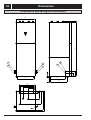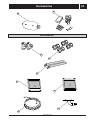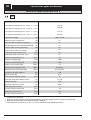
1
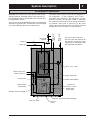
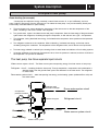
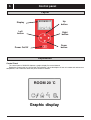
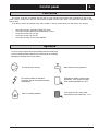
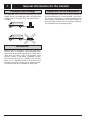
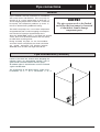
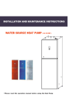
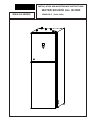
INSTALLATION AND MAINTENANCE INSTRUCTIONS
WATER SOURCE ALL IN ONE
WWA-SS SERIES
WWA-SS-8 ( 230V / 50Hz )
1
Contents
System description
Control
Principle of operation ............................................ 3
Unit Description .................................................... 3
Principle of heatpump ........................................... 4
Control panel
Layout ..................................................................
Explanation ..........................................................
Functions .............................................................
Symbols ...............................................................
5
5
6
6
General information for the installer
Transport and storage ............................................ 7
Installation .............................................................. 7
Inspection of the installation .................................. 7
Pipe connections
General .................................................................. 8
Pipe connection (collector) .................................... 8
Pipe connection (Room water side) ...................... 9
Pipe connections (water heater) ............................ 9
Pump capacity diagrams, Room water side ........ 10
How to adjust the rate of flow .............................. 10
Pump capacity diagrams, collector side .............. 11
Electrical connections
Connect the power cord ....................................... 12
Wiring of the terminal (mode one) ......................... 13
Wiring of the terminal (mode two) ......................... 13
Connecting the room temperature sensor ........... 14
Connecting the outside temperature sensor ........ 14
Layout of the PCB ............................................. 15
1.5mm2 terminal connection ............................. 15
Part of wiring diagram ........................................ 16
2.5mm2 / 6mm2terminal connection ................... 16
Wiring diagram ( 230v / 50 Hz ) ............................ 17
Description of the switch board .............................18
Commissioning and adjusting
Preparations ........................................................ 19
Filling the room water cycle system .................... 19
Inspection ............................................................. 20
Adjust the Water source / Room water cycle pump ...... 20
Readjusting, Room water side .............................. 20
Emptying the water heater ................................... 20
General Information .............................................. 21
Menus ................................................................... 22
Main Menu Information ......................................... 22
Sub-menu Operation.............................................. 22
Sub-menu Heat Curve ........................................... 23
Sub-menu Temperature ........................................ 24
Sub-menu Integral ................................................. 24
Sub-menu Operating Time .................................... 25
Sub-menu Reset ................................................... 26
Sub-menu Man Test .............................................. 26
Adjustments to be made regularly ........................ 26
Heat Generation-General....................................... 26
Adjustment of the CURVE valve ........................... 27
Adjustment of ROOM valve.................................... 28
Adjustment of Part of the Heat Curve .................... 29
Adjustment the MIN and MAX valve ..................... 30
Adjustment of the HEAT STOP valve......................31
Graph of recent change in TEMPERATURE............
32
Maximum Return Line Temperature ..................... 33
Warm or cool water Production............................... 33
Regular checks .......................................................34
Check of the Operating Mode ............................... 34
Checking the Water Level of the Room system .... 35
Checking the safety valves .................................... 35
In the event of leakage .......................................... 35
Alarm Messages .................................................... 36
Terminology and Abbreviations ............................. 37
Dealing with malfunctions
Draining, Room water cycle side ........................ 38
Draining, water tank.............................................. 38
Draining, collector side ........................................38
Draining, the chassis............................................. 38
Component placement
Component positions 1 ........................................ 39
Component positions 2......................................... 40
Component positions 230 V / 50 HZ .................... 41
List of components
List of components ................................................ 42
Dimensions
Dimensions and setting-out coordinates .............. 43
Accessories
Accessories .......................................................... 44
Enclosed kit .......................................................... 44
Technical specifications
Technical specifications 230 V ............................ 45
System description
2
Principle of operation
Expansion
vessel
Water in
Water out
Room-water
flow
The heat source of the WWA-SS series is provided from
seawater or ground-water. The titanium heat exchanger
is used for collecting the heat of water-source.
The Water-source emits its heat to the refrigerant in
the evaporator. It then vaporises and is compressed in the compressor. The refrigerant, the temperature of which has now been raised, is passed to
the condenser where it gives off its energy to the heating medium circuit and, if necessary, to the water
heater. After the condenser there is a built-in electrical
module which cuts in if there is a high demand.
Room-water
return
WWA-SS series consists of a heat pump, water heater,
electrical module, circulation pumps and a control system. WWA-SS series is connected to the collector and
heating medium circuits.
The room water side and
the hot water side must be fitted with the necessary safety
equipment in accordance with
the applicable regulations.
Three - way valve
Water-source out
Water-source in
Room-water flow
Compressor
Room-water Return
Water-source
Cycle pump
Electrical
auxiliary heater
Room-water
Cycle pump
Titanium heat exchanger
Stainless steel plate heat exchanger
Four-way valve
Expansion
valve
3
System description
Unit Description
In order to get the best results from the climate system WWA-SS series you should read through the
section For the System manager in these Installation and Maintenance instructions.
WWA-SS series is a climate system for heating houses and apartment buildings as well as industrial
properties. Ground-water and seawater can be used as the heat exchange source.
WWA-SS series is a complete heating installation for heating and hot water.
It is fitted with new design on the market to be developed specifically for heat pumps. A new evaporator enables
a new and improved circulation system for the refrigerant. The heat pump has an integrated 150 or 200 litre water
tank and an immersion heater. The Tap Water Stratification system improves the efficiency of heat transfer by keeping
the water in distinct thermal layers in the water tank.
The unit is fitted with a regulating computer , which is controlled over a graphic display unit.
Heat is distributed throughout the house over a hydronic heating system referred to as low temperature
system with a maximal water temperature to radiators (supply line temperature) of 65°C. Most of the heating
demand is taken care of by the heat pump (compressor unit), the auxiliary heater being started only when
demands exceed available heat pump capacity.
WWA-SS series consists of five main components:
a. Heat Pump Unit
Rotory or Scroll-compressor
Stainless steel heat exchangers
Circulation pumps for Ground-water sytem and heating systems
Valves and safety equipment for refrigerant system, complete with necessary electric components
b. Water Heater /cooler
150 or 200 litre
Lined with copper sheet against corrosion or made of stainless steel
Maintenance free as no anode is used
c. Reversing Valve
Opening or closing the connection to water heater according to operating mode: heating or warm water
production
d. Auxiliary Heater
3/6/9 kW electric heating element
Three-step capacity control
Fitted on supply line
Delivers back-up heat in case of great heat demand that exceeds heat pump capacity
Starts automatically, provided operating mode “AUTO” has been selected
e. Regulating Equipment
The regulating system controls heat pump components (compressor, circulation pumps, auxiliary heater and
reversing valve). Based on data received from sensors, it starts or stops heat pump operation and determines
whether heating or warm water shall be produced. The system consists of:
Control computer with graphic display unit
Temperature sensors (outside air,room, supply line, return line,and Ground-water system)
System description
4
Principle of heat pump
Room heating (for example)
A heat pump can exploit the energy contained in natural heat sources. Or, to put it differently, the heat
pump ”collects” heat energy from the heat source. This makes the heat pump a very environmentally friendly and
economically sound alternative for space heating.
a.
The ground water cycle sytem absorbs the heat energy of the heat source so that the temperature of the
water circulating in the hose is raised a few degrees.
b
The ground-water sytem is circulated to the heat pump’s evaporator. Here the heat energy of the ground-water
sytem causes the refrigerant, circulating through the evaporator, to boil and turn into a gas – it evaporates.
c
The refrigerant, having absorbed heat energy, is circulated to the compressor where pressure and temperature
are raised.
d
The refrigerant continues to the condenser. When condensing, it releases heat energy to the heat carrier,
circulating through the condenser. The temperature of the refrigerant sinks, and it returns to its liquid state.
e
The heat energy released is carried by the heating circuit to water heater and radiator or floor heating systems.
f
At last the refrigerant is led through the expansion valve, where its pressure is reduced, and then continues to
the evaporator The process is restarted.
.
The heat pump has three separate liquid circuits
Water-source sytem circuit – The Water-source system transporting energy from heat source to heat pump.
Refrigerant circuit – circulating inside the heat pump. Through evaporation, compression and condensation it
absorbs energy from the ground-water sytem and releases it to the heat carrier. The refrigerant
is chlorine-free.
Room-water system circuit – water transporting heat energy to the heating system (radiators/floor coils) and
the water heater.
Stainless steel
plate heat exchanger
Room-water system circuit
Compressor/
pressure increase
pressure drop part
Refrigerant circuit
Refrigerant
Titanium heat exchanger
Room heating
Water-source system circuit
Room cooling
Water-source system
5
Control panel
Layout
o
ROOM 20 C
Display
Up
button
Left
button C
DRight
button
Down
F button
Power On/Off A
Explanation
Control Panel
The control panel of WWA-SS features a graphic display five control buttons
.
Beside the control panel you will find the User’s Manual, a short description of how to increase and reduce room
temperature, and a label with name and phone number of dealer.
o
ROOM 20 C
Graphic display
Control panel
6
Functions
The control computer is operated with the help of a user friendly menu system that is displayed on the contr ol
panel. There is a main menu and four sub-menus accessible from the main menu. The menus are described in detail
further down.
To be able to select the desired menu and increase or reduce preset values, you will use the five buttons.
•
•
•
•
•
One butto n poin ting
One button pointing
One button pointing
One button pointing
One button pointing
upwar ds marked with a plus
downwards marked with a minus
to the right
to the left
to the Power ON/OFF
Symbols
For you to know at a glance the actual operating mode of the heat pump,
one of the following symbols will be shown in the lower part of the display
depending on which part of the unit is working:
The heat pump is running.
Warm water is being produced.
The auxiliary heater is activated.
The figure next to the symbol indicates
capacity step.
Indicates the status of warm water
production. If the symbol is empty,
warm water temperature is 44°C.
There is a heating demand.
If the symbol is full, warm water
temperature is the start temp. + 4°C.
7
General information for the installer
Transport and storage
Inspection of the installation
The WWA-SS series must be transported and stored
upright and dry. The WWA-SS series may however be
carefully laid on its back when being moved into
a building.
Current regulations require the heating installation to
be inspected before it is commissioned. The inspection must be carried out by a suitably qualified person
and should be documented. The above applies to
closed heating systems. If the heat pump is replaced,
the installation must be inspected again.
H M flo w
4 9 (5 0°C
)
H o t w a te r 5 1°C
-2
0
+2
1
0
R
0
+2
0
-2
H M flo w4 9 (5 0°C
)
H o t w a te r 5 1°C
1
R
Installation
WWA-SS series is placed on a firm base, preferably a
concrete floor or foundation. Install WWA-SS series
with its back to an outside wall, ideally in a room where
noise does not matter. If this is not possible, avoid
placing it against a wall behind a bedroom or other
room where noise may be a problem. Any wall that
backs on to a bedroom should be fitted with sound
insulation. Route pipes so they are not fixed to an internal wall that backs on to a bedroom or living room.
Pipe connections
8
General
Pipe installation must be carried out in accordance
with current norms and directives. The heat pump can
operate up to a return temperature of about 58* °C
and an outgoing temperature of about 70* °C from the
heat pump. The compressor produces up to 65* °C,
the rest is obtained using additional heating.
The other heat pumps has a max return temperature
of approximately 50 °C and an outgoing max temperature from the heat pump of approximately 60 °C.
Since the WWA,WWB series is not fitted with shut-off
valves, these must be fitted outside of the heat pump
to make future servicing easier.
During assembly the pipes for the heat medium
and water heater and possibly hot water circulation
are routed backwards. The distance between
WWA-SS series and the wall ought to be 50 mm.
NOTE!
The pipe system needs to be flushed
out before the heat pump is connected
so that debris cannot damage
component parts.
Pipe connections (collector)
Factors to be taken into account when designing the
collector layout are geographical position, type of
ground water and cover factor of the heat pump.
All collector pipes in heated rooms must be insulated
against condensation.
The temperature of the Water-source system must
be between -12 °C ---- 10 °C .The default is -12 °C
9
Pipe connections
Pipe connections (Room
water side)
Pipe connections for the heat medium side are made
at the top. All required safety devices, shut-off valves
(as close to the heat pump as possible), and particle
filter (supplied) are fitted.
When connecting to a system with thermostats on all
radiators, a relief valve must be fitted, or some of the
thermostats must be removed to ensure sufficient
flow.
Pipe connections (water heater)
The heat pump´s water heater must be fitted with the
necessary valve equipment.
VENTING VALVE
P
EXP
SAV
Ground-water
HW CW
SAV
SF
Water-source in
Water-source out
SF
Water-source
Water-source in
SF
Particle filter
Water-source out
SF
Particle filter
The heat pump should be supplemented with an electric water heater if a bubble pool or other significant
consumer of hot water is installed. The valve coupling
in COMPACT (electrical water heater) can be divided.
The mixing valve stays in COMPACT and the remaining valve coupling can be used for incoming cold
water in WWA-SS series.
NOTE!
The venting valve should be set on
the top of the heating medium system.
10
Pipe connections
Pump capacity diagrams, Room-water side
WWA-SS-8
Available
pressure
kPa
80
70
60
50
40
30
20
10
0
1
2
3
Flow
0
0.22
0.44
0.66
0.88
1.10
1.32
1.54
WILO RL-25/8
How to adjust the rate of flow
WILO RS-25/8
The
pump
is
adjustable to adjust
the flow: 1, 2, or 3.
1.76
l/s
11
Pipe connections
Pump capacity diagrams, collector side
WWA-SS-8
Available
pressure
kPa
80
70
60
50
40
30
20
10
0
1
2
3
Flow
0
0.22
0.44
0.66
0.88
1.10
1.32
1.54
WILO RS-25/8
How to adjust the rate of flow
WILO RS-25/8
The
pump
is
adjustable to adjust
the flow: 1, 2, or 3.
1.76
l/s
Electrical connection
Connect the power cord
N
L
G
( 230V / 50 HZ )
NOTE!
Electrical installation and service must
be carried out under the supervision of
a qualified electrician in accordance
with the stipulations in force.
12
13
Electrical connection
Wiring of the terminal (mode one)
Step1
Step2
Step3
Wiring of the terminal (mode two)
Step1
Step2
Step3
Electrical connection
14
Connecting The Room Temperature Sensor
RT
OCT
Room temperature sensor
Room temperature sensor
RT=Room temperature sensor
Connecting The Outside Temperature Sensor
RT
OCT
Outside air temperature sensor
Outside air temperature sensor
OCT=Outside air temperature sensor
HP
LP
CSP
WCP2
GND
N
GND
N
From
From Neutral line
common terminal
From Fuse 3
WSCP2
GND
CON3
N
OUT1
From Water cycle pump2
From Fuse 2
From Neutral line
common terminal
From
WCP
COM
OUT2
From Water source cycle pump2
From Fuse 3
From Neutral line
common terminal
From
GND
COM
From Water cycle pump
From
WSCP
CN1
N
From Neutral line
common terminal
From Fuse 2
From Neutral line
common terminal
NO
From Water source cycle pump
From PCB / OUT8
4WV
1
N
From
GND
Water Outlet Temp
2
From Four-way valve forwaterflow
EHI
3
From Neutral line
common terminal
4
N
5
From Three-way valve forwaterflow
Water Inlet Temp
6
From Fuse 1
7
OUT5
3WV
8
Water Source Outlet Temp
9
From PCB / CON5 /7,8
OUT6
From Electrical auxiliary heater
Temperature Sensor
Outdoor Condition Temp
13 12 11 10
From
Room Temp
16 15 14
OUT7
GND
From PCB / CON5 /5,6
High Pressure
Water tank Temp
Low Pressure
Water Source Inlet Temp
Compressor Gas Outlet Temp
Compressor stoped protection
OUT8
From Adjustable pressure switch
From PCB / CON5 /3,4
COMP
From Low Pressure Pressostat
From Water Tank Temperature Sensor
From PCB / CON5 /1,2
From Room Temperature Sensor
WSIT
From High Pressure Pressostat
From Outside Air Temperature Sensor
From PCB / CON4 /15,16
From Water source Outlet Temperature Sensor
WTT
From Compressor Gas Outlet
Temperature Sensor
From PCB / CON4 /9,10
RT
From PCB / CON4 /13,14
From PCB / CON4 /7,8
OCT
From Groundwater Inlet
Temperature Sensor
From PCB / CON4 /5,6
WSOT
From PCB / CON4 /11,12
From PCB / CON4 /3,4
WIT
From Water Inlet Temperature Sensor
Electric Heater interruptor
CON5
From PCB / CON4 /1,2
3 Phase Or Single Phase
12 11 10 9 8 7 6 5 4 3 2 1
WOT
From Water Outlet Temperature Sensor
15
Electrical connection
Layout of the PCB
NO
OUT4
CN2
PCB
CON4
TRANSFORMER
R N
L C D
1.5mm2 terminal connection
Electrical connection
16
Part of wiring diagram
Water Cycle
Pump
3A
F3
BLUE
16A
F4
Heater 1
16A
F5
Heater 2
BLUE
BLUE
A2
C1
Y/G
BLUE
COMPRESSOR
CONTACTOR
A1
Neutral line
common
terminal
2A
F1
N
3 way valve
WCP2
4 way valve
Y/G
BLUE
Water source
Cycle Pump
N
3A
F2
WSCP2
C2
cm
R
C
RED
Y/G
WHITE
WHITE
T1
L1
BLACK
L N
S
C1
K1
2.5mm2 / 6mm2 terminal connection
From Electrical heater 1
EH1
From Fuse 4
From Electrical heater 2
EH2
From Fuse 5
From Compressor
GND
From
From Electrical heater / N
N
From N
From Compressor / S
S
From C2 / S
From Compressor / R
R
From C2 / R
From Compressor / C
C
From C1 / L1
Low Pressure
High Pressure
OUT6
OUT5
CON4
PCB
Water tank Temp
Compressor stoped protection
OUT8 OUT7
Room Temp
OUT9
Outdoor Condition Temp
Electric Heater interruptor
OUT4
Water source Inlet Temp
Compressor Gas Ooulet Temp
WHITE
BLACK
C
RED
R
L C D
R
TRANSFORMER
CON3
S
CN2
C2
N
COM
OUT1
COM
NO
BROWN
OUT2
NO
CN1
BLACK
BLACK
Water Outlet Temp
cm
Water Inlet Temp
3 Phase Or Single Phase
Water source Outlet Temp
BLACK
AO
BLACK
BLACK
L1
AA
3A
F2
2A
F1
T1
BLACK
Switch board
BLACK
WHITE
BA
A1
Water source
cycle pump
4 way valve
3 way valve
COMPRESSOR
CONTACTOR
A2
BLUE
16A
F5
Heater 2
BLUE
Heater 1
16A
F4
BLACK
BLACK
Y/G
BLACK
Neutral line
common
terminal
BLUE
Water cycle pump
WCP2
WSCP2
Y/G
Y/G
3A
F3
BLUE
BLUE
N
N
BLACK
N
L
CON5
220V 50HZ
17
Electrical connection
Wiring Diagram( 230V / 50 HZ )
BLACK
Description of the switch board
18
A0 1 : Control the compressor;
AA M : Control the Water source cycle pump;
BA M
Connect to Fuse 3
AA M
Switch board
When test or repair the machine, the compressor,
Water source cycle pump and water cycle pump
can be force manual startup.
Connect to Fuse 2
Function of manual switch board:
A0 1
Connect to
compressor contactor (A1)
Function
BA M : Control the water cycle pump.
Connect to the Air break switch ( L ) ( 230V/ 50 HZ )
Initial state
The initial state of the manual switch board are such buttons ( A0 , AA , BA ),
all of them are off.(see the picture).
BA M
AA M
A0 1
Switch board
When the machine is running normally,the switch board must be in initial state.
NOTE!
The manual switch board is use only if the
necessary for test or repair. when the
machine is running normally,the switch
board must be in initial state.
19
Commissioning and adjusting
Preparations
Before starting up the system, check that the heating,
collector and hot water circuits are full and thoroughly
vented. Check the pipe system for leakage.
Filling the
room water cycle system
The heating medium system is filled with water until
the required pressure is reached and then vented.
1. Check the heating medium system for leakage.
2. Connect the filling pump and return line on the
heating system's service connections as shown in
figure.
3. Close the valve under the level vessel.
4. Close the valve between the service connections.
5. Open the valves on the service connections.
6. Close the valve of the water tank and heating medium.
7. Start the filling pump, and fill until there is fluid in
the return pipe.
8. Maintains the travelling schedule pole of the Threeway valve for waterflow at the middle position.
9. Press the power ON botton on the control panel.
and start the heating medium pump.
10. The filling pump and the room water cycle pump
are now operational. The fluid should circulate via
the container with tap water until it emerges from
the return hose without being mixed with air.
11. Stop the filling pump and clean the particle filter.
12. Start the filling pump, open the valve between the
service connections.
13. Close the valve on the service connection's return
line. Now pressurise the system (to max 3 bar)
with the filling pump.
14. Close the valve on the service connection closest
to the level vessel.
15. Stop the filling pump.
16. Fill the level vessel with liquid up to around 2/3.
17. Open the valve below the level vessel.
18. Close the Room water cycle pump.
19. Select the auto operating mode using the
operating mode button.
AV
Closes
AV
AVT
AV
SF
SÄV
water in
water out
AVT
SÄV
Draining
Safety valve
NK
SF
NK
Particle filter
Level vessel
Commissioning and adjusting
20
Inspection
Adjust the Water source/
Room water cycle pump
1). Read the water source temperatures on the panel.
The defference between these two temperatures
should be 2—5°C when the system has come into
balance. Adjust the flow with the knob on the water
source cycle pump (32). A high difference indicates a
low ground water flow. A low difference indicates
a high water source flow.
The
pump
is
adjustable to adjust
water source flow.
2). Check the flow temperature and the return
return temperature on the panel. The difference
between these two temperatures, with floating
condensing, should be 5 — 10 °C when the house
is being heated without additional heat. Adjust the
flow with the knob on the room-water cycled pump
(34). A high difference could depend on a low roomwater flow. A low difference indicates a high
room-water flow.
NOTE!
The compressor must not be forced to
start with periods shorter that 1 start
per 15 minutes.
Readjusting, Room water side
Air is initially released from the hot water and venting
may be necessary. If bubbling sounds can be heard
from the heat pump, the entire system requires further
venting. When the system has stabilised (correct
pressure and all the air removed) the heating controls
can be set at the required values.
2/3
Emptying the water heater
The
pump
is
adjustable to adjust
Room-water flow.
The siphon principle is used to empty the water
heater. This can be done either via the drain valve on
the incoming cold water pipe or by inserting a hose
into the cold water connection.
21
Control
General information
Menu Navigation
The right-hand button on the con trol panel is used to open the desired menu. The left-ha nd button is used to
return to the pr evious men u. The up and down butt ons are used to navigate betw een the parameters of a menu.
A cu rs or (arrow) on the left-hand side of the display indica tes which me nu can be op en ed . The up and down buttons
are also used if you wish to increase or reduce a preset value.
Display of current operating mode
During normal operation, the following in formation will be displayed:
• Desired (preset) room temperature
• Whether there is a heating demand or not. If there is, there will also be symbols
telling which heat source is working– heat pump or auxiliary heater or both (see ”Symbols” on page 6) .
• Which operating mode has been selected In addition to this, the following messages may be displayed:
• PHASE SEQUENCE
The compressor in the heat pump is running in the wrong direction, which means that heat is produced by the
auxiliary heater only (see ”Alarm” on page 36).
• HIGH RETURN (for room heating)
The temperature of the water returning from the radiators is too high so the heat pump will not be allowed to
produce heat. (see ”Alarm” on p. 36).
• LOW RETURN (for room cooling)
The temperature of the water returning from the radiators is lower than 5 °C , so the heat pump will be stopped.
(see ”Alarm” on p. 36).
• START
The heat pump is in the processs of starting. There is a 30 second delay bet- ween start of Ground water sytem
pump and compressor.
• START_MIN
The heat pump will start in the number of minutes indicated in the display.
Control
22
Menus
Main Menu INFORMATION
To open the main menu INFORMATION, press the right- or left-hand button once.
Return
Open next
menu
INFORMATION
OPERATION
HEATCURVE
TEMPERATURE
INTEGRAL
OPER TIME
RESET
MAN TEST
Sub
menus
.
To select the desired sub-menu use the up or down button.
Open the menu by pressing the right-hand button once.
To return to the main menu, press the left-hand button once.
Sub-Menu OPERATION
OPERATION
ROOM AIR
COO L / HEAT
WARM
/ COO L WATER
HEATPUMP
ADD HEAT
.
ON
OFF
This menu is used for the selection of operating mode. The control system allows for five different operating
modes:
•
OPERATION HEAT PUMP ON
Heat pump (compressor) operation is allowed by the control system.
•
OPERATION HEAT PUMP OFF
Heat pump (compressor) operation is not allowed by the control system.
•
OPERATION ADD.HEAT ON/OFF
The auxiliary heater will/will not be allowed to operate. This operating mode is normally used when a new
installation is being put into service, before the Water system is ready for use.
• OPERATION ROOMCOOL (Choose ROOMAIR First)
The heat pump will be distributed to the cooling system only; The heat pump will not produce cool water.
The text “OPERATION COOL ” will be displayed on the control panel.
ROOMCOOLING and COOLWATER PRODUCING can be run at the same time.
• OPERATION ROOMHEAT (Choose ROOMAIR First)
The heat pump will be distributed to the heating system only; The heat pump will not produce warm water.
The text “OPERATION HEAT ” will be displayed on the control panel.
ROOMHEATING and WARMWATER PRODUCING can be run at the same time.
•
OPERATION WARM/COOL WATER
The heat pump will only produce warm/coolwater; no heat will be distributed to the heating system. The
text”OPERATION WARMWATER “will be displayed on the control panel.
23
Control
Menus
•
OPERATION OFF
Heat pump is turned off. The following text is displayed on the control panel: “OPERATION OFF “
If the heat pump will be put in OPERATION OFF mode during winter, please remember to let out all the water
the heating system to avoid any damage caused by freezing.
If you wish to change operating mode:
a.
Open the main menu INFORMATION by pressing the right- hand button once.
You will find the sub-menu named OPERATION.
b.
Open the OPERATION menu by pressing the right-hand button once.
c.
Select the desired mode by pressing either the ”up” or ”down” button.
d.
Return to the main menu by pressing the ”up” button until to the top,and press left-hand button twice.
Sub-Menu HEAT CURVE
This menu is used for making adjustments that affect the room temperature.For more information, please refer
to ”Adjustments to be made regularly” on page 26.
HEATCURVE
CURVE
MIN
MAX
CURVE 5
CURVE 0
CURVE -5
HEAT STOP
40
22
70
0
0
0
17
Table 1: Menu– HEAT CURVE
Menu Text
Description
Adjustable by:
The value entered shows the temperature of the water to be
distributed to the radiators(supply line temperature) when the
outside air temperature is 0°C.
User (see”Adjustment
of CURVE value” on p. 27)
MIN
Adjustment of value for lowest supply line temperature
allowed.
User (see ”Adjustment of MIN
and MAX values” on p. 30)
MAX
Adjustment of value for highest supply line temperature
allowed.
User (see ”Adjustment of MIN
and MAX values” on p. 30)
CURVE 5
Adjustment of room temperature when the outside
air temperature is +5°C.
User (see ”Adjustment of
CURVE value” on p. 27)
CURVE 0
Adjustment of room temperature when the outside
air temperature is 0°C.
User (see ”Adjustment of
CURVE value” on p. 27)
CURVE – 5
Adjustment of room temperature when the outside
air temperature is -5°C.
User (see ”Adjustment of
CURVE value” on p. 27)
Production of radiator heat is stopped when outside air
temperature is equal to or higher than the value for
heat stop entered
User, if require
CURVE
HEAT STOP
Control
24
Menus
Sub-Menu TEMPERATURE
This menu shows the different temperatures of the heating system. All temperature changes registered over
the last 60 minutes are stored in the control system and can be viewed in the shape of graphs.
TEMPERATURE
NOTICE:
When the "ROOMCOOL" is running ,
the temperature of the room-water flow
(feed line) can be adjusted between
8°C and 28°C.
-20
20
41(70)
38(60)
53(49)
24(-12)
25(-12)
OUT
ROOM
FEED
RETURN
WARMWT
WT OUT
WT IN
Table 2: Menu TEMPERATURE
Menu Text
Description
Adjustable by:
OUT
Outside air temperature
ROOM
Desired (setpoint) room temperature
FEED
Actual (measured) supply line temperapture
of heating system; in brackets the
setpoint (desired) value.
RETURN
Measured return line tem perature of
heating system; in brackets the maximum
return temperature allowed.
WARMWT
Measured warm water temperature;
in brackets the starting temperature
for warm water production.
WATER IN
WATER OUT
------User (see ”Adjustment of ROOM value”
on page 28).
Not adjustable. (The temperature
necessary to keep the desired room
temperature is determined by the
control system).
Installation contractor.To
be adapted to each individual unit
Not adjustable.
Temperature of water source sytem when entering
the heat pump.
Temperature of water source sytem when leaving
the heat pump.
Sub-Menu INTEGRAL
INTEGRAL
OFF
CMP A
ADD1
ADD2
ADD3
.
00
-50
-200
-250
-300
60
( 60)
( -50)
(-200)
( -250)
Not adjustable.
Not adjustable.
25
Control
Menus
Menu Text
Description
Adjustable by:
OFF
When the value (testing) reaches the value setting by user,
the system will be closed.
USER
CMP.A
When the value (testing) reaches the value setting by user,
the compressor will be start-up.And the value(testing) under
the value(setting),the compressor will be closed.
USER
ADD1
When the value (testing) reaches the value setting by user,
the ADD1 will be start-up.And the value(testing) under
the value(setting),the ADD1 will be closed.
USER
ADD 2
When the value (testing) reaches the value setting by user,
the ADD2 will be start-up.And the value(testing) under
the value(setting),the ADD2 will be closed.
USER
ADD 3
When the value (testing) reaches the value setting by user,
the ADD3 will be start-up.And the value(testing) under
the value(setting),the ADD3 will be closed.
USER
Sub-Menu OPERATING TIME
OPERATION TIME
HEATPUMP
ADD1
ADD2
ADD3
WARMWT
2
1
0
0
0
H
H
H
H
H
Table 3: Menu OPERATING TIME
Menu Text
Description
Adjustable by:
HEATPUMP
Total operating hours of heat pump since
installation. Operating time will not be reset to zero.
USER
ADD 1
Total operating hours of auxiliary heater
(3kW) since installation. Operating time will
not be reset to zero.
USER
ADD 2
Total operating hours of auxiliary heater
(6kW) since installation. Operating time will
not be reset to zero.
USER
ADD 3
Total operating hours of auxiliary heater
(9kW) since installation. Operating time will
not be reset to zero.
USER
Total operating hours of water heater
since installation. Operating time will
not be reset to zero.
USER
WARMWT
Control
26
Menus
Sub-Menu RESET
Reset to factory setting value.
Sub-MenuMAN TEST
MAN TEST
ADD1
ADD2
ADD3
HEAT PUMP
3 WAY
WT SOURCE PUMP
ROOM WT PUMP
OFF
OFF
OFF
OFF
OFF
OFF
OFF
How to enter the Sub-Menu MAN TEST:
You need to choose the "MAN TEST" on the main menu ( INFORMATION)
And press the right button for 3 second .
The Sub-Menu MAN TEST contains ADD1 / ADD2 / ADD3 / HEAT PUMP / 3 WAY
/ WATER SOURCE PUMP / ROOM WATER PUMP ; You can choose ON / OFF to control the each part for testing.
Adjustments to be made regularly
Most settings will be made by the installation contractor in connection with installation. Adjustments to be made
regularly by the user are the following:
• Selection of operating mode
• Adjustment of desired room temperature by changing the ROOM value.
• Adjustment of heat curve
• Adjustment of maximum and minimum values for supply line temperature
Adjustment of the value for HEAT STOP is possible. (Please refer to ”Adjustment of HEAT STOP value” on p. 31).
Heat Generation- General
The indoor temperature should be adjusted by changing the heat curve of the installation. The control computer
determines the correct temperatur e of the water to be distributed to the heating system based on the heat curve.
The heat curve will be adjusted in connection with installation. It must be adapted later on, however, to obtain a
pleasant indoor temperature under any weather condition. A correct heat curve reduces maintenance and saves
energy.
The heat curve determines the supply line temperature depending on the outside air temperature. The lower
the outside air temperature, the higher the supply line temperature. In other words, the temperature of the water
fed to the radiators will increase exponentially as the outside air temperature falls.
If you select CURVE in the sub-menu named HEAT CURVE, a diagram will be displayed. It represents the relation
of outside air temperature to supply line temperature. This relation is referred to as heat curve.
27
Control
Adjustments to be made regularly
Adjustment of the CURVE value
The heat curve will be adjusted by the CURVE value. This value indicates the supply line temperature to the
radiators at 0°C outside temperature. At outside air tempe- ratures lower than 0°C, the water sent to the radiators
will be warmer than 40°C.
At outside temperatures higher than 0°C, the water will be colder than 40°C. When you increase the CURVE value,
the heat curve will become steeper and when you reduce it, it will become flatter.
This is the most energy and cost efficient way to set the indoor temperature and should therefore be used for long
term temperature settings. If you wish to make a temporary change of temperature, you can simply change the
ROOM value (see ”Adjustment of the ROOM value” on page 28) .
Factory setting of CURVE value is 40°C, at an outside air temperature of 0°C. The value is adjustable between 22°C
and 56°C
Change of value for CURVE
If you wish to change the CURVE value:
1
Open the main menu INFORMATION by pressing the right- or the left-hand button once.
2
3
You will find the cursor at the sub-menu named OPERATION
Press the ”down” button to move the cursor to the sub-menu called HEAT CURVE.
Press the right-hand button once to open the menu. You will find the cursor at the parameter CURVE
4
5
Open the selected parameter by pressing the right-hand button once.
Increase or reduce the preset value using the ”up” or ”down” button. You will see from the diagram
how the gradient of CURVE changes.
Press the left-hand button three times to return to the main menu.
Control
28
Adjustments to be made regularly
Adjustment of ROOM value
As mentioned above, you can also adjust heat curve and indoor temperature by changing the ROOM value. If
you use ROOM value to adjust the heat curve, the gradient does not change, i.e. it doesn’t become steeper or
flatter. Instead, the whole curve is moved by 3°C for every degree by which the ROOM value is changed.
The relation supply line temperature to outside air temperature will not be affected. The supply line
temperature will be increased or reduced by the same number of degrees all along the heat curve. See the
following diagram.
Adjustment of the ROOM value should only be used for temporary changes of the indoor temperature. For long
term settings, the CURVE value should be adjusted as this is the most energy and cost efficient way to set the indoor
temperature.
For adjusting the heat curve, please refer to the chapter ”Adjustment of the CURVE value” on page 27.
Factory setting of ROOM value is 20°C.
Changing the ROOM value
If you wish to change the ROOM value:
1
2
Press the ”up” or ”down” button once to open the ROOM value for adjustment.
Increase or reduce the preset value using the ”up” or ”down” button so that the desired room temperature is
reached. Wait for 10 seconds or press the left-hand button once to return to the main menu.
29
Control
Adjustments to be made regularly
Adjustment of Part of the Heat Curve
At outdoor temperatures between -5°C and +5°C part of the heat curve may need adjusting if the indoor
temperature does not stay at the preset ROOM value. For this reason, the control system includes a function adjusting the curve at three outside temperatures: -5°C, 0°C, +5°C. This function will allow you to increase or reduce the
supply line temperature, without affecting the heat curve, at three specific outdoor temperatures. If, for example, the
outside temperature is -5°C,the supply line temperature will change gradually in the outdoor temperature range of 0°C
to -10°C, maximum adjustment being reached at -5°C. The diagram below shows an adjusted CURVE -5. The point of
maximum adjustment is clearly visible.
As we have seen, you can choose to adjust the heat curve at three specified out- side air temperatures: -5°C,
0°C and +5°C. The supply line temperature can be changed by plus/minus 5 degrees.
Change of the value for CURVE -5
If you wish to change a specific part of the heat curve:
1
Open the main menu INFORMATION by pressing the right- or left-hand button once.You will find the cursor at the
sub-menu OPERATION.
2
Press the ”down” button to move the cursor to the sub-menu HEAT CURVE.
3
Open the selected menu by pressing the right-hand button once. You will find the cursor at the parameter CURVE.
4
Using the ”up” or ”down” button, select either CURVE 5, CURVE 0 or CURVE -5.
5
Open the selected curve by pressing the right-hand button once.
6
Raise or lower the value, using respectively the ”up” or ”down” button. To return to the main menu, press the lefthand button three times.
Control
30
Adjustments to be made regularly
Adjustment of the MIN and MAX value
The MIN and MAX value is the lowest respectively highest value that is allowed for the supply line temperature.
Adjusting the minimum and maximum supply line temperature is particularly important if your home has floor
heating.If your house has floor heating and parquet floor, the supply line temperature should not be higher than 45°C.
Else the floor might get damaged. If you have floor coils and stone tiles, the MIN value should be 22-25°C in summer
when no heating is required – to obtain a comfortable floor temperature.
If there is a basement to your house, the MIN value should be adjusted to a suitable temperature in summer too, to
avoid a humid and chilly basement. In such cases,the value for HEAT STOP needs being adjusted upwards.
If you wish to change the MIN or MAX value:
1
Open the main menu INFORMATION by pressing the right- or left-hand button once.
You will find the cursor at the sub-menu OPERATION
2
Press the ”down” button to move the cursor to the sub-menu HEAT CURVE
3
4
Open the selected menu by pressing the right-hand button once. You will find the cursor at the parameter
CURVE.
Press the ”down” button to move the cursor to MIN.
5
Open the selected parameter by pressing the right-hand button once. The cursor is at MIN
6
Raise or lower the value, using the ”up” and ”down” button respectively.
7
Press the left-hand button three times to return to the main menu.
Repeat the procedure to change the MAX value, replacing MIN by MAX at step 4.
31
Control
Adjustments to be made regularly
Adjustment of the HEAT STOP value
The HEAT STOP function stops all production av radiator heat when the outside air temperature is equal to or
higher than the value entered for heat stop.When the heat stop function is activated, the circulation pump will be
turned off except when warm water is being produced. Even if shut off, the pump will be”exercised” during 1 minute
a day. Factory setting for heat stop is 17°C.
If you wish to change the HEAT STOP value:
1
Open the main menu INFORMATION by pressing the right- or left-hand button once.
You will find the cursor at the sub-menu OPERATION
2
Press the ”down” button to move the cursor to the sub-menu HEAT CURVE
3
Open the selected menu by pressing the right-hand button once.
4
You will find the cursor at the parameter CURVE.
5
Press the ”down” button to move the cursor to HEAT STOP
6
Open the selected parameter by pressing the right-hand button once. The cursor moves to HEAT STOP
7
Raise or lower the value, using respectively the ”up” or ”down” button.
8
Press the left-hand button three times to return to the main menu.
Control
32
Adjustments to be made regularly
Graph of recent changes in TEMPERATURE
All temperatures registered during the last hour can be viewed in the sub-menu TEMPERATURE in the shape of a
graph. This will enable you to monitor changes in the different system temperatures.
There is a graph available for all temperatures, except for the ROOM temperature,where you can only view the
setpoint value. The integral value that is displayed represents the heating system’s energy balance.
If you wish to check the TEMPERATURE graphs:
1
Open the main menu INFORMATION by pressing the right- or left-hand button once.
You will find the cursor at the sub-menu OPERATION.
2
Press the ”down” button to move the cursor to the sub-menu TEMPERATURE
3
Open the menu by pressing the right-hand button once.
4
You will find the cursor at the parameter OUT.
5
Press the ”down” or ”up” button to move the cursor to the desired temperature.
6
Open the selected value by pressing the right-hand button once. A graph will be shown in the display.
7
Move the cursor along the time axis using the ”up” (plus) or the ”down” (minus) button.
The exact temperature at the selected point of time appears at the top of the display.
8
Press the left-hand button three times to return to the main menu.
33
Control
Maximum Return Line Temperature
The maximum return line temperature, i.e. temperature of the water returning from the heating system, should
be adapted to each individual installation. The correct temperature value for your system will be entered by your
installation contractor in connection with installation and can be adjusted later.
Warm or Cool Water Production
The temperature of the water distributed to the water heater is controlled by the regulating pressure switch
and cannot be adjusted.
Reading of warm water temperature.
To check the actual warm water temperature on the display:
1
Open the main menu INFORMATION by pressing the right- or left-hand button once.You will find the cursor at the
sub-menu OPERATION.
2
Press the ”down” button to move the cursor to the sub-menu called TEMPERATURE.
3
Open the menu by pressing the right-hand button once.
4
Press the ”down” button to move the cursor to the parameter WARMWATER.
5
Open the selected parameter by pressing the right-hand button once.
A graph will be shown of last hour’s warm water temperatures.
6
Press the left-hand button three times to return to the main menu.
The value displayed next to the parameter WARMWATER is the actual hot water temperature. The value in
brackets is the temperature at which warm water production will start. When the actual temperature falls below
that value, warm water production starts. The starting value is not adjustable.
Control
34
Regular Checks
Check of Operating Mode
In the event of an alarm, The background light of LCD will flash and an alarm message will be displayed.
Check the alarm indicator regularly to make sure that the heat pump works properly. You would not always notice if
there is something wrong, as the auxiliary heater would start automatically (provided, of course, operating mode
AUTO was selected). For more information, please refer to the chapter ALARM MESSAGES on p. 36.
Checking the Water Level of the Room water System
The pressure of the Room water system should be checked once monthly. The pressure, shown on the external
pressure gauge, should be 1-1,5 bar. If the value is below 0.8 bar with cold water in the system, more water must
be added (applies to a closed expansion vessel). To find out where the pressure gauge is located.
You can use ordinary tap water for filling the Room water system. In some rare cases the water quality would be
unsuitable for this purpose (corrosive or calcareous water). In case of doubt, we would recommend that you call
your installation contractor.
Don’t use any water treatment additives for the Room water system!
Level is too low
Level is correct
35
Control
Regular Checks
Checking the Safety Valves
Both safety valves of the heating system should be checked at least four times a year to prevent lime deposits to
clog the mechanism. To find out where the safety valves are located.
The safety valve of the water heater protects the closed heater against positive pressure. It is fitted on the cold
water inlet line, its outlet opening facing down- wards. If the safety valve is not checked regularly, the water heater
might be damaged. It is quite normal that the safety valve lets out small amounts of water when the water heater is
being charged, especially if a lot of warm water was used previously.
To check the safety valves, give the cap a quarter of a turn clockwise until the valve lets out some water through
the overflow pipe.
If a safety valve does not work properly, it must be replaced. Check with your installation contractor.
The opening pressure of the safety valve is not adjustable.
In the Event of Leakage
In the event of leakage in the warm water lines between unit and water taps, the shut-off valve on the cold water
inlet line should be closed immediately.
Call your installation contractor . In the event of leakage in the Brine system circuit, turn off the heat pump and
call your installation contractor immediately.
Control
36
Alarm Messages
In the event of an alarm message, try to re-start the unit with the safety switch.
If this does not work, try to solve the problem with the help of the table below. Call your installation contractor if
you need help.
Table : Alarm Messages
Message
LOW PRESS
ERROR
HIGH PRESS
ERROR
MOTOR
P ERROR
ADD ERROR
OUT SENSOR
FEEDLINE
SENSOR
Signification
Cause
Low pressure switch cut out. Compressor is
stop- ped. No warm water is produced.
Not enough liquid in Ground water system.
Air in Ground water system. Clogged
strainer in Ground water system
Call your installation contractor.
Low pressure switch cut out. Compressor is
stop- ped. No warm water is produced.
Not correctly opened radia- tor/ floor
coil thermostats. Air in heating
system. Clogged strainer in heating
system.
Open radiator or floor coil
thermostats. Fill and bleed the
heating system or call the
installation contractor.
Power failure caused by fuse or
safety switch.
Open radiator or floor coil
thermostats. Fill and bleed the
heating system or call the
installation contractor.
Motor protection cut out. Compressor is
stopped. No warm water is produced.
Overheat protection cut-out.
Error outside air sensor. The value 0°C will
be used for calculation of supply line setpoint
value.
Error supply line sensor. All operation
stopped, except circulation pump of heating
system.
Action
Electrical fault. The safety switch has
cut out.
Check fuses and reset safety switch if
cut out.
Electrical fault
Call your installation contractor.
Electrical fault
Call your installation contractor.
RETURN SENSOR
Error return line sensor
Electrical fault
Call your installation contractor.
WARM WATER
Error warm water sensor. No warm water
production.
Electrical fault.
Call your installation contractor.
Electrical fault.
Call your installation contractor.
Phase order reversed when changes
were made to electric installation.
Call your installation contractor
Not correctly opened radiator/ floor
coil thermostats
Make sure that all thermostats are
completely open
Not correctly opened radiator/ floor
coil thermostats
Call your installation contractor
Not correctly opened radiator/ floor
coil thermostats
Make sure that all thermostats are
completely open
Cause
Action
ROOM SENSOR
ERR PHASE SEQ
HIGH RETURN
lARGE DIFFERENCE
IN TEMPERATURE
LOW RETURN
Message
WATER SOURCE
OUT
WATER SOURCE
FLOW LOW
Actual (measured) room temperature is not
displayed. The value 20°C will be used for
calculation of supply line setpoint
temperature.
Heat pump compressor rotates in the wrong
direc- tion. Heat is produced by auxiliary
heater only.
Temperature of water returned from
radiators too high. Heat pump operation is
not allowed.
.
. of return line higher than
Temperature
t emperature of supply line 13°C .
Heat pump.will be stopped.
Temperature of water returned from
radiators lower than 5 °C .
Heat pump will be stopped.
Signification
Temperature of Water source leaving heat
pump is lower than setpoint value. Compressor
is stopped and no warm water is produced.
Flow switch not active at latest compressor
start. Compressor is stopped and no warm
water is produced.
The minimum Water source sytem
temperature has been reached
Water source sytem flow is too low.
The system resets automatically when
temp. has risen to setpoint value
Call installation contractor
37
Control
Terminology and Abbreviations
Evaporate
In the evaporator, energy from the heat source is absorbed by the refrigerant passing through
the evaporator. The refrigerant turns into gas. (See ”Heat Pump Principle” on p. 4).
INTEGRAL
INTEGRAL is the heat balance of the heating system. Production of heat is regulated acc. to
a calculated heat demand value. This value is determined by comparing the actual supply
line temperature with its calculated (setpoint) value. The difference between the two values
is multiplied by the time during which the difference is active. The resul- ting value is referred
to as the integral. The integral value is automatically established when heat is being
produced. The value can be viewed in the sub-menu TEMPERATURE.
Compressor
The compressor raises temperature and pressure of the the refrigerant (See ”Heat Pump
Principle” on p.4).
Condenser
In the condenser ,the r efrigerantreleases its heat ener gyto the heatingcircuit. (See”Heat
Pump Principle” on p.4)
CURVE
The CURVE value will be adjusted on the control panel. The value indicates the temperature
of the water distributed to the radiators (supply line temperautre) at an outside air
temperature of 0°C.
Refrigerant
Circuit in the heat pump filled with refrigerant that by evapo- ration, compression, and circuit
condensation absorbs heat energy from the Water- source sytem circuit and releases it to the
Heating circuit.
Refrigerant
Liquid absorbing energy from the Water-source sytem circuit and releasing it to the heating circuit.
(See ”Heat Pump Principle” on p. 4).
Radiator
Heating element
Control
The control computer regulates the whole installation. All system settings and computer
temperature changes are stored and registered in the computer. Settings are adjusted
via the graphic display on the control panel.
Heating circuit
The heating circuit receives heat energy from the refrigerant circuit and carries it to the water
heater or radiator/ floor coil systems. (See further”Heat Pump Principle” on p.4).
Heat curve
The heat curve is the control computer’s instrument for determining the required supply line
temperature of the heating system. Indoor temperature will be adjusted by adjustment of the
CURVE value
Dealing with malfunctions
38
Draining, Room water side
Close the shut-off valves in Room water system.
Open the drain valve (77),(79). A small amount of
water runs out, however, to fully empty the Room
water side requires the connector that joins the
Room water side and the connection on the heat
pump to be loosened a little to allow air to
enter so the remaining water can run out. When the
Room water is empty the requisite service can be
carried out.
Draining, water tank
First,close the drain valve (77),(78).And then open the
drain valve (76). When the water tank is empty the
requisite service can be carried out.
79
Draining, collector side
When replacing the Water source cycled pump or drive
side or when cleaning the pump the collector side
should be drained.
First,close the drain valve (77),(78).And then open the
drain valve (76),(79). When the water tank is empty the
requisite service can be carried out.
Draining, the chassis
The drain-pipe for the chassis is already assembled in
advance before leaving the factory. The consumer is
required to place the hose at appropriate location.
76
77
78
80
If the operating disturbance cannot be rectified by means of the above,
an installation engineer should be called.
FIGHTER 1220
86
39
Component placement
1
7
11
12
4
13
14
6
5
3
9
2
8
10
9
8
18
17
16
15
Component placement
40
18
24
27
25
23
28
22
29
26
17 20 19
21
69
71
73
68
59
67
60
61
72
62
66
63
70
52
53
42
64
65
43
44
30
57
54
55
31
49
34
32
33
50
35
46
37
45
38
51
58
47
56
48
40
36
41
33
39
41
Component placement
230 V /50 HZ
75
74
List of components
1
2
3
4
5
6
7
8
9
10
11
Top board
Right side board
Left side board
Glass upper door
Glass lower door
Front board
Board for fixing control panel
Collector,water source out
Collector,water source in
Stainless steel adjustable feet
Control panel
12
13
14
15
16
17
18
19
20
21
22
23
24
25
26
27
28
29
30
31
32
33
34
35
36
37
38
Control panel Box
Connecting wire of control panel
Door lock
Chassis
Sound insulation board
Connection,room water return Ø 28 mm
Level vessel,connection /1 inch
Connection,room water flow Ø 28 mm
Water inlet
Water outlet
Power cord connection hole
Temperature sensor connection hole
Room temperature Sensor connection
Outside air temperature sensor connection
Water tank
wire groove
Temperature sensor ( Water Tank )
Three-way valve for waterflow
Electrical Auxiliary heater
Stainless steel plate heat exchanger
Water source cycle pump
Compressor
Room water cycle pump
Expansion valve
Titanium heat exchanger
Adjustable pressure switch
Drying filter
39
40
41
42
43
44
Oil tank
High pressure pressostat
Valve
Four way valve
Low pressure pressostat
Pinhole valve
45
Water source inlet pipe
42
46
47
48
49
Water source outlet pipe
Water source inlet connection
Water source outlet connection
Room water return pipe
50
Room water flow pipe
51
52
Waterspout
Temperature sensor ( Electrical auxiliary heater )
53
Temperature sensor ( Compressor gas outlet )
54
Temperature sensor (Room water return )
55
Temperature sensor ( Water source inlet )
56
57
58
59
60
61
62
63
64
Temperature sensor ( Room water flow )
Drainpipe for Water tank
Temperature sensor ( Water source outlet )
Transformer
Neutral line common terminal
Circuit board
AC contactor
Capacitor
1.5mm2terminal
65
66
67
2.5mm2terminal
6mm2 terminal 1
Switch board
68
69
Air break switch cover
Fuse 1 for 3 way valve
70
71
Fuse 2 for Water source cycle pump
Fuse 3 for Room water cycle pump
72
Fuse 4 for Electrical heater 1
73
74
Fuse 5 for Electrical heater 2
6mm2 terminal 2
75
76
Air break switch
Draining valve for water tank
77
78
79
80
Draining valve for room water
Draining valve for Titanium heat exchanger
Draining valve for room water pump
Draining hole
81
82
83
84
85
86
87
88
89
Room temperature sensor
Ourside air temperature sensor
Connecting ground water with insulation
conex connectors
Particle filters
Draining pipe for the chassis
draining connector
Level vessel
Adjustable three-way valve for waterflow
43
Dimensions
Dimensions and setting-out coordinates
1800
50
600
8
8
9
8
103
548
540
50
482
480
384
208
270
650
697
455
78
90
62
544
162
9
30-50
9
Accessories
44
89
88
Enclosed kit
85
84
83
81
Outside air temperature sensor
Room temperature sensor
82
87
86
FIGHTER 1220
45
Technical specifications
Technical specifications 230 V
IP 21
Type
8
(Heating)Delivered/Supplied power* at 0/35 °C ** ( KW )
7.8/1.87
(Heating)Delivered/Supplied power * at 0/50 °C ** ( KW )
7.0/2.30
(Cooling)Delivered/Supplied power* at 35/7 °C ** ( KW )
7.7/2.75
(Cooling)Delivered/Supplied power * at 43/7 °C ** ( KW )
6.8/3.38
Operational voltage
(V)
230 V / 50 HZ
Starting current, compressor
(A)
24
Max operational current, compressor
(A)
16
Max operating curr. incl. immersion heater 6 kW
(A)
27
Output, Water source cycle pump
(W)
151
Output, Room water cycle pump
(W)
151
Connection water source o.d. ø
(mm)
28
Connection room water cycle, o.d. ø
(mm)
28
Water tank inlet/outlet, o.d. ø
(inch)
1/2''
Required ceiling height
(mm)
1980
Volume, water heater/cooler
(litres)
150
Volume, spiral copper pipe
(litres)
7.3
Max pressure in storage heater
(MPa)
0.9 (9 bar)
Max pressure in spiral copper pipe
(MPa)
0.25 (2.5 bar)
Refrigerant quantity (R407C)
(kg)
1.00
Water source flow
(l/s)
0.55
(bar)
3
Operating temperature collector system
(°C)
-12 +20
Room water flow
(l/s)
0.41
Max temp. (flow/return circuit)
(°C)
68/55
Difference pressostat HP
(bar)
-7
Cut-out value pressostat HP
(bar)
28
Difference pressostat LP
(bar)
+1,5
Cut-out value pressostat LP
(bar)
0.5
Max pressure collector system
* Compressor output only.
** Refers to the ground water flow temperature/Room water flow temperature in accordance with EN 255.
*** With feet and connections dismantled the height is 1900 mm.
**** The compressor produces up to 65 °C, the rest is obtained using additional heating.